
Chapter 7 802.11 Fast Secure Roaming
IN THIS CHAPTER, YOU WILL LEARN ABOUT THE FOLLOWING:
✓ RSNA
✓ Opportunistic key caching (OKC)
✓ 802.11k
✓ 802.11v
One of the main reasons that Wi-Fi networks have spread like wildfire is the fact that 802.11 technology provides mobility. In today’s world, end users demand the freedom provided by WLAN mobility. Corporations also realize productivity increases if end users can access network resources wirelessly. Mobility requires that client stations have the ability to transition from one access point to another while maintaining network connectivity for the upper-layer applications. This ability is known as roaming. A perfect analogy is the roaming that occurs when using a cell phone. When you are talking on a cell phone to your best friend while riding in a car, your phone will roam between cellular towers to allow for seamless communications and hopefully an uninterrupted conversation. Similarly, seamless roaming between access points allows for WLAN mobility, which is the heart and soul of true wireless networking and connectivity. This chapter will cover the basic as well as advanced handoff mechanisms needed for seamless roaming.
This chapter will also explore the relationship between roaming and security. Although mobility is paramount to any WLAN, maintaining security is just as important. Ideally, all client stations should use WPA2-Enterprise level security when roaming between access points. However, when using WPA2-Enterprise security, which involves the use of a RADIUS server, roaming can be especially troublesome for VoWiFi and other time-sensitive applications. Due to the multiple frame exchanges between the authentication server and the supplicant, an 802.1X/EAP authentication can take 700 milliseconds (ms) or longer for the client to authenticate. VoWiFi requires a handoff of 150 ms or less to avoid a degradation of the quality of the call or, even worse, a loss of connection. Therefore, faster, secure roaming handoffs are required.
This chapter will discuss a variety of methods that allow for fast secure roaming (FSR). The 802.11i security amendment, which is now part of the 802.11-2012 standard, defines two fast secure roaming mechanisms called preauthentication and PMK caching. Most WLAN vendors have used an enhanced method of FSR called opportunistic PMK caching. Since the ratification of the 802.11r-2008 amendment, even more complex FSR methods have begun to find their way into the enterprise. As FSR gains broader acceptance, time-sensitive applications, such as voice and video, will be assured of having stronger authentication security without a disruption in communications.
History of 802.11 Roaming
Before we can delve into the relationship between roaming and security, we must first discuss the basics of roaming as well as a little history. The original legacy 802.11 standard, for the most part, only defined roaming as a Layer 2 process known as the reassociation service. The reassociation service enables an established association between an access point (AP) and a client station (STA) to be transferred from one AP to another AP. Reassociation allows a client station to move from one basic service set (BSS) to another; therefore, a more technical term used for roaming is BSS transition. However, the 802.11-2012 standard does not define two very important processes for BSS transition: client roaming thresholds and AP-to-AP handoff communications.
Client Roaming Thresholds
In standard WLAN environments, client stations always initiate the roaming process known as reassociation. In simpler words, clients make the roaming decision and access points do not tell the client when to roam. What causes the client station to roam is a set of proprietary rules determined by the manufacturer of the wireless radio, usually defined by received signal strength indicator (RSSI) thresholds. RSSI thresholds usually involve signal strength, signal-to-noise ratio (SNR), and bit-error rate. As the client station communicates on the network, it continues to look for other access points via probing and will hear received signals from other APs. As shown in Figure 7.1, as the client station moves away from the original access point with which it is associated, the signal drops to a received signal level of –75 dBm. In the meantime, the client hears a nearby AP with a stronger signal of –70 dBm. The 5 dB difference might be the roaming threshold that triggers the client station to attempt to connect to the new target access point. The client sends a frame, called the reassociation request frame, to start the roaming procedure.
FIGURE 7.1 Client roaming decision
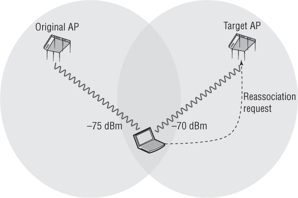
Vendors have different thresholds that kick off the client reassociation process. As mentioned in the earlier example, a 5 dB difference might trigger a client to attempt a forward roam. However, the client might need to hear a 10 dB stronger signal to roam back to the client’s original AP after an initial roam. A higher roaming threshold for a backward roam prevents clients from ping-ponging back and forth between APs.
There is no standard on what triggers a client to initiate the reassociation process. In other words, two client stations could be associated with the same AP and could be receiving the same strength signal, yet one of them may roam before the other because they have different vendor RSSI roaming thresholds. The roaming thresholds in handheld devices tend to encourage roaming more often than the roaming thresholds of WLAN radios found in laptops. Some WLAN vendors attempt to encourage or discourage roaming by manipulating the client station with the use of management frames. However, it should be understood that ultimately the roaming decision is made by the client station. The bottom line is that clients make the roaming decision, and all client roaming thresholds are proprietary.
AP-to-AP Handoff
The 802.11-2012 standard also does not define AP-to-AP handoff communications. As a station roams, the original access point and the target access point should communicate with each other across the distribution system medium (DSM) and help provide a clean transition between the two APs. The DSM is also simply referred to as the distribution system (DS). The DS is typically an 802.3 wired network. The AP-to-AP handoff communications involves two primary tasks:
The target AP informs the original AP that the client station is roaming.
The target AP requests the client’s buffered packets from the original AP.
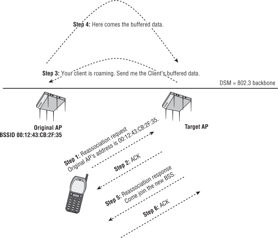
Let’s discuss how basic roaming mechanisms work. As shown in Figure 7.2, roaming occurs after the client and the access point have exchanged reassociation frames, as described in the following steps:
In the first step, the client station sends a reassociation request frame to the target access point. The reassociation request frame includes the BSSID (MAC address) of the access point radio to which the client is currently connected (we will refer to this as the original AP).
The target access point then replies to the station with an ACK.
The target AP attempts to communicate with the original AP by using the distribution system medium (DSM). The DSM is normally an 802.3 Ethernet network. The target AP attempts to notify the original AP about the roaming client to inform the original AP that the client is leaving the original BSS. The target AP also requests that the original AP forward any buffered data. Please remember that these communications between the APs via the DSM are not defined by the 802.11-2012 standard and are proprietary. In a controller-based WLAN solution, the inter-AP communications might instead occur within the controller. Distributed APs that do not require a controller will communicate with each other at the edge of the network.
If this communication is successful, the original access point will use the DSM to forward any buffered data to the target access point.
The target access point then sends a reassociation response frame to the client via the wireless network.
The client sends an ACK to the target access point. The client has now joined the BSS of the target AP.
If the reassociation is not successful, the client will retain its connection to the original AP and either will continue to communicate with the original AP or attempt to roam to another access point.
As the client station roams, the original AP and the new AP should communicate with each other across the DSM and help provide a clean transition between the two. Many manufacturers provide this handoff, but it is not officially part of the 802.11 standard, so each vendor does it using its own proprietary method. In WLAN controller–based solutions, the roaming handoff mechanisms usually occur within the WLAN controller. In controller-less environments, the roaming handoff mechanisms occur at the edge of the network where the conversation is directly between the cooperative APs that do not require a WLAN controller.
Now that you have learned the basics of roaming, we will now begin to discuss the relationship between roaming and security. In the remaining sections of this chapter, we will examine the creation and forwarding of dynamic encryption keys between multiple access points and roaming clients.
RSNA
Let’s review a few things you already learned in Chapter 5, “802.11 Dynamic Encryption Key Generation.” The 802.11i amendment, which was ratified and published as IEEE Std. 802.11i-2004, defined stronger encryption and better authentication methods. The 802.11i security amendment is now part of the 802.11-2012 standard. The 802.11-2012 standard defines what is known as a robust security network (RSN) and robust security network associations (RSNAs).
Keep in mind that a robust security network association (RSNA) requires two 802.11 stations (STAs) to establish procedures to authenticate and associate with each other as well as create dynamic encryption keys through the 4-Way Handshake process. This security association between two stations is referred to as an RSNA. In other words, any two radios must share dynamic encryption keys that are unique between those two radios. CCMP/AES encryption is the mandated encryption method, whereas TKIP/ARC4 is an optional encryption method. Note that the term STA is usually used to refer to a wireless client, but officially it refers to any addressable wireless device. Since an AP is also an addressable wireless device, it is also a station. However, an AP is a special type of station that provides access to the distribution system. Therefore, it is simply referred to as an AP. When referring to an RSNA between two 802.11 stations, realize that this connection is between a client STA and an AP STA.
Every time a client roams, unique encryption keys must be generated using a 4-Way Handshake process between the access point and the client STA. As you have already learned, either an 802.1X/EAP or PSK authentication process is needed to produce the pairwise master key (PMK) that seeds the 4-Way Handshake. Therefore, every time a client roams, the client must reauthenticate. An 802.1X/EAP framework requires multiple EAPOL frames to be exchanged between the supplicant and the authentication server (AS). If a client station has to reauthenticate using 802.1X/EAP every time, the roaming process will be secure but the delay will be significant. This delay will disrupt the communications of time-sensitive applications such as voice and video. A typical 802.1X/EAP roaming handoff can take 700 ms, which far exceeds the needed handoff time of 150 ms or less for VoWiFi. Secure roaming handoff times will be even worse if the RADIUS server resides across a WAN link. The 802.11i security amendment is now part of the 802.11-2012 standard and defines two fast secure roaming mechanisms called preauthentication and PMK caching, which will be discussed later in this chapter.
PMKSA
Robust security network associations (RSNAs) can be broken down into several subtypes. A pairwise master key security association (PMKSA) is the result of a successful IEEE 802.1X/EAP authentication exchange between a supplicant and authentication server (AS) or from a preshared key (PSK) authentication. In other words, once the PMK has been created, a bidirectional security association exists between the authenticator and the supplicant. As you learned in Chapter 5, the PMK is the seeding material for the 4-Way Handshake that creates the pairwise transient key (PTK), which is used for encryption and decryption of unicast traffic. Once the 4-Way Handshake creates the final encryption keys, a pairwise transient key security association (PTKSA) exists between the authenticator and the supplicant. In Chapter 5, we discussed in great detail how the 4-Way Handshake process results in a PTKSA. In this chapter, we will focus more on pairwise master key security associations (PMKSAs).
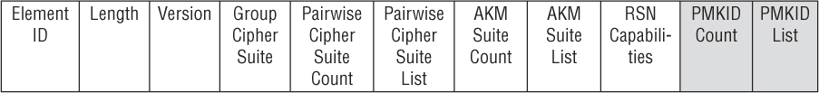
RSN security can be identified by a field found in certain 802.11 management frames. This field is known as the robust security network information element (RSNIE), which is often referred to simply as the RSN information element. An information element is an optional field of variable length that can be found in 802.11 management frames. The RSN information element field is always found in four different 802.11 management frames: beacon management frames, probe response frames, association request frames, and reassociation request frames. The RSN information element can also be found in reassociation response frames if 802.11r capabilities are enabled on an AP and roaming client. In Chapter 5, you learned about the authentication key management (AKM) suites and pairwise cipher suites found in the RSN information element. Figure 7.3 shows the entire format of the RSN information element. Notice the PMKID fields within the RSN information element.
FIGURE 7.3 RSN information element format
A unique identifier is created for each PMKSA that has been established between the authenticator and the supplicant. The pairwise master key identifier (PMKID) is a unique identifier that refers to a PMKSA. The PMKID can reference the following types of pairwise master key security associations:
A PMKSA derived from a PSK for the target AP
A cached PMKSA from an 802.1X/EAP or SAE authentication
A cached PMKSA that has been obtained through preauthentication with the target AP
A PMK-R0 security association derived as part of an FT initial mobility domain association
A PMK-R1 security association derived as part of an FT initial mobility domain association or as part of a fast BSS transition
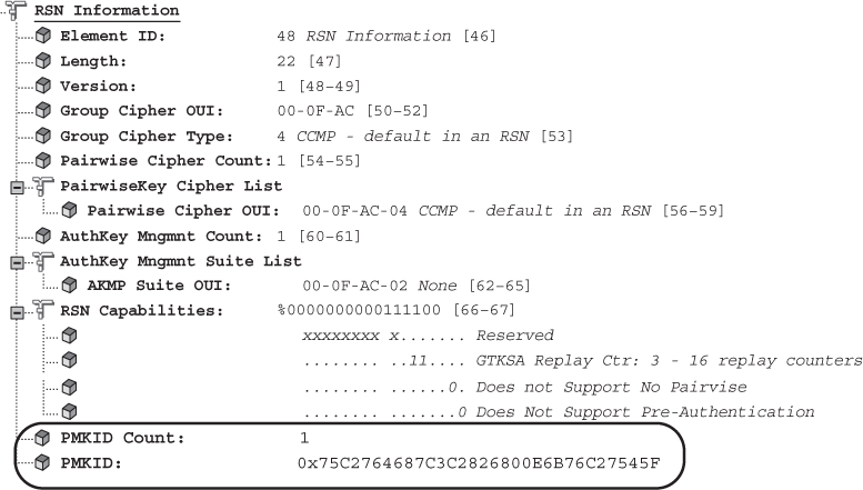
We will discuss PMK caching and preauthentication in the next sections of this chapter. PMK-R0 and PMK-R1 security associations will be discussed in the fast BSS transition (FT) section of this chapter. The pairwise master key identifier (PMKID) is found in the RSN information element in association request frames and reassociation request frames that are sent from a client station to an AP. The PMKID is also found in FT Action frames. Figure 7.4 shows a protocol analyzer capture of a reassociation request frame’s RSN information element and PMKID information. Remember that the PMKID is a unique identifier of an individual PMKSA; however, you will learn that a client station may have established multiple PMKSAs. Therefore, the PMKID Count field specifies the number of PMKIDs in the PMKID List field. The PMKID list contains 0 or more PMKIDs that the STA believes to be valid for a destination AP. The example in Figure 7.4 shows only a single PMKID.
FIGURE 7.4 Pairwise master key identifier (PMKID)
So what exactly comprises a PMKSA? To review, a pairwise master key security association is the result of a successful IEEE 802.1X/EAP authentication exchange between a supplicant and authentication server (AS) or from a preshared key (PSK) authentication. A bidirectional security association exists between the authenticator and the supplicant. The components of a PMKSA include the following:
PMK The pairwise master key that was created.
PMKID The unique identifier of the security association.
Authenticator MAC The MAC address of the authenticator.
Lifetime If the key lifetime is not otherwise specified, then the PMK lifetime is infinite.
AKMP The authentication and key management protocol.
Authorization Parameters Any parameters specified by the authentication server or local configuration. This can include parameters such as the STA’s authorized SSID.
Although WLAN vendors sometimes use the terms PMK and PMKSA interchangeably, they are two separate entities. The PMK is the key that seeds the 4-Way Handshake, whereas the PMKSA consists of all the components just listed, including the PMK. You will see that the most important components of the PMKSA are the PMK, the PMKID, and the authenticator’s MAC address.
The 802.11-2012 standard states that a client station can establish a PMKSA as a result of the following:
Complete 802.1X/EAP authentication
PSK authentication
SAE authentication
PMK cached via some other mechanism
Every time a client station roams to a new access point, a new PMKSA is established. Figure 7.5 depicts the creation of a new PMKSA during reassociation using 802.1X/EAP. PMK #1 is installed on the original AP and the client station. PMK #1 is then used to seed the 4-Way Handshake that is used to create the final keys used for encryption. The client roams to the target AP and reauthenticates with the RADIUS server. The new EAP exchange creates PMK #2, which is installed on the target AP and the client station. PMK #2 is then used to seed the 4-Way Handshake that is used to create the final keys used for encryption in the new BSS.
FIGURE 7.5 802.1X/EAP and PMKSA
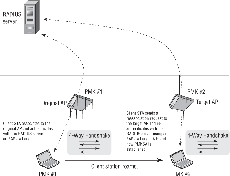
As you can see, each time the client roams to a new target AP, the client station must reauthenticate with the RADIUS server. Although a new PMKSA is established, the time needed to reauthenticate with the RADIUS server is significant. Many applications will not be affected by the roaming handoff time, but the delay will disrupt the communications of time-sensitive applications such as voice and video. Therefore, the 802.11-2012 standard defines three fast secure roaming mechanisms, called PMK caching, preauthentication, and fast BSS transition.
PMK Caching
PMK caching is a method used by APs and client stations to maintain PMKSAs for a period of time while a client station roams to a target AP and establishes a new PMKSA. An authenticator and a client station can cache multiple PMKs. For example, as shown in Figure 7.6, a client station will associate with an original AP and create an original PMK #1. The client will roam to a target AP and create a new PMK #2; however, the original AP and the client station will both cache PMK #1.
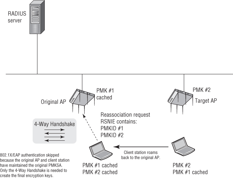
Whenever a client station roams back to the original AP, the client station will send a reassociation request frame that lists multiple PMKIDs in the RSN information element (RSNIE). In other words, the client will be informing the AP about all of the client’s cached PMKs. The 802.11-2012 standard states that “An AP whose authenticator has retained the PMK for one or more of the PMKIDs can skip the IEEE 802.1X/EAP authentication and proceed with the 4-Way Handshake.” In simpler words, when the client roams back to the original AP, both devices still have the original cached PMK #1 and they can skip the 802.1X/EAP exchange. The client does not need to reauthenticate and create a new PMK because the original PMK still exists. The cached original PMK is then used to seed the 4-Way Handshake.
When a client roams to an AP and the 4-Way Handshake is all that is needed, the roaming handoff is usually between 40 and 60 ms, which is fast enough for VoWiFi. Skipping the 802.1X/EAP exchange saves precious time for time-sensitive applications. PMK caching is sometimes called fast secure roam-back because the client station is able to roam back to the original AP and skip the 802.1X/EAP exchange. This is great if a client station roams back to an original AP where it shares a PMKSA, but how does this speed things up when the client station roams forward to a new AP? The short answer is there will not be a cached PMK on the target AP unless there is a method to create or distribute cached PMKs to target APs. Preauthentication is one such method.
Preauthentication
A client station can use preauthentication to establish a new PMKSA with an AP prior to roaming to a new target AP. Preauthentication allows a client station to initiate a new 802.1X/EAP exchange with a RADIUS server while associated with the original AP. The purpose of the new 802.1X/EAP authentication is to create a new PMKSA relationship with a new target AP where the client might roam. As Figure 7.7 shows, the client station sends an EAPOL-Start frame through the original AP over the distribution system (DS). An entire 802.1X/EAP exchange occurs between the client station and the RADIUS server; however, the authenticator is the new target AP. Once the client has preauthenticated, a new PMK #2 is created and cached on both the client station and the target AP. If the client station decides to roam to the target AP, the client does not need to reauthenticate and create a new PMK because a precreated cached PMK already exists. The client station roams to the target AP, and the 4-Way Handshake is all that is needed.
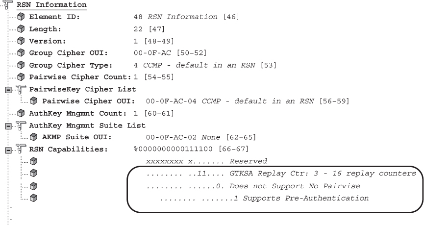
How do client stations know if they can even learn about APs with which they can preauthenticate? Client stations will discover new APs with both active and passive scanning. As shown in Figure 7.8, an AP can indicate to the client station that the AP is capable of preauthentication in the RSN information element sent in the AP’s probe response or beacon frames.
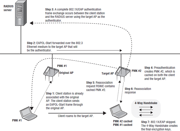
FIGURE 7.8 Preauthentication-enabled AP
Preauthentication was originally intended for use with autonomous APs, although it can be used with WLAN controller systems as well. It should be noted that preauthentication does not scale very well because it requires all APs to create PMKSAs with all clients that might potentially roam to each AP. Every single client station would need to preauthenticate with every single AP in advance. Preauthentication would therefore place a tremendous load on the backend RADIUS server. PMK caching and preauthentication are simply not very scalable solutions, and therefore the 802.11r task group was formed to define more scalable fast secure transition methods between basic service sets. However, most WLAN vendors did not want to wait for the ratification of the 802.11r-2008 amendment, so they implemented a preview of 802.11r mechanisms called opportunistic key caching.
Opportunistic Key Caching (OKC)
Because PMK caching and preauthentication do not scale well, the majority of the WLAN vendors offer a fast secure roaming solution that is an enhancement of PMK caching called opportunistic key caching (OKC). Although it’s widely adopted, please understand that opportunistic key caching is a fast secure roaming (FSR) technique not defined by the 802.11-2012 standard. OKC allows for PMK caching between multiple APs that are under some sort of administrative control.
Unlike preauthentication, OKC does not mandate how a PMK arrives at the target AP. OKC instead allows a client station the opportunity to take advantage of a single cached PMK shared among multiple access points. OKC forwards a PMK from the original AP and then distributes it to other APs. The PMK distribution between APs is dependent on the WLAN architecture and is usually proprietary. In a WLAN controller environment, the PMKs are usually forwarded by the controller to the APs. In a non-controller environment, the PMKs are forwarded by the APs to each other using a proprietary protocol.
To understand OKC, let’s first discuss the formula for a pairwise master key identifier (PMKID). The 802.11-2012 standard defines a PMK identifier as follows:
PMKID = HMAC-SHA1-128(PMK, “PMK Name” || AA || SPA)
The AA is the authenticator’s MAC address, and the SPA is the supplicant’s MAC address. This formula shows that a hash function combines the PMK with the access point and client station MAC addresses to create the PMKID.
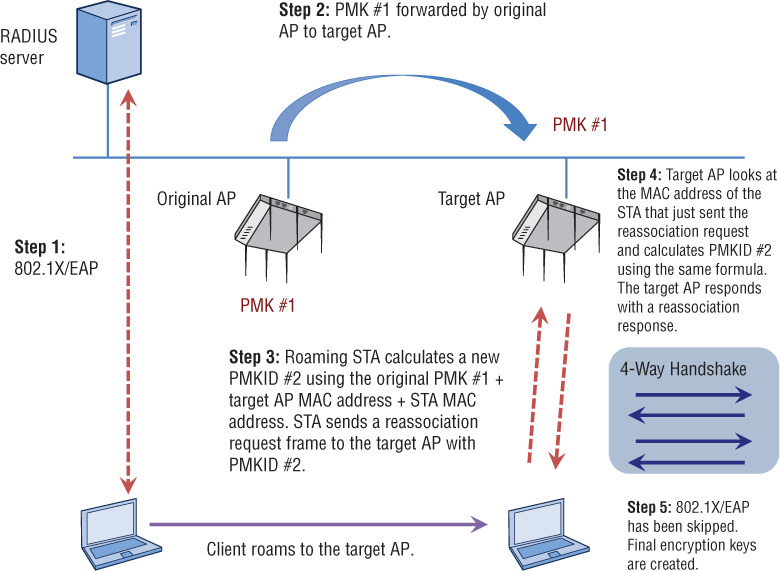
As you can see in Figure 7.9, opportunistic key caching takes advantage of the PMKID formula. In this example, the original AP forwards the original PMK and PMKID to multiple access points at the edge of the network. In a WLAN controller environment, the PMK distribution to APs is usually centralized. Refer to Figure 7.9 when reviewing these steps.
The client station uses full 802.1X/EAP authentication and an original PMK #1 and PMKID #1 are created for use by the original AP and the client station. The original AP and the client station perform a 4-Way Handshake.
The original AP caches PMK #1 and then forwards PMK #1 to the target access point.
The client station calculates a new PMKID #2 using the original PMK #1 + the target AP MAC address + the client MAC. The client sends a reassociation request frame to the target AP with PMKID #2 in the RSN information element.
The target AP looks at the MAC address of the client station that just sent the reassociation request and calculates PMKID #2 using the same formula. The target AP sends a reassociation response frame.
Because the PMKID #2 found in the reassociation request frame matches the PMKID #2 calculated by the target AP, reauthentication is not needed. The AP and the client station are still using the original PMK to seed the 4-Way Handshake, but they are both in possession of the newly calculated PMKID #2, which will allow for a unique security association between the two devices. After the AP sends a reassociation response frame, the 4-Way Handshake is then used to create the final encryption keys shared between the target AP and the client station. 802.1X/EAP authentication was skipped and therefore a fast roaming handoff time has occurred.
FIGURE 7.9 Opportunistic PMK caching
OKC effectively eliminates the need for client preauthentication, and therefore a more scalable solution is provided. OKC offers several advantages over preauthentication. OKC only requires one initial 802.1X/EAP exchange between the client and the authentication server. Therefore, OKC reduces the load that is placed on the RADIUS server. Because only a single 802.1X/EAP exchange occurs, only one original PMK is created. The OKC process uses the client station’s original PMK as seeding material for all the APs. How the cached PMK is distributed between the APs is up to the WLAN vendor. PMK key distribution can occur at the edge between cooperative APs or can be centrally distributed via a WLAN controller. This entire key management process becomes more complex if a client station was to roam to a controller-based AP that tunnels traffic back to a different WLAN controller. Therefore, intercontroller handoff protocols are also entirely proprietary. Some WLAN controller vendors may not support OKC between controllers. In that case, the client station would initiate an 802.1X/EAP exchange and the whole process would start over. OKC will fail if the target AP does not have a newly calculated PMKID that matches the client station’s newly calculated PMKID that is sent in a reassociation request frame. In that case, the client station would initiate an 802.1X/EAP exchange and the whole process would start over.
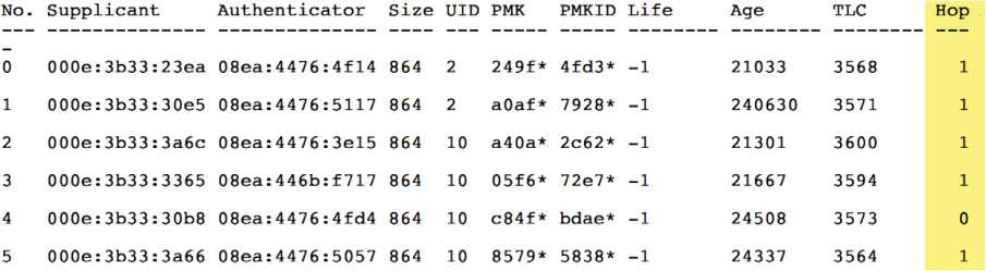
Figure 7.10 displays the roaming cache of a single AP with six different PMKs. Supplicant #4 is a client that is currently associated to the AP. The other supplicants are client stations that are one hop away and not associated to the AP. However, the PMKs of the other stations have already been forwarded to this AP and are cached. Any client that also supports OKC can use its original PMK when roaming to a new AP, as depicted in Figure 7.9.
![]() Real World Scenario
Real World Scenario
There is no defined standard for opportunistic key caching. OKC was originally developed as a short-term fast secure roaming solution by one WLAN vendor until the 802.11r-2008 amendment was ratified and widely supported. The majority of WLAN infrastructure vendors that manufacture APs also quickly adopted OKC. WLAN clients must also support OKC for the process to work. OKC quickly became a de facto standard for fast secure roaming because adoption of 802.11r mechanisms has been extremely slow. Although OKC is supported by all the enterprise-grade AP manufacturers, many WLAN clients do not support OKC because it is not an official roaming standard. For example, OKC is supported for Apple devices that use Mac OS but not supported for iOS devices. Most of the major VoWiFi phone manufacturers also support OKC. Although OKC is natively supported in some client device operating systems, a vast number of WLAN clients simply do not support the technology.
The 802.11r-2008 amendment clearly defined fast secure roaming mechanisms and is now part of the 802.11-2012 standard. The Wi-Fi Alliance has adopted the Voice Enterprise certification that mandates 802.11r. The majority of WLAN infrastructure vendors have finally begun to support 802.11r-2008 mechanisms; however, client-side support for 802.11r is scarce.
Proprietary FSR
WLAN vendor Cisco Systems has long offered a proprietary version of fast secure roaming called Cisco Centralized Key Management (CCKM). Cisco demonstrated market leadership with CCKM; however, CCKM only works within a Cisco WLAN infrastructure. Now that FSR solutions are becoming standardized, CCKM will likely take a backseat much like the ISL Ethernet switch protocol did with the introduction of IEEE Std. 802.1Q.
CCKM falls within Cisco’s licensed CCX program that other vendors may license. The current implementation of CCKM requires Cisco-compatible hardware and works with EAP-LEAP, EAP-FAST, PEAPv1 (EAP-GTC), PEAPv0 (EAP-MSCHAPv2), and EAP-TLS. CCKM uses a Cisco access point or controller to cache security credentials and effectively takes the place of the RADIUS server when the client stations authenticate. Like all FSR solutions, CCKM shortens the roaming handoff delay.
NOTE
You will not be tested on CCKM or any other vendor proprietary technologies mentioned in this book. The CWSP exam is a vendor-neutral exam.
Fast BSS Transition (FT)
The 802.11r-2008 amendment is known as the fast basic service set transition (FT) amendment. Think of the term fast BSS transition as the technical name for standardized fast secure roaming. The main difference between OKC and FT is that the 802.11r-2008 amendment fully defined the key hierarchy used when creating cached keys. The fast BSS transition mechanisms originally defined in the 802.11r-2008 amendment are now found in clause 12 of the 802.11-2012 standard.
As we have previously stated, OKC key management is a preview of FT, which is also designed for a method of pairwise master key (PMK) distribution. FT mechanisms operate within a mobility domain. A mobility domain is a set of basic service sets (BSSs), within the same extended service set (ESS), that supports fast BSS transitions. In simpler words, a mobility domain is a group of APs that belong to the same ESS where client stations can roam in a fast and secure manner. The first time a client station enters a mobility domain, the client will associate with an AP and perform an initial 802.1X/EAP authentication. From that point forward, as the client station roams between APs, the client will be using fast BSS transitions. You will learn later in this chapter that a fast BSS transition can be over-the-air or over-the-DS.
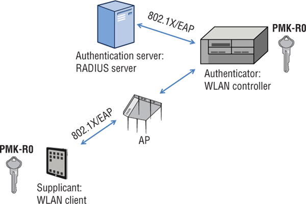
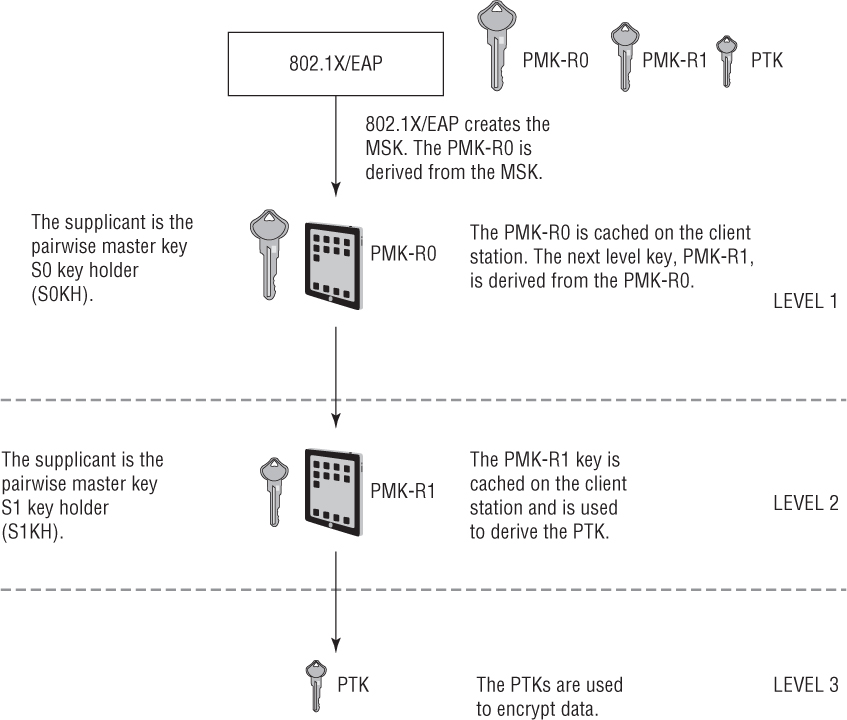
As you learned in Chapter 4, “802.1X/EAP Authentication,” an 802.1X/EAP exchange creates a master session key (MSK) that is used to create a pairwise master key (PMK) for non-FT roaming. FT also uses the 802.1X/EAP exchange to create the master session key, which seeds a multi-tiered key management solution. As shown in Figure 7.11, after the supplicant and the RADIUS server exchange credentials, a first-level pairwise master key called the PMK-R0 is created from the master session key and sent to the authenticator and the WLAN client. Depending on the WLAN architecture, the 802.1X/EAP authenticator can either be an AP or a WLAN controller.
FIGURE 7.11 802.1X/EAP and first-level pairwise master key (PMK-RO)
FT mechanisms introduce multiple layers of PMKs that are cached in different devices. Fast BSS transition uses a three-level key hierarchy:
Pairwise Master Key R0 (PMK-R0) The first-level key of the FT key hierarchy. This key is derived from the master session key (MSK).
Pairwise Master Key R1 (PMK-R1) The second-level key of the FT key hierarchy.
Pairwise Transient Key (PTK) The third-level key of the FT key hierarchy. The PTK is the final key used to encrypt 802.11 data frames.
Fast BSS transition also assigns different roles to different devices. As shown in Table 7.1, each device is assigned a key holder role to manage one or more of the multiple keys used in the FT key hierarchy.
Device |
Key holder role |
Original AP or WLAN controller |
Pairwise master key (PMK) R0 key holder (R0KH) |
Access point |
Pairwise master key (PMK) R1 key holder (R1KH) |
Client station |
Pairwise master key (PMK) S0 key holder (S0KH) |
Client station |
Pairwise master key (PMK) S1 key holder (S1KH) |
The various levels of FT keys are derived and stored in different WLAN devices depending on the WLAN architecture that has been deployed. For example, in a controller-less environment, the first level PMK-R0 key is created and cached on an access point. In an environment where WLAN controllers are deployed, the first level PMK-R0 key is created and cached on a WLAN controller.
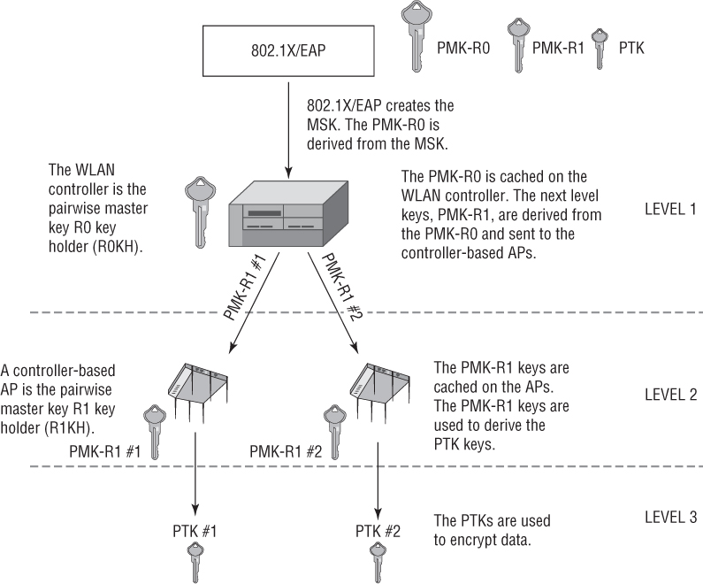
802.1X/EAP creates the master session key (MSK). The MSK is used to create the first-level master key, called a PMK-R0. In the example in Figure 7.12, the PMK-R0 is created and cached on the WLAN controller. The WLAN controller is the key holder for the first-level key. The second-level PMK-R1 keys are derived from the PMK-R0 and sent from the WLAN controller to the controller-based APs. The PMK-R1 keys are cached on the APs. The access points are the key holders for the PMK-R1 keys. The PMK-R1 keys are used to derive the PTKs, which are used to encrypt 802.11 data frames.
FIGURE 7.12 FT Key hierarchy—WLAN controller infrastructure
As shown in Figure 7.13, the various levels of FT keys are also derived and stored on the client station. 802.1X/EAP creates the master session key (MSK). The MSK is used to create the first-level master key, called a PMK-R0. The PMK-R0 is cached on the supplicant, which is the client station. The client station is the key holder for the first-level key. The PMK-R0 is cached on the client station. The client station derives the second-level key, PMK-R1, from the PMK-R0. The PMK-R1 key is cached on the client station. The supplicants are the key holders for the PMK-R1 keys. The PMK-R1 keys are used to derive the PTKs, which are used to encrypt unicast 802.11 data frames.
To summarize, the order of the keys is as follows:
MSK ![]() PMK-R0
PMK-R0 ![]() PMK-R1
PMK-R1 ![]() PTK
PTK
Fast BSS transition requires that keys sent between WLAN devices be distributed over a secure channel but does not define the actual secure method of distribution. For example, the 802.11r-2008 amendment did not specify how the PMK-R1 keys are sent from the WLAN controller to the controller-based APs. If multiple WLAN controllers are used, this becomes even more complex. There is no real definition of how keys should be exchanged between controllers; therefore, intercontroller handoff protocols are entirely proprietary. This also means that it remains highly doubtful that distribution of these keys between WLAN infrastructure devices from different WLAN vendors will be effective.
FIGURE 7.13 FT key hierarchy—supplicant
Most WLAN controller vendors encrypt/decrypt client traffic at the edge of the network using the access points. However, some WLAN vendors perform encryption at the controller level instead of at the AP level. End-to-end encryption provides data privacy between the client at the access layer and the WLAN controller that is typically deployed at the core. In that scenario, the WLAN controller functions as both the pairwise master key R0 holder (R0KH) and the pairwise master key R1 holder (R1KH).
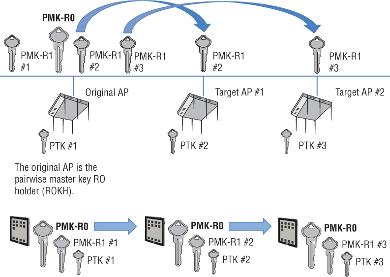
Now let us take a look at FT key hierarchy in a distributed AP architecture that does not require a WLAN controller. The 802.1X/EAP exchange creates the master session key (MSK). The MSK is used to create the first-level master key, called a PMK-R0. In the example in Figure 7.14, the PMK-R0 is created and cached on an AP where the client first associates. The original AP is the key holder for the first-level key. The second-level PMK-R1 keys are derived from the PMK-R0 and sent from the original AP to other target APs over a secure channel. As previously stated, how the PMK-R1 keys are securely distributed is outside of the scope of the 802.11-2012 standard. The PMK-R1 keys are cached on the target APs, which are the key holders for the PMK-R1 keys. The PMK-R1 keys are used to derive the PTKs, which are used to encrypt unicast 802.11 data frames.
In Figure 7.14, the PMK-R0 is cached on the supplicant, which is the client station. The client station is the key holder for the first-level key. The PMK-R0 remains cached on the client station as the client roams between access points. From the PMK-R0, the client station derives the second-level PMK-R1 keys for each target AP. The PMK-R1 keys are also cached on the client station, which functions as the key holder for all the PMK-R1 keys. The unique PMK-R1 keys are used to derive unique PTKs, which are used to encrypt unicast 802.11 data frames.
FIGURE 7.14 FT Key hierarchy—distributed AP infrastructure
Information Elements
To achieve successful fast secure roaming, FT mechanisms still require the use of the RSN information element to indicate the specific authentication key management (AKM) suites and pairwise cipher suites that are being used between the AP and the client station. The 802.11-r-2008 amendment defined four new information elements. However, we are going to focus on just two of them.
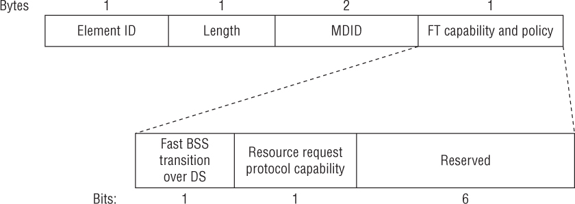
The mobility domain information element (MDIE) is used to indicate the existence of a mobility domain as well as the method of fast BSS transition. As shown in Figure 7.15, the mobility domain identifier (MDID) field is the unique identifier of the group of APs that constitute a mobility domain. The FT capability and policy field is used to indicate whether over-the-air or over-the-DS fast BSS transition is to be performed. We will discuss the difference between over-the-air and over-the-DS fast BSS transition later in this chapter.
FIGURE 7.15 Mobility domain information element
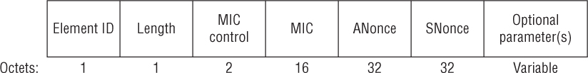
The fast BSS transition information element (FTIE) includes information needed to perform the FT authentication sequence during a fast BSS transition. As shown in Figure 7.16, some of the fields look very similar to the information used during a typical 4-Way Handshake exchange. In the next section, you will see how this information is used in a similar manner during the various FT processes.
FIGURE 7.16 Fast BSS transition information element
FT Initial Mobility Domain Association
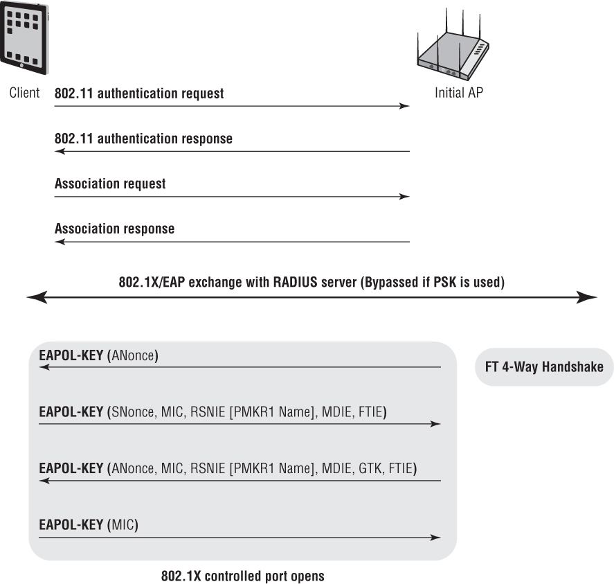
The FT initial mobility domain association is the first association in the mobility domain. As shown in Figure 7.17, the client station first exchanges the standard 802.11 Open System authentication request/response frames with the first AP. The client station and AP then use the MDIE and FTIE information in the association request/response frames to indicate future use of the FT procedures. An original 802.1X/EAP exchange between the client station and the RADIUS server must then occur so seeding material is established for a FT 4-Way Handshake that occurs only during the first association. The PTK and GTK encryption keys are created during the FT 4-Way Handshake and the 802.1X/EAP controlled port is unblocked. The original 802.1X/EAP exchange also creates the master session key (MSK) that is used for the FT key hierarchy. As you can see, the FT initial mobility domain association is not much different than any initial association used by clients that do not support fast BSS transition. The main difference is that extra information, such as the MDIE and FTIE, is communicated during an FT initial mobility domain association.
FIGURE 7.17 FT initial mobility domain association
FT Initial Mobility Domain Association
In this exercise, you will use a protocol analyzer to view the 802.11 frame exchanges used by a client and AP for an FT initial mobility domain association.
To perform this exercise, you need to first download the following file from the book’s online resource area, which can be accessed at www.sybex.com/go/cwsp2e.
FT.PCAP
After the capture file has been downloaded, you will need packet analysis software to open the file. If you do not already have a packet analyzer installed on your computer, you can download Wireshark from www.wireshark.org.
Using the packet analyzer, open the FT.PCAP file. Most packet analyzers display a list of capture frames in the upper section of the screen, with each frame numbered sequentially in the first column.
Click packet 4, which is a beacon frame transmitted by an AP. Typically in the lower section of the screen is the packet details window. This section contains annotated details about the selected frame. In this window, locate and expand the beacon frame. In the body of the beacon frame, expand the tagged parameters and locate the mobility domain information element (MDIE). The access point uses the AP to inform FT-capable clients of the mobility domain identifier (MDID).
Click packet 11, which is an association request from an Apple iOS device. In the body of the frame, expand the tagged parameters and locate the mobility domain information element (MDIE). The client is informing the AP that the client is capable of fast BSS transition.
Observe the 802.1X/EAP exchange in packets 15 through 52. After 802.1X/EAP is completed, the first-level PMK-RO key is created on the AP and the client. A second-level PMK-R1 key is derived from the PMK-R0-key.
Observe the FT 4-Way Handshake between the client and the AP in packets 53 through 60. Click packet 55 and locate the FT information element. Observe the PMK-R0 and PMK-R1 information. After the FT 4-Way Handshake is complete, the client and AP will use the newly created PTK to encrypt and decrypt unicast 802.11 data frames between the two radios. The PMK-RO can then be used to create more PMK-R1 keys for the target APs to which the client may potentially roam.
After the initial association, two new methods are defined for a client station to roam from the original AP to a target AP. We will now discuss these two methods of fast BSS transition.
Over-the-Air Fast BSS Transition
Let’s consider all the frames that need to be exchanged between a client station and an AP. First, a client has to exchange Open System authentication frames and association frames, as was shown in Figure 7.17. This is a total of four frames, not including the ACKs. Next, a successful 802.1X/EAP exchange between the supplicant and the RADIUS server is needed. The 802.1X/EAP exchange requires multiple frames. Finally, a 4-Way Handshake exchange is needed between the AP and the client station to create the final dynamic encryption keys. We already know that the purpose of FT and other fast secure roaming mechanisms is to eliminate the need for a new 802.1X/EAP frame exchange every time a client roams. However, the initial four frames of Open System authentication and reassociation are still needed as well as the four frames used during the 4-Way Handshake.
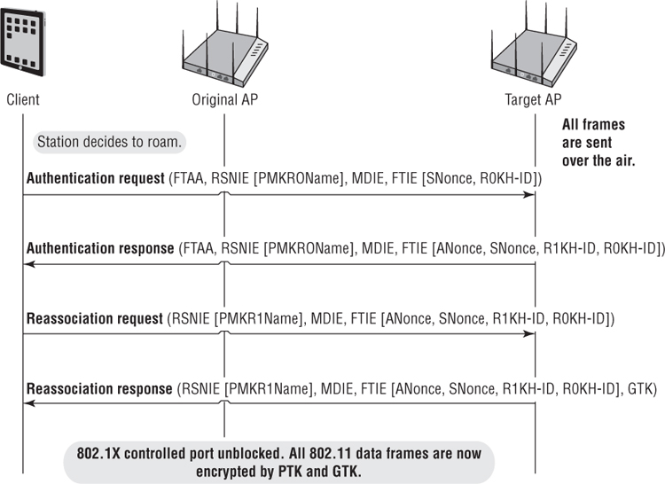
The FT process defines a more efficient method that effectively combines the initial Open System authentication and reassociation frames with the 4-Way Handshake frames. In other words, four fewer frames are needed when a client roams, thus speeding up the roaming process. As shown in Figure 7.18, an FT protocol frame exchange is used to initiate the roaming exchange and create dynamic encryption keys. Note that the authentication request/response frames and reassociation request/response frames carry an FT authentication algorithm (FTAA) along with nonces and other information needed to create the final dynamic keys. The process shown in Figure 7.18 is known as over-the-air fast BSS transition. The client station communicates directly with the target AP using standard 802.11 authentication with the FT authentication algorithm. The PMK-R1 key is the seeding material for the over-the-air fast BSS transition process that creates the final pairwise transient key (PTK).
FIGURE 7.18 Over-the-air fast BSS transition
Over-the-DS Fast BSS Transition
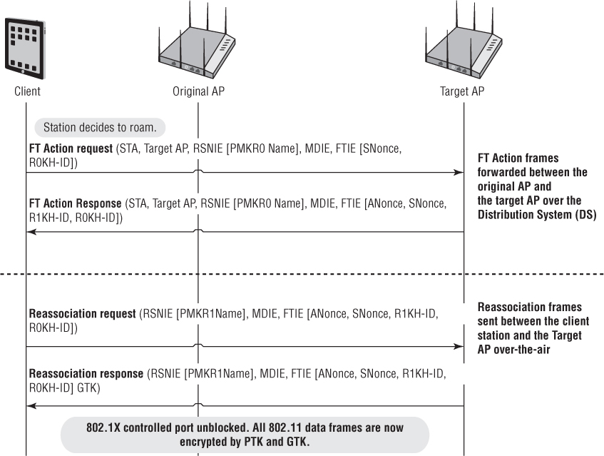
An alternative to the FT method is over-the-DS fast BSS transition, which requires the use of FT Action frames to complete the PTK creation process. The over-the-DS process uses the FT Action frames over the wired 802.3 infrastructure. As shown in Figure 7.19, the client station sends an FT Action request frame to the original AP. The FT Action request frame is forwarded over the distribution system (DS), which is the wired infrastructure. The target AP responds back to the client station over the DS with an FT Action response frame. The reassociation request and response frames are then sent from the client station to the target AP over the air. The PMK-R1 key is the seeding material for the over-the-DS fast BSS transition exchange that creates the final pairwise transient key (PTK). Over-the-DS fast BSS transition is considered to be an optional method that may be supported by a few WLAN vendors.
FIGURE 7.19 Over-the-DS fast BSS transition
Over-the-Air Fast BSS Transition
In this exercise, you will use a protocol analyzer to view the 802.11 frame exchanges used by a client to roam to a target AP using over-the-air fast BSS transition.
To perform this exercise, you need to first download the following file from the book’s online resource area, which can be accessed at www.sybex.com/go/cwsp2e.
FT.PCAP
After the capture file has been downloaded, you will need packet analysis software to open the file. If you do not already have a packet analyzer installed on your computer, you can download Wireshark from www.wireshark.org.
Using the packet analyzer, open the FT.PCAP file. Most packet analyzers display a list of capture frames in the upper section of the screen, with each frame numbered sequentially in the first column.
The over-the-air fast BSS transition in frame exchange occurs between packets 95 and 102. Click packet 95, which is an authentication request frame from the client to a target AP. In the body of the frame, expand the tagged parameters and locate the FT information element. Notice that the FT key exchange has begun.
To observe the second frame used for the FT key exchange, click packet 97, which is an authentication response frame from the target AP to the client. In the body of the frame, expand the tagged parameters and locate the FT information element.
Click packet 99, which is the reassociation request frame sent from the client to the target AP. In the body of the frame, expand the fixed parameters. Notice that the client is currently associated to the original AP with the BSSID MAC address of 08:ea:44:76:b5:68. Expand the tagged parameters and locate the FT information element. Notice that the FT key exchange continues.
Click packet 101, which is the reassociation response frame sent from the target AP to the roaming client. In the body of the frame, expand the fixed parameters. Notice the successful status code and the association ID. Expand the tagged parameters and locate the FT information element. Notice that the FT key exchange completes. The client has completed over-the-air fast BSS transition and has roamed to the target AP with the BSSID address of 08:ea:44:78:14:28. When the client roamed, an 802.1X/EAP exchange was not necessary. The 4-Way Handshake was also not necessary because the dynamic keys were created using the authentication and reassociation frames.
Observe the encrypted data frame exchange between the client and the new AP in packets 113 through 116. These unicast data frames are encrypted with the unique PTK that was generated as a result over the over-the-air fast BSS transition.
As previously mentioned, due to the multiple 802.1X/EAP frame exchanges between a RADIUS server and WLAN supplicant, roaming handoffs take way too much time. As you have learned, fast secure roaming mechanisms such as OKC or FT address this problem. So far we have discussed fast BSS transition as a solution when 802.1X/EAP is deployed. If an AP and a client both support FT, a client does not have to reauthenticate with the RADIUS server when the client roams. Furthermore, the 4-Way Handshake frames are not needed because the dynamic encryption keys are constructed in the frames used in over-the-air fast BSS transition. FT roaming is a much faster roaming handoff that should typically be less than 50 ms.
When PSK authentication is deployed, roaming handoffs are always fast because an 802.1X/EAP frame exchange is never needed. When a PSK client roams to a PSK access point, the frames exchanges consist of reassociation request/response and the 4-Way Handshake to create new keys. Typically roaming handoffs with standard PSK authentication take 40–60 ms. You should also understand that when PSK authentication is deployed, FT roaming mechanisms also occur if the clients and APs all support FT. Roaming handoff times can be shortened even more when FT is deployed. When using PSK authentication, the FT initial mobility domain association to the first AP consists of the same frames used in Figure 7.17 minus the 802.1X/EAP exchange. When an FT client roams using over-the-air fast BSS transition, the 4-Way Handshake is not needed because the encryption keys are created in the FT Action frames and reassociation request/response frames. By eliminating the 4-Way Handshake, an FT roam, when using PSK authentication, is slightly faster.
In Chapter 6, “PSK Authentication,” you learned about a future replacement for PSK authentication called Simultaneous Authentication of Equals (SAE). The 802.11-2012 standard also supports fast BSS transition for SAE. Therefore, the RSN information element found in WLAN management frames supports three authentication and key management (AKM) suites:
FT authentication using IEEE 802.1X, with FT key management
FT authentication using PSK, with FT key management
FT authentication over SAE with SHA-256, with FT key management
![]() Real World Scenario
Real World Scenario
In most cases, new 802.11 technology allows for backward compatibility. When enterprise APs are deployed with the new 802.11 technology, legacy client devices will still require connectivity. For example, client devices that do not support fast BSS transition should still be able to associate to an SSID that has been configured for FT. As a matter of fact, AP configured for FT should be able to support clients that support FT and clients that support OKC on the same SSID. Clients that support neither fast roaming mechanism should also be able to associate. However, in the real world you might run into problems. When FT is configured on an access point, the AP will broadcast management frames with new information elements. For example, the mobility domain information element (MDIE) will be in all beacon and probe response frames. Unfortunately, the drivers of some older legacy client radios may not be able to process the new information in these management frames. The result is that legacy clients may have connectivity problems when an AP is configured for FT. Whenever any new 802.11 technology requires new information elements in the 802.11 management frames, there may be a possible connectivity problem with older legacy radios. Always test the legacy client population when configuring APs for fast BSS transition. If connectivity problems arise, consider using a separate SSID solely for fast BSS transition devices. However, please remember that every SSID consumes more airtime due to the Layer 2 management overhead. Additionally, as more devices begin to support FT, upgrade your client devices.
802.11k
The 802.11k-2008 amendment in conjunction with the recently ratified 802.11r-2008 amendment have the potential to improve roaming performance within secure 802.11 WLANs. 802.11k defines radio resource measurement (RRM) mechanisms that enable 802.11k-compliant radios to better understand the RF environment in which they exist. If an 802.11 radio is not transmitting, it can evaluate the RF environment and radio link performance while the radio is listening. Radio resource measurements can be made by an AP or a client station. The measurements can be taken locally and can be requested and obtained from another station. RRM data can be made available to upper protocol layers, where it can be used for a range of applications, such as Voice over Internet Protocol (VoIP).
Measurements such as the channel load request/report and the neighbor request/report may be used to collect pre-handoff information, which can drastically speed up handoffs between access points. The whole purpose behind RRM is that client stations and/or APs can make intelligent decisions about the most effective way to utilize the available spectrum, power, and bandwidth for desired WLAN communications.
One key component of RRM is the neighbor report, which is used by client stations to gain information from the associated AP about potential roaming neighbors. As defined by the 802.11k-2008 amendment, the neighbor report information assists the fast roaming process by providing a method for the client to request the associated AP to measure and report about neighboring APs available within the same mobility domain. This can speed up the client scanning process by informing the client device of nearby APs to which it may roam. The neighbor report information is typically delivered through a request/report frame exchange inside 802.11 Action frames. In the neighbor report, the client learns about multiple fields of operational information about each potential AP roaming target, including
BSSID of the neighbor AP
Mobility domain
Whether the neighbor AP supports the same security as the current AP
Quality of service (QoS)
Automatic Power Save Delivery (APSD)
Radio measurement
BlockAck method
Spectrum management
Regulatory class
Channel number
PHY type (802.11a/b/g/n/ac)
As you learned earlier in this chapter, clients make the roaming decision as opposed to the APs or WLAN controllers. Clients will still look to roam to APs using active and passive scanning, and they will still evaluate locally the RF environment based on RSSI metrics. Client stations will still make the roaming decision; however, the neighbor reports will provide the client stations with additional input so the client stations can make better roaming decisions.
In addition to the neighbor report, a multitude of radio measurements from client devices can provide information to APs to generate and update the neighbor report. They include the following:
Transmit Power Control (TPC) information enables the client device to calculate the link budget prior to association.
Power capability elements allow the client device to compute range data as part of the monitoring of neighboring APs during an active call.
QoS metrics provide troubleshooting data.
Client device statistic measurements include voice diagnostics and management for QoS.
Power constraint element (2.4 GHz and 5 GHz) provides information that reduces co-channel interference.
Quiet-time announcement (2.4 GHz and 5 GHz) permits the collection of measurements for diagnostics and troubleshooting.
The 802.11k amendment is now part of the 802.11-2012 standard. It was originally ratified in June 2008 and was published as IEEE 802.11k-2008. It should be noted that 802.11k mechanisms will only work if supported by both AP and the clients. Most enterprise WLAN vendor APs support 802.11k and RRM mechanisms. Client-side support for 802.11k is still sparse but growing. For example, newer Apple iOS mobile devices support 802.11k mechanisms.
![]() Real World Scenario
Real World Scenario
Client devices that do not support 802.11k RRM mechanisms should still be able to associate to an SSID that has been configured for 802.11k. However, in the real world you might run into problems. When 802.11k is configured on an access point, the AP will broadcast management frames with multiple 802.11k information elements. For example, the RRM Information Capabilities information element will be in all beacon and probe response frames. Unfortunately, the drivers of some older legacy client radios may not be able to process the new information in these management frames. The result is that legacy clients may have connectivity problems when an AP is configured for 802.11k. Whenever any new 802.11 technology requires new information elements in the 802.11 management frames, there may be a possible connectivity problem with older legacy radios. Always test the legacy client population when configuring APs for 802.11k. Client devices that support 802.11k will usually also support 802.11r mechanisms. If connectivity problems arise, consider using a separate SSID solely for 802.11k and 802.11r clients. However, please remember that every SSID consumes more airtime due to the Layer 2 management overhead. Additionally, as more devices begin to support 802.11k, upgrade your client devices.
Radio Resource Management and Neighbor Reports
In this exercise, you will use a protocol analyzer to view the 802.11 frame exchanges used by a client and AP for an FT initial mobility domain association.
To perform this exercise, you need to first download the following file from the book’s online resource area, which can be accessed at www.sybex.com/go/cwsp2e.
FT.PCAP
After the capture file has been downloaded, you will need packet analysis software to open the file. If you do not already have a packet analyzer installed on your computer, you can download Wireshark from www.wireshark.org.
Using the packet analyzer, open the FT.PCAP file. Most packet analyzers display a list of capture frames in the upper section of the screen, with each frame numbered sequentially in the first column.
Click packet 103, which is an 802.11 Action frame transmitted by an Apple iOS client device. Typically in the lower section of the screen is the packet details window. This section contains annotated details about the selected frame. In this window, locate and expand the Action frame. In the body of the Action frame, expand the tagged parameters and notice that this Action frame is being used as a neighbour report request. The client is asking the AP if the AP has information about any neighboring APs.
Click packet 105 which is an 802.11 Action frame transmitted by the AP. In the body of the Action frame, expand the fixed parameters and notice that this Action frame is being used as a neighbor report response. In the body of the Action frame, expand the tagged parameters and view the neighbor report about the AP with a BSSID of 08:ea:44:76:b5:68, which is transmitting on channel 48.
802.11v
The IEEE 802.11v-2011 amendment defined wireless network management (WNM) as information about network resources that is exchanged between the client devices and an AP. The intended goal is to enhance overall performance of the wireless network. Whereas 802.11k provides exchange of information about the RF environment, 802.11v exchanges WNM information about surrounding existing network conditions. There are many categories of WNM information that can be potentially exchanged between clients and APs, including
BSS Max Idle Period Management
BSS Transition Management
Channel Usage
Collocated Interference Reporting
Diagnostic Reporting
Directed Multicast Service (DMS)
Flexible Multicast Service (FMS)
Multicast Diagnostic Reporting
Event Reporting
Location Services
Multiple BSSID Capability
Proxy ARP
QoS Traffic Capability
SSID List
Triggered STA Statistics
TIM Broadcast
Timing Measurement
Traffic Filtering Service
U-APSD Coexistence
WNM-Notification
WNM-Sleep Mode
802.11v is now part of the 802.11-2012 standard. It was originally ratified in 2011 and was published as IEEE 802.11v-2011. Keep in mind that 802.11v mechanisms will work only if supported by both AP and the clients. Support for WNM mechanisms defined by 802.11v-2011 is currently not widespread, although some of the WNM capabilities are supported in WLAN vendor APs that are Voice Enterprise certified.
Voice Enterprise
In 2012, the Wi-Fi Alliance debuted a vendor-interoperability certification called Voice Enterprise that defines enhanced support for voice applications in the enterprise environment. Many aspects of the 802.11r, 802.11k, and 802.11v amendments are tested for Voice Enterprise certification. Effective enterprise-grade voice over Wi-Fi solutions must address two major requirements:
Voice Quality Voice quality has to be consistently good throughout the call, in all load conditions. To ensure that client devices maintain good voice quality, latency, jitter, and packet loss have to be consistently low.
Data Traffic Coexistence Wi-Fi networks are used for both voice and data applications. Therefore, voice calls must coexist and share network resources with data traffic, which often accounts for the largest portion of the network load.
In order to achieve voice quality and data traffic coexistence, the following general aspects of the Voice Enterprise certification are required:
Prioritization Support for Wi-Fi Multimedia (WMM) QoS mechanisms is mandatory. WMM enables the AP to recognize and prioritize voice traffic over other application traffic, such as Internet browsing, email reading, or large file downloads.
Bandwidth Management APs must support WMM-Admission Control, which optimizes traffic management by admitting only those traffic streams that an AP can support at a given time. WMM-AC also enables load balancing.
Seamless Transitions Across the Wi-Fi Network Support for IEEE 802.11r fast BSS transition, which allows fast AP handoffs (known as BSS transitions) even while using advanced security methods, is also mandatory. 802.11r aspects are mandatory for AP and client devices.
Network Measurement and Management Support for IEEE standards for radio resource measurement (802.11k) and wireless network management (802.11v) is also mandatory. 802.11k aspects are mandatory for AP and client devices. 802.11v mechanisms are optional.
Security WPA2-Enterprise security is mandatory for both APs and clients.
Battery Life APs must support the power save mechanism WMM-Power Save. Support for WMM-PS is optional for clients.
Performance is measured using four (802.11b) or ten (802.11a/g/n/ac) concurrent simulated voice calls, a high-speed video stream, and background data traffic, designed to represent a fully loaded enterprise wireless network environment. Testing is done while fast roaming transitions between APs are executed. Performance is measured under simulated, but realistic, network conditions. Performance of equipment submitted for Wi-Fi Voice-Enterprise certification has to meet the following thresholds to ensure that the Wi-Fi network preserves good voice call quality:
Latency (One way delay < 50 ms)
Jitter (< 50 ms)
Packet Loss (< 1 percent)
Consecutive lost packets (no more than 3)
![]() Real World Scenario
Real World Scenario
Most major WLAN enterprise vendors offer support for Voice Enterprise in their access points. Usually a WLAN administrator will be able to configure all three 802.11k/r/v mechanisms together or independently on an access point that is Voice Enterprise certified. However, client-side support for Voice Enterprise is not widespread. Any client devices that were manufactured before 2012 simply will not support 802.11r/k/v operations. The bulk of newer devices also do not support Voice Enterprise capabilities. However client-side support is growing. For example, Apple iOS devices support 802.11k/r/v: https://support.apple.com/en-us/HT202628. Many Android OS clients also support some Voice Enterprise capabilities. Roaming performance will gradually improve as more client devices support 802.11k/r/v mechanisms.
Layer 3 Roaming
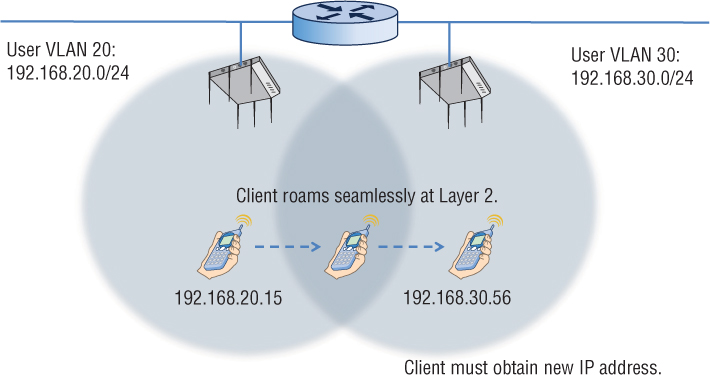
One major consideration when designing a WLAN is what happens when client stations roam across Layer 3 boundaries. Wi-Fi operates at Layer 2 and roaming is essentially a Layer 2 process. As shown in Figure 7.20, the client station is roaming between two access points. The roam is seamless at Layer 2, but user VLANs are tied to different subnets on either side of the router. As a result, the client station will lose Layer 3 connectivity and must acquire a new IP address. Any connection-oriented applications that are running when the client reestablishes Layer 3 connectivity will have to be restarted. For example, a VoIP phone conversation would disconnect in this scenario, and the call would have to be reestablished.
Because 802.11 wireless networks are usually integrated into preexisting wired topologies, crossing Layer 3 boundaries is often a necessity, especially in large deployments. The only way to maintain upper-layer communications when crossing Layer 3 subnets is to provide a Layer 3 roaming solution that is based on the Mobile IP standard. Mobile IP is an Internet Engineering Task Force (IETF) standard protocol that allows mobile device users to move from one Layer 3 network to another while maintaining their original IP address. Mobile IP is defined in IETF Request for Comment (RFC) 5944. Layer 3 roaming solutions based on Mobile IP use some type of tunneling method and IP header encapsulation to allow packets to traverse between separate Layer 3 domains with the goal of maintaining upper-layer communications. Most WLAN vendors now support some form of Layer 3 roaming solution, as shown in Figure 7.21.
FIGURE 7.20 Layer 3 roaming boundaries
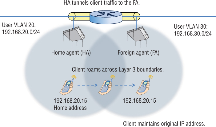
A mobile client receives an IP address also known as a home address on a home network. The mobile client must register its home address with a device called a home agent (HA). As depicted in Figure 7.21, the client’s original associated access point serves as the home agent. The home agent is a single point of contact for a client when it roams across Layer 3 boundaries. The HA shares client MAC/IP database information in a table, called a home agent table (HAT) with another device called the foreign agent (FA).
In this example, the foreign agent is another access point that handles all Mobile IP communications with the home agent on behalf of the client. The foreign agent’s IP address is known as the care-of address. When the client roams across Layer 3 boundaries, the client is roaming to a foreign network where the FA resides. The FA uses the HAT tables to locate the HA of the mobile client station. The FA contacts the HA and sets up a Mobile IP tunnel. Any traffic that is sent to the client’s home address is intercepted by the HA and sent through the Mobile IP tunnel to the FA. The FA then delivers the tunneled traffic to the client and the client is able to maintain connectivity using the original home address. In our example, the Mobile IP tunnel is between two APs on opposite sides of a router. If the user VLANs exist at the edge of the network, tunneling of user traffic occurs between access points that assume the roles of HA and FA. The tunneling is often distributed between multiple APs. However, user VLANs may reside back in a DMZ or at the core layer of the network along with a WLAN controller. In a single WLAN controller environment, the Layer 3 roaming handoffs exist as control plane mechanisms within the single controller. In a multiple WLAN controller environment, an IP tunnel is created between controllers that are deployed in different routed boundaries with different user VLANs. One controller functions as the home agent and another functions as the foreign agent.
Although maintaining upper-layer connectivity is possible with these Layer 3 roaming solutions, increased latency is sometimes an issue. Additionally, Layer 3 roaming may not be a requirement for your network. Less complex infrastructure often uses a simpler flat Layer 2 design. Larger enterprise networks often have multiple user and management VLANs linked to multiple subnets; therefore, a Layer 3 roaming solution will be required.
Troubleshooting
The best way to ensure that seamless roaming will commence is proper design and a thorough site survey. Proper WLAN design normally requires –65 dBm primary coverage and secondary coverage of usually –5 dB lower than the primary coverage cells. The only way to determine whether proper primary and secondary coverage is in place is by conducting a coverage analysis site survey. Proper site survey procedures are discussed in detail in the CWNA: Certified Wireless Network Administrator Official Study Guide, Fourth Edition by David Coleman and David Westcott (Sybex, 2014).
Changes in the WLAN environment can also cause roaming headaches. RF interference will always affect the performance of a wireless network and can make roaming problematic as well. Very often new construction in a building will affect the coverage of a WLAN and create new dead zones. If the physical environment where the WLAN is deployed changes, the coverage design may have to change as well. It is always a good idea to conduct a coverage survey periodically to monitor changes in coverage patterns.
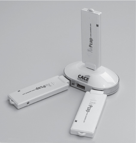
Troubleshooting roaming by using a protocol analyzer is tricky because the reassociation roaming exchanges occur on multiple channels. To troubleshoot a client roaming between channels 1, 6, and 11, you would need three separate protocol analyzers on three separate laptops that would produce three separate frame captures. Riverbed (formally CACE Technologies) offers a product called AirPcap that is a USB 802.11 radio. As you can see in Figure 7.22, three AirPcap USB radios can be configured to capture frames on channels 1, 6, and 11 simultaneously. All three radios are connected to a USB hub and save the frame captures of all three channels into a single time-stamped capture file. The AirPcap solution allows for multichannel monitoring with a single protocol analyzer.
FIGURE 7.22 AirPcap provides multichannel monitoring and roaming analysis.
Summary
The handheld WLAN devices, such as smart phones and tablets that connect to enterprise WLANs, require mobility. Layer 2 roaming mechanisms provide mobility for WLAN client devices. Over the years, seamless roaming for WLAN client devices has improved as better Layer 2 roaming mechanisms have been defined. In this chapter, you learned about the nonstandard and standard fast secure roaming operations that provide for an enhanced roaming experience. As client-side support for Voice Enterprise and 802.11k/r/v technologies grows, roaming performance will improve.
Exam Essentials
Understand legacy roaming handoff mechanisms. Reassociation is the process clients use to move from one BSS to another. Client roaming thresholds and AP-to-AP handoff communications are proprietary.
Define the operations and limitations of legacy FSR mechanisms. Explain both the PMK caching and preauthentication FSR methods defined by the 802.11-2012 standard.
Explain opportunistic key caching (OKC). Understand how the PMKID is manipulated by OKC to accomplish fast secure roaming.
Explain fast BSS transition (FT). Define all the key hierarchy components and operations defined by the 802.11r-2008 amendment.
Understand the benefits of 802.11k-2008 radio resource measurement (RRM). Describe how RRM enables client stations to make intelligent decisions to improve roaming performance.
Explain the purpose and basics of Mobile IP. Define Mobile IP components and why a Mobile IP solution is needed when clients roam across Layer 3 boundaries.
Review Questions
1. What type of solution must be deployed to provide continuous connectivity when a client station roams across Layer 3 boundaries? (Choose all that apply.)
A. Nomadic roaming solution
B. Seamless roaming solution
C. Mobile IP solution
D. Fast secure roaming solution
2. Which pairwise master key security associations (PMKSAs) can be uniquely identified by a pairwise master key identifier (PMKID)? (Choose all that apply.)
A. PMKSA derived from a PSK authentication
B. PMKSA from Open System authentication
C. Cached PMKSA from an 802.1X/EAP authentication
D. Cached PMKSA for Mobile IP authentication
E. Cached PMKSA from preauthentication
F. PMK-RO or PMK-R1 derived from fast BSS transition (FT)
3. As defined by the 802.11-2012 standard, which of these authentication methods can be used by a client station to establish a pairwise master key security association (PMKSA)? (Choose all that apply.)
A. PSK authentication
B. WEP authentication
C. 802.1X/EAP authentication
D. Open authentication
E. SAE authentication
4. Which of these methods allows an authenticator and supplicant to skip an entire 802.1X/EAP authentication and proceed with the traditional 4-Way Handshake? (Choose all that apply.)
A. PMK caching
B. PTK caching
C. Opportunistic key caching
D. Fast BSS transition
5. What is some of the operation information that an 802.11k-2008–compliant client station may receive in the neighbor report from an 802.11k-2008–compliant access point (AP)? (Choose all that apply.)
A. BSSID of neighbor AP
B. PHY types supported by neighbor AP
C. APSD support of neighbor AP
D. Channel number of neighbor AP
E. All of the above
6. Which authentication and key management (AKM) methods can also support fast BSS transition (FT)? (Choose all that apply.)
A. MAC authentication
B. 802.1X/EAP authentication
C. Open system authentication
D. SAE authentication
E. PSK authentication
7. What are some of the components that comprise a PMKID? (Choose all that apply.)
A. Authenticator MAC address
B. Authentication server MAC address
C. PMK
D. MSK
E. Supplicant MAC address
8. Which of these 802.11 management frames contain a PMKID in the RSN information element? (Choose all that apply.)
A. Reassociation request
B. Probe response
C. FT Action
D. Beacon
E. Association request
9. Within the three-tier FT key hierarchy defined by fast BSS transition, which of these keys is cached on a WLAN controller or original associated AP?
A. PMK-R1
B. MSK
C. PTK
D. PMK-R0
E. PMK
10. What are the main goals of the Wi-Fi Alliance Voice Enterprise certification? (Choose all that apply.)
A. Data traffic coexistence
B. Higher throughput
C. Voice quality
D. Video quality
E. Quality of service
11. Which of these roaming methods requires the use of FT Action frames?
A. Over-the-air fast BSS transition
B. Over-the-WDS fast BSS transition
C. Over-the-DS fast BSS transition
D. Over-the-WLS fast BSS transition
12. Within the three-tier FT key hierarchy defined by fast BSS transition (FT), which of these keys is used to encrypt the MSDU payload of an 802.11 data frame?
A. PMK-R1
B. MSK
C. PTK
D. PMK-R0
E. PMK
13. Which of these protocol adherence and performance metrics will most likely be defined by the Wi-Fi Alliance Voice Enterprise certification? (Choose all that apply.)
A. Latency
B. Jitter
C. Retry percentage
D. Consecutive lost packets
E. TCP throughput
F. Packet loss
14. Although not defined by the 802.11-2012 standard, which of these methods of fast secure roaming is supported by the majority of WLAN vendors?
A. PMK caching
B. Preauthentication
C. Opportunistic key caching
D. Over-the-air fast BSS transition
15. What aspects of roaming were not defined by the original standard? (Choose all that apply.)
A. Security
B. AP-to-AP handoff
C. PTK
D. RSSI thresholds
E. PMK
16. What is used initially to seed the FT process that is used to create three levels of key hierarchy?
A. PMK-R0
B. PMK-R1
C. PTK
D. MSK
E. PMK
17. WLAN administrator Alexandra Gunther recently upgraded her company’s WLAN infrastructure with APs that are Voice Enterprise certified. She configured the APs for fast BSS transition (FT) and deployed new iPads that also support FT. The iPads are roaming in a fast and secure manner; however, she noticed that some older laptops can no longer connect to the WLAN. What is the cause of the problem?
A. FT is not backward compatible with legacy client devices.
B. FT clients and OKC clients cannot connect to the same SSID.
C. FT and PMK caching clients cannot connect to the same SSID.
D. The laptop radio drivers cannot decipher the FT information element in the AP beacon.
18. Which of these devices serve as a key holder for the PMK-R1 key created during a fast BSS transition? (Choose all that apply.)
A. WLAN controller
B. Client stations
C. Access points
D. RADIUS server
E. Access layer switch
19. The ACME Company manufactures two models of WLAN controllers. The standard model uses the controller-based APs to encrypt and decrypt client traffic at the edge of the network. The deluxe model uses end-to-end encryption and the WLAN controller performs encryption/decryption of the client traffic at the core of the network. Which of these statements properly identify the key holder roles? (Choose all that apply.)
A. Standard model: AP is the R0KH
B. Standard model: WLAN controller is the R1KH
C. Deluxe model: WLAN controller is the R0KH
D. Deluxe model: WLAN controller is the R1KH
E. Deluxe model: AP is the R1KH
20. Which key is used to seed both over-the-air and over-the-DS fast BSS transition?
A. MSK
B. PMK-R0
C. PMK-R1
D. PTK
E. GTK