Chapter 9. Introduction to Reliefs
Despite many safety precautions within chemical plants, equipment failures or operator errors can cause increases in process pressures beyond safe levels. If pressures rise too high, they may exceed the maximum strength of pipelines and vessels. This can result in rupturing of process equipment, causing major releases of toxic or flammable chemicals.
The defense against this type of accident is to prevent the accident in the first place. Inherent safety, described in Chapter 1, is the first line of defense. The second line of defense is better process control. A major effort is always directed toward controlling the process within safe operating regions. Dangerous high-pressure excursions must be prevented or minimized.
The third line of defense against excessive pressures is to install relief systems to relieve liquids or gases before excessive pressures are developed. The relief system is composed of the relief device and the associated downstream process equipment to safely handle the material ejected.
The method used for the safe installation of pressure relief devices is illustrated in Figure 9-1. The first step in the procedure is to specify where relief devices must be installed. Definitive guidelines are available. Second, the appropriate relief device type must be selected. The type depends mostly on the nature of the material relieved and the relief characteristics required. Third, scenarios are developed that describe the various ways in which a relief can occur. The motivation is to determine the material mass flow rate through the relief and the physical state of the material (liquid, vapor, or two phases). Next, data are collected on the relief process, including physical properties of the ejected material, and the relief is sized. Finally, the worst-case scenario is selected and the final relief design is achieved.

Figure 9-1. Relief method.
Every step in this method is critical to the development of a safe design; an error in any step of this procedure can result in catastrophic failures.
In this chapter we introduce relief fundamentals and the steps in the relief design procedure. Relief sizing methods are covered in Chapter 10.
9-1. Relief Concepts
Pressure relief systems are required for the following reasons:1
• To protect personnel from the dangers of overpressurizing equipment
• To minimize chemical losses during pressure upsets
• To prevent damage to equipment
• To prevent damage to adjoining property
• To reduce insurance premiums
• To comply with governmental regulations
Typical pressure versus time curves for runaway reactions are illustrated in Figure 9-2. Assume that an exothermic reaction is occurring within a reactor. If cooling is lost because of a loss of cooling water supply, failure of a valve, or other scenario, then the reactor temperature will rise. As the temperature rises, the reaction rate increases, leading to an increase in heat production. This self-accelerating mechanism results in a runaway reaction.
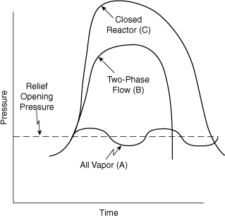
Figure 9-2. Pressure versus time for runaway reactions: (A) relieving vapor, (B) relieving froth (two-phase flow), and (C) closed reaction vessel.
The pressure within the reactor increases because of increased vapor pressure of the liquid components and/or gaseous decomposition products resulting from the high temperature.
Reaction runaways for large commercial reactors can occur in minutes, with temperature and pressure increases of several hundred degrees per minute and several hundred psi per minute, respectively. For the curves in Figure 9-2 the cooling is lost at t = 0.
If the reactor has no relief system, the pressure and temperature continue to rise until the reactants are completely consumed, as shown by curve C (Figure 9-2). After the reactants are consumed, the heat generation stops and the reactor cools; the pressure subsequently drops. Curve C assumes that the reactor is capable of withstanding the full pressure of the runaway reaction.
If the reactor has a relief device, the pressure response depends on the relief device characteristics and the properties of the fluid discharged through the relief. This is illustrated by curve A (Figure 9-2) for vapor relief only and by curve B for a two-phase froth (vapor and liquid). The pressure will increase inside the reactor until the relief device activates at the pressure indicated.
When froth is discharged (curve B in Figure 9-2), the pressure continues to rise as the relief valve opens. The incremental pressure increase over the initial relief pressure is called overpressure.
Curve A is for vapor or gas discharged through the relief valve. The pressure drops immediately when the relief device opens because only a small amount of vapor discharge is required to decrease the pressure. The pressure drops until the relief valve closes; this pressure difference is called the blowdown.
Because the relief character of two-phase vapor-liquid material is markedly different from vapor relief, the nature of the relieved material must be known in order to design a proper relief.
9-2. Definitions2
Definitions that are commonly used within the chemical industry to describe reliefs are given in the following paragraphs.
Set pressure: The pressure at which the relief device begins to activate.
Maximum allowable working pressure (MAWP): The maximum gauge pressure permissible at the top of a vessel for a designated temperature. This is sometimes called the design pressure. As the operating temperature increases, the MAWP decreases because the vessel metal loses its strength at higher temperatures. Likewise, as the operating temperature decreases, the MAWP decreases because of metal embrittlement at lower temperatures. Vessel failure typically occurs at 4 or 5 times the MAWP, although vessel deformation may occur at as low as twice the MAWP.
Operating pressure: The gauge pressure during normal service, usually 10% below the MAWP.
Accumulation: The pressure increase over the MAWP of a vessel during the relief process. It is expressed as a percentage of the MAWP.
Overpressure: The pressure increase in the vessel over the set pressure during the relieving process. Overpressure is equivalent to the accumulation when the set pressure is at the MAWP. It is expressed as a percentage of the set pressure.
Backpressure: The pressure at the outlet of the relief device during the relief process resulting from pressure in the discharge system.
Blowdown: The pressure difference between the relief set pressure and the relief reseating pressure. It is expressed as a percentage of the set pressure.
Maximum allowable accumulated pressure: The sum of the MAWP and the allowable accumulation.
Relief system: The network of components around a relief device, including the pipe to the relief, the relief device, discharge pipelines, knockout drum, scrubber, flare, or other types of equipment that assist in the safe relief process.
The relationship between these terms is illustrated in Figures 9-3 and 9-4.
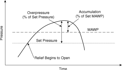
Figure 9-3. Description of overpressure and accumulation.
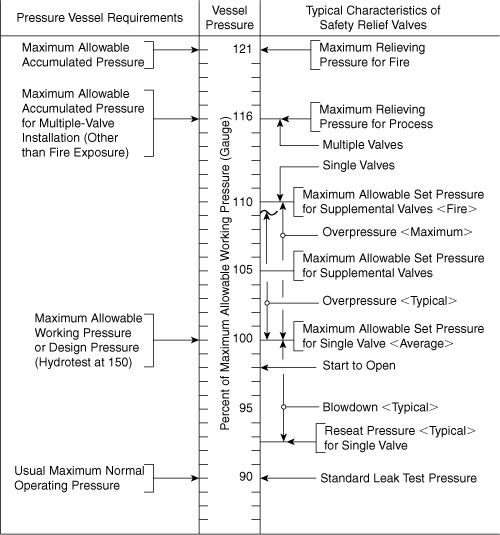
Figure 9-4. Guidelines for relief pressures. Adapted from API RP 521, Guide for Pressure-Relieving and Depressuring Systems, 4th ed. (Washington, DC: American Petroleum Institute, 1997), p. 30.
9-3. Location of Reliefs3
The procedure for specifying the location of reliefs requires the review of every unit operation in the process and of every process operating step. The engineer must anticipate the potential problems that may result in increased pressures. Pressure relief devices are installed at every point identified as potentially hazardous, that is, at points where upset conditions create pressures that may exceed the MAWP.
The types of questions asked in this review process are
• What happens with loss of cooling, heating, or agitation?
• What happens if the process is contaminated or has a mischarge of a catalyst or monomer?
• What happens if the operator makes an error?
• What is the consequence of closing valves (block valves) on vessels or in lines that are filled with liquids and exposed to heat or refrigeration?
• What happens if a line fails, for example, a failure of a high-pressure gas line into a low-pressure vessel?
• What happens if the unit operation is engulfed in a fire?
• What conditions cause runaway reactions, and how are relief systems designed to handle the discharge as a result of runaway reactions?
Some guidelines for locating reliefs are summarized in Table 9-1.
Table 9-1. Guidelines for Specifying Relief Positionsa
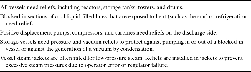
a Marx Isaacs, “Pressure-Relief Systems,” Chemical Engineering (Feb. 22, 1971), pp. 113–124.
Specify the location of reliefs in the simple polymerization reactor system illustrated in Figure 9-5. The major steps in this polymerization process include (1) pumping 100 lb of initiator into reactor R-1, (2) heating to the reaction temperature of 240°F, (3) adding monomer for a period of 3 hr, and (4) stripping the residual monomer by means of a vacuum using valve V-15. Because the reaction is exothermic, cooling during monomer addition with cooling water is necessary.
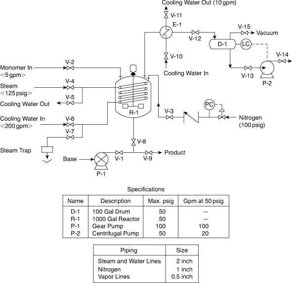
Figure 9-5. Polymerization reactor without safety reliefs.
The review method for specifying the location of reliefs follows. Refer to Figures 9-5 and 9-6 and Table 9-1 for relief locations.
a. Reactor (R-1): A relief is installed on this reactor because, in general, every process vessel needs a relief. This relief is labeled PSV-1 for pressure safety valve 1.
b. Positive displacement pump (P-1): Positive displacement pumps are overloaded, overheated, and damaged if they are dead-headed without a pressure-relieving device (PSV-2). This type of relief discharge is usually recycled back to the feed vessel.
c. Heat exchanger (E-1): Heat exchanger tubes can rupture from excessive pressures when water is blocked in (V-10 and V-11 are closed) and the exchanger is heated (by steam, for example). This hazard is eliminated by adding PSV-3.
d. Drum (D-1): Again, all process vessels need relief valves, PSV-4.
e. Reactor coil: This reactor coil can be pressure-ruptured when water is blocked in (V-4, V-5, V-6, and V-7 are closed) and the coil is heated with steam or even the sun. Add PSV-5 to this coil.
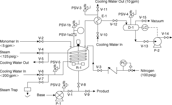
Figure 9-6. Polymerization reactor with safety reliefs.
This completes the specification of the relief locations for this relatively simple process. The reason for the two relief devices PSV-1A and PSV-1B is described in the next section.
Example 9-1 illustrates the engineering rationale for installing relief valves at various locations within a chemical plant. After the relief locations are specified, the type of relief is chosen, depending on the specific application.
9-4. Relief Types and Characteristics
Spring-Operated and Rupture Discs
Specific types of relief devices are chosen for specific applications, such as for liquids, gases, liquids and gases, solids, and corrosive materials; they may be vented to the atmosphere or vented to containment systems (scrubber, flare, condenser, incinerator, and the like). In engineering terms the type of relief device is specified on the basis of the details of the relief system, process conditions, and physical properties of the relieved fluid.
There are two general categories of relief devices (spring-operated and rupture discs) and two major types of spring-operated valves (conventional and balanced-bellows), as illustrated in Figure 9-7.
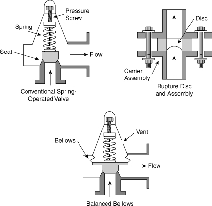
Figure 9-7. Major types of relief devices.
On spring-operated valves the adjustable spring tension offsets the inlet pressure. The relief set pressure is usually specified at 10% above the normal operating pressure. To avoid the possibility of an unauthorized person changing this setting, the adjustable screw is covered with a threaded cap.
For a conventional spring-operated relief, the valve opens based on the pressure drop across the valve seat; that is, the set pressure is proportional to the pressure drop across the seat. Thus, if the backpressure downstream of the valve increases, the set pressure will increase and the valve may not open at the correct pressure. In addition, the flow through the conventional relief is proportional to the difference in pressure across the seat. The flow through the relief, therefore, is reduced as the backpressure increases.
For the balanced-bellows design the bellows on the backside of the valve seat ensures that the pressure on that side of the seat is always atmospheric. Thus the balanced-bellows valve will always open at the desired set pressure. However, the flow through the balanced-bellows relief is proportional to the difference in pressure between the inlet and the outlet of the valve. Therefore the flow is reduced as the backpressure increases.
Rupture discs are specially designed to rupture at a specified relief set pressure. They usually consist of a calibrated sheet of metal designed to rupture at a well-specified pressure. They are used alone, in series, or in parallel to spring-loaded relief devices. They can be made from a variety of materials, including exotic corrosion-resistant materials.
An important problem with rupture discs is the flexing of the metal as process pressures change. Flexing could lead to premature failure at pressures below the set pressure. For this reason some rupture disc systems are designed to operate at pressures well below the set pressure. In addition, vacuum service may cause rupture disc failure if the relief system is not specifically designed for this service.
Another problem with rupture disc systems is that once they open, they remain open. This may lead to the complete discharge of process material. It may also allow air to enter the process, leading to a possible fire and/or explosion. In some accidents discs were ruptured without the process operator being aware of the situation. To prevent this problem, rupture discs are available with embedded wires that are cut when the disc ruptures; this can activate an alarm in the control room to alert the operator. Also, when rupture discs rupture, pieces of the disc may become dislodged, creating potential downstream plugging problems. Recent advances in rupture disc design have minimized this problem.
In all these examples the problems are eliminated if the rupture disc and system are specified and designed appropriately for the specific operating conditions of the process.
Rupture discs are available in much larger sizes than spring-operated relief valves, with commercial sizes available up to several feet in diameter. Rupture discs typically cost less than equivalently sized spring-operated relief valves.
Rupture discs are frequently installed in series to a spring-loaded relief (1) to protect an expensive spring-loaded device from a corrosive environment, (2) to give absolute isolation when handling extremely toxic chemicals (spring-loaded reliefs may weep), (3) to give absolute isolation when handling flammable gases, (4) to protect the relatively complex parts of a spring-loaded device from reactive monomers that could cause plugging, and (5) to relieve slurries that may plug spring-loaded devices.
When rupture discs are used before a spring-loaded relief, a pressure gauge is installed between the two devices. This telltale gauge is an indicator that shows when the disc ruptures. The failure can be the result of a pressure excursion or of a pinhole caused by corrosion. In either case the telltale gauge indicates that the disc needs to be replaced.
There are three subcategory types of spring-loaded pressure reliefs:
1. The relief valve is primarily for liquid service. The relief valve (liquid only) begins to open at the set pressure. This valve reaches full capacity when the pressure reaches 25% overpressure. The valve closes as the pressure returns to the set pressure.
2. The safety valve is for gas service. Safety valves pop open when the pressure exceeds the set pressure. This is accomplished by using a discharge nozzle that directs high-velocity material toward the valve seat. After blowdown of the excess pressure, the valve reseats at approximately 4% below the set pressure; the valve has a 4% blowdown.
3. The safety relief valve is used for liquid and gas service. Safety relief valves function as relief valves for liquids and as safety valves for gases.
Specify the types of relief devices needed for the polymerization reactor in Example 9-1 (see Figure 9-6).
Each relief is reviewed in relation to the relief system and the properties of the relieved fluids:
a. PSV-1a is a rupture disc to protect PSV-1b from the reactive monomers (plugging from polymerization).
b. PSV-1b is a safety relief valve because a runaway reaction will give two-phase flow, both liquid and vapor.
c. PSV-2 is a relief valve because this relief is in a liquid service line. A conventional valve is satisfactory.
d. PSV-3 is a relief valve because it is for liquid only. A conventional relief device is satisfactory in this service.
e. PSV-4 is a safety relief valve because liquid or vapor service is possible. Because this vent will go to a scrubber with possibly large backpressures, a balanced bellows is specified.
f. PSV-5 is a relief valve for liquid service only. This relief provides protection for the following scenario: The liquid is blocked in by closing all valves; the heat of reaction increases the temperature of the surrounding reactor fluid; and pressures are increased inside the coil because of thermal expansion.
After specifying the location and type of all relief devices, the relief scenarios are developed.
Buckling-Pin Reliefs
A buckling-pin relief is similar to a rupture disc; that is, when the pressure buckles the pin, the valve opens fully. As shown in Figure 9-8, this is a relatively simple device. The major advantage of a buckling-pin relief is that the pin buckles at a precise pressure, and the major disadvantage of this device is that when the pin buckles, the valve opens and stays open.
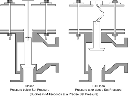
Figure 9-8. Buckling-pin relief valve.
Pilot-Operated Reliefs
The main valve of a pilot-operated relief valve is controlled by a smaller pilot valve that is a spring-operated relief valve as shown in Figure 9-9. When the pilot valve reaches the set pressure, it opens and releases the pressure above the main valve. The large valve piston then opens and exhausts the system fluid. The pilot and main valves reseat when the inlet pressure drops below the set pressure.
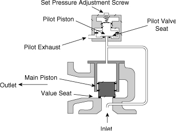
Figure 9-9. Pilot-operated relief valve.
Pilot-operated relief valves are commonly used when a large relieving area at high set pressures is required. The set pressure of this type of valve can be very close to the operating pressure. Pilot-operated valves are frequently chosen when operating pressures are within 5% of set pressures. The pilot valve exhausts either to the outlet of the main valve or to the atmosphere. Pilot-operated relief valves are commonly used in clean services.
Chatter
In general, relief systems must be designed appropriately to prevent unwanted and dangerous problems. Included in this design are the sizing of the relief and also the mechanical piping details. For example, if a system is not designed correctly, the valve may chatter violently. Chattering is the rapid opening and closing of a relief valve that can cause valve seat damage or the mechanical failure of the internals.
The major cause of valve chatter is an oversized relief valve. In this case the valve opens a short time to reduce the pressure and the pressure then rises rapidly to open the valve again. This pulsating action can be very destructive. The major causes of chatter are excessive inlet pressure drop, high backpressures, and oversized valves.
These problems have design solutions; for example, (1) excessive inlet pressure drops can be prevented with larger inlet pipe sizes and fewer elbows and constrictions; (2) high backpressures can be prevented by increasing the size of the exit lines and eliminating elbows and constrictions; and (3) oversized valves can be prevented by adding different-size valves to cover the range of release scenarios.
Advantages and Disadvantages of Various Reliefs
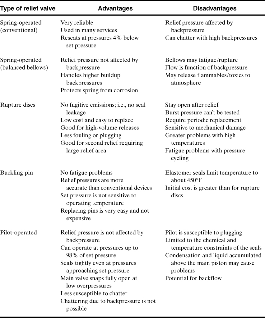
The major advantages and disadvantages of the different types of reliefs are shown in Table 9-2.
Table 9-2. Major Advantages and Disadvantages of Reliefs
9-5. Relief Scenarios
A relief scenario is a description of one specific relief event. Usually each relief has more than one relief event, and the worst-case scenario is the scenario or event that requires the largest relief vent area. Examples of relief events are
1. A pump is dead-headed; the pump relief is sized to handle the full pump capacity at its rated pressure.
2. The same pump relief is in a line with a nitrogen regulator; the relief is sized to handle the nitrogen if the regulator fails.
3. The same pump is connected to a heat exchanger with live steam; the relief is sized to handle steam injected into the exchanger under uncontrolled conditions, for example, a steam regulator failure.
This is a list of scenarios for one specific relief. The relief vent area is subsequently computed for each event (scenario) and the worst-case scenario is the event requiring the largest relief vent area. The worst cases are a subset of the overall developed scenarios for each relief.
For each specific relief all possible scenarios are identified and cataloged. This step of the relief method is extremely important: The identification of the actual worst-case scenario frequently has a more significant effect on the relief size than the accuracy of relief sizing calculations.
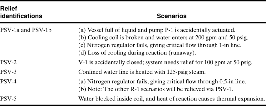
The scenarios developed for the reactor system described in Figure 9-6 are summarized in Table 9-3. The worst-case scenarios are identified later by means of the computed maximum relief area for each scenario and relief (see Chapter 10). In Table 9-3 only three reliefs have multiple scenarios that require the comparative calculations to establish the worst cases. The other three reliefs have only single scenarios; therefore they are the worst-case scenarios.
Table 9-3. Relief Scenarios for Example 9-2 (see Figure 9-6)
9-6. Data for Sizing Reliefs
Physical property data and sometimes reaction rate characteristics are required for making relief sizing calculations. Data estimated using engineering assumptions are almost always acceptable when designing unit operations because the only result is poorer yields or poorer quality. In the relief design, however, these types of assumptions are not acceptable because an error may result in catastrophic and hazardous failures.
When designing reliefs for gas or dust explosions, special deflagration data for the scenario conditions are required. These data are acquired with the apparatus already described in Section 6-13.
A runaway reaction is another scenario that requires special data.
It is known that runaway reactions nearly always result in two-phase flow reliefs.4 The two phases discharge through the relief system similar to a champagne and carbon dioxide mixture exiting a freshly opened bottle. If the champagne is heated before opening, the entire contents of the bottle may be “relieved.” This result has also been verified for runaway reactions in the chemical industry.
Two-phase flow calculations are relatively complex, especially when conditions change rapidly, as in a runaway reaction scenario. As a result of this complexity, special methods have been developed for acquiring relevant data and for making the relief vent sizing calculations. See Chapter 8 for a detailed discussion of these experimental methods and Chapter 10 for the sizing calculations.
9-7. Relief Systems
After the relief type has been chosen and the relief size computed, the engineer takes the responsibility for completing the design of the relief system, including deciding how to install the relief in the system and how to dispose of the exiting liquids and vapors.
Pressure-relieving systems are unique compared with other systems within a chemical plant; ideally they will never need to operate, but when they do, they must do so flawlessly. Other systems, such as extraction and distillation systems, usually evolve to their optimum performance and reliability. This evolution requires creativity, practical knowledge, hard work, time, and the cooperative efforts of the plant, design, and process engineers. This same effort and creativity are essential when developing relief systems; however, in this case the relief system development must be optimally designed and demonstrated within a research environment before the plant startup.
To develop the necessary optimum and reliable relief systems, it is essential to understand this technology. The objective of this section is to give students and design engineers the details necessary for understanding relief systems.
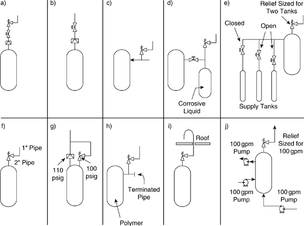
Relief Installation Practices
Regardless of how carefully the relief is sized, specified, and tested, a poor installation can result in completely unsatisfactory relief performance. Some installation guidelines are illustrated in Figure 9-10. During field construction, sometimes expediency or construction convenience leads to modifications and deviations from acceptable practice. The engineer must take the responsibility for adhering to standard practices, especially when installing relief systems.
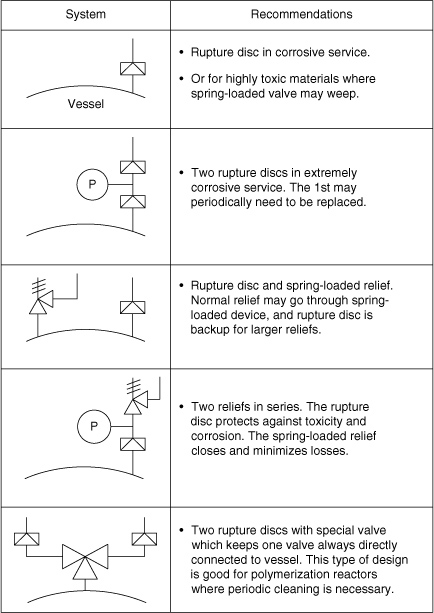
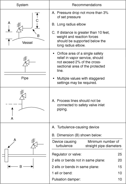
Figure 9-10. Relief installation practices. Adapted from Eric Jennett, “Components of Pressure-Relieving Systems,” Chemical Engineering (Aug. 19, 1963), pp. 151–158.
Relief Design Considerations
A designer of relief systems must be familiar with governmental codes, industrial standards, and insurance requirements. This is particularly important because local government standards may vary. Codes of particular interest are published by the American Society of Mechanical Engineers, the American Petroleum Institute, and the National Board of Fire Underwriters. Specific references have already been cited. It is recommended that relief designers carefully consider all codes and, where feasible, select the one that is most suited to the particular installation.
Another important consideration is the reaction forces generated when the relieved materials flow through the relief system at high speed. The API RP 5207 has some guidelines; however, normal stress analysis is the recommended method.
It is also important to recognize that company philosophy and the regulatory authorities have a significant influence on the design of the final disposal system, primarily from the standpoint of pollution. For this reason reliefs are now rarely vented to the atmosphere. In most cases a relief is first discharged to a knockout system to separate the liquid from the vapor; here the liquid is collected and the vapor is discharged to another treatment unit. This subsequent vapor treatment unit depends on the hazards of the vapor; it may include a condenser, scrubber, incinerator, flare, or a combination of them. This type of system is called a total containment system; one is illustrated in Figure 9-11. Total containment systems are commonly used, and they are becoming an industrial standard.
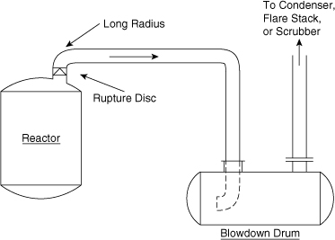
Figure 9-11. Relief containment system with blowdown drum. The blowdown drum separates the vapor from the liquid.
Horizontal Knockout Drum
Knockout drums are sometimes called catch tanks or blowdown drums. As illustrated in Figure 9-11, this horizontal knockout drum system serves as a vapor-liquid separator as well as a hold-up vessel for the disengaged liquid. The two-phase mixture usually enters at one end, and the vapor leaves at the opposite end. Inlets may be provided at each end, with a vapor exit in the center to minimize vapor velocities. When space within a plant is limited, a tangential knockout drum is used, as shown in Figure 9-12.
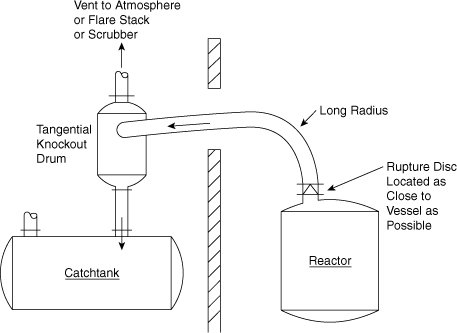
Figure 9-12. Tangential inlet knockout drum with separate liquid catch tank.
The design method for sizing this type of system was published by Grossel8 and in API 521.9 The method is based on the maximum allowable velocity for minimizing liquid entrainment. The dropout velocity of a particle in a stream is
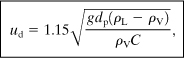
ud is the dropout velocity,
g is the acceleration due to gravity,
dp is the particle diameter,
ρL is the liquid density,
ρV is the vapor density, and
C is the drag coefficient given by Figure 9-13.
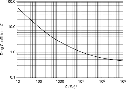
Figure 9-13. Drag coefficient correlation. Data from API RP 521, Guide for Pressure-Relieving and Depressurizing Systems, 2nd ed. (Washington, DC: American Petroleum Institute, 1982).
The abscissa of Figure 9-13 is
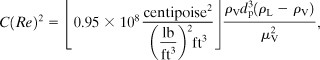
where
μV is the vapor viscosity in centipoise and
C(Re)2 is unitless.
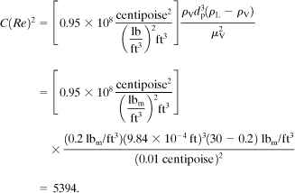
Determine the maximum vapor velocity in a horizontal knockout drum to dropout liquid particles with particle diameters of 300 μm, where
Vapor rate = 170 lb/hr,
ρV = 0.20 lb/ft3,
ρL = 30 lb/ft3,
μV = 0.01 centipoise, and
dp = 300 μm = 9.84 × 10⁻⁴ ft.
To determine the dropout velocity, the drag coefficient is first determined, using Figure 9-13. The graph abscissa is computed using Equation 9-2:
Using Figure 9-13, we find that C = 1.3.
The dropout velocity is determined by using Equation 9-1:
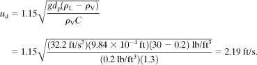
The required vapor space area, perpendicular to the vapor path, is subsequently computed using the velocity and the volumetric flow rate of the vapor. The entire vessel design is determined as a function of this vapor area plus the liquid hold volume and the general geometric configuration of the vessel.
Flares10
Flares are sometimes used after knockout drums. The objective of a flare is to burn the combustible or toxic gas to produce combustion products that are neither toxic nor combustible. The diameter of the flare must be suitable to maintain a stable flame and to prevent a blowout (when vapor velocities are greater than 20% of the sonic velocity).
The height of a flare is fixed on the basis of the heat generated and the resulting potential damage to equipment and humans. The usual design criterion is that the heat intensity at the base of the stack is not to exceed 1500 Btu/hr/ft2. The effects of thermal radiation are shown in the following table:
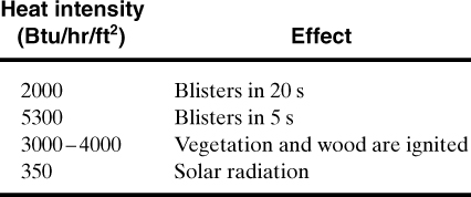
Using the fundamentals of radiation, we know that the heat intensity q at a specific point is a function of the heat generated by the flame Qf, the emissivity ε, and the distance R from the flame:
Assuming a flame height of 120df, an emissivity ![]() , and a heating value of 20,000 Btu/lb, Equation 9-3 can be algebraically modified to give the flare height Hf (in ft) as a function of the flare stack diameter df (in ft) and the desired heat intensity qf (in Btu/hr/ft2) at a distance Xf from the base of the flare (in ft) for a burning fuel with a molecular weight M and a vapor rate Qm (in lb/hr):
, and a heating value of 20,000 Btu/lb, Equation 9-3 can be algebraically modified to give the flare height Hf (in ft) as a function of the flare stack diameter df (in ft) and the desired heat intensity qf (in Btu/hr/ft2) at a distance Xf from the base of the flare (in ft) for a burning fuel with a molecular weight M and a vapor rate Qm (in lb/hr):
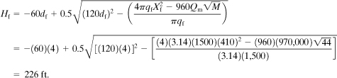
Determine the stack height required to give a heat intensity of 1500 Btu/hr/ft2 at a distance of 410 ft from the base of the flare. The flare diameter is 4 ft, the flare load is 970,000 lb/hr, and the molecular weight of the vapor is 44.
The flare height is computed using Equation 9-4. The units are consistent with those required:
Scrubbers
The fluid from reliefs, sometimes two-phase flow, must first go to a knockout system, where the liquids and vapors are separated. Liquids are subsequently collected and the vapors may or may not be vented. If the vapors are nontoxic and nonflammable, they may be vented unless some regulation prohibits this type of discharge.
If the vapors are toxic, a flare (described previously) or a scrubber system may be required. Scrubber systems can be packed columns, plate columns, or venturi-type systems. Details of scrubber designs are covered by Treybal.11
Condensers
A simple condenser is another possible alternative for treating exiting vapors. This alternative is particularly attractive if the vapors have a relatively high boiling point and if the recovered condensate is valuable. This alternative should always be evaluated because it is simple and usually less expensive and because it minimizes the volume of material that may need additional post-treatment. The design of condenser systems is covered by Kern.12
Suggested Reading
General Articles on Relief Valves and Systems
Floyd E. Anderson, “Pressure Relieving Devices,” in Safe and Efficient Plant Operations and Maintenance, Richard Greene, ed. (New York: McGraw-Hill, 1980), p. 207.
G. W. Boicourt, “Emergency Relief System (ERS) Design: An Integrated Approach Using DIERS Methodology,” Process Safety Progress (Apr. 1995), pp. 93–106.
R. Darby, Emergency Relief System Design (New York: American Institute of Chemical Engineers, 1997).
Ron Darby, “Relief Vent Sizing for Deflagrations,” Process Safety Progress (June 2006), 25(2): 130–134.
S. S. Grossel and J. F. Louvar, Design for Overpressure and Underpressure Protection (New York: American Institute of Chemical Engineers, 2000).
Marx Isaacs, “Pressure-Relief Systems,” Chemical Engineering (Feb. 22, 1971), p. 113.
Robert Kern, “Pressure-Relief Valves for Process Plants,” Chemical Engineering (Feb. 28, 1977), p. 187.
J. C. Leung, “Simplified Vent Sizing Equations for Emergency Relief Requirements in Reactors and Storage Vessels,” AICHE Journal (Oct. 1986), pp. 1622–1634.
J. C. Leung, H. K. Fauske, and H. G. Fisher, “Thermal Runaway Reactions in a Low Thermal Inertia Apparatus,” Thermochimica Acta (1986), 104: 13–29.
G. A. Melhem, “Relief System’s Last Line of Defense, Only Line of Defense?” Process Safety Progress (Dec. 2006), 25(4): 290–297.
Stanley A. Urbanik, “Evaluating Relief Valve Reliability When Extending the Test and Maintenance Interval,” Process Safety Progress (Sept. 2004), 23(3): 191–196.
Problems
9-1. Can gate valves be placed between a vessel relief and its vessel?
9-2. Describe the process of creating a vacuum in a storage vessel as a result of condensation. Develop an example to illustrate the potential magnitude of the vacuum.
9-3. In the future it is anticipated that insurance rates will be set as a function of the safety of a plant. Illustrate the kinds of plant statistics that you would cite to reduce your insurance costs.
9-4. Give four examples of situations requiring a combination of spring-operated reliefs in series with rupture discs.
9-5. PSV-2 of Figure 9-6 is a relief to protect the positive displacement pump P-1. If the fluid being handled is extremely volatile and flammable, what design modifications would you make to this relief system?
9-6. One defense against runaway reactions is better process control. Using the system illustrated in Figure 9-6, what control features (safeguards) would you add to this reactor system?
9-7. If a scrubber is installed after PSV-1b and it has a pressure drop of 30 psig, how would this affect the size (qualitatively) of this relief system?
9-8. Referring to Problem 9-7, qualitatively describe the algorithm you would use to compute the relief size for this system.
9-9. Review Figure 9-14, and determine the locations for relief devices.
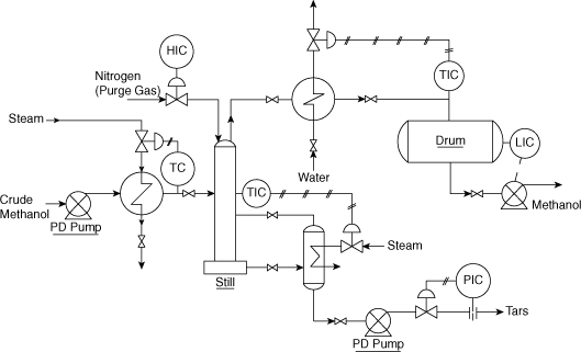
Figure 9-14. Distillation system.
9-10. Review Figure 9-15, and determine the locations for relief devices.

Figure 9-15. Extraction system.
9-11. Review Figure 9-14 and Problem 9-9 to determine what types of relief devices should be used at each location.
9-12. Review Figure 9-15 and Problem 9-10 to determine what types of relief devices should be used at each location.
9-13. Review Figure 9-14 and Problems 9-9 and 9-11, and make recommendations for total containment systems.
9-14. Review Figure 9-15 and Problems 9-10 and 9-12, and make recommendations for total containment systems.
9-15. Using the results of Problems 9-9 and 9-11, determine the relief scenarios for each relief device.
9-16. Using the results of Problems 9-10 and 9-12, determine the relief scenarios for each relief device.
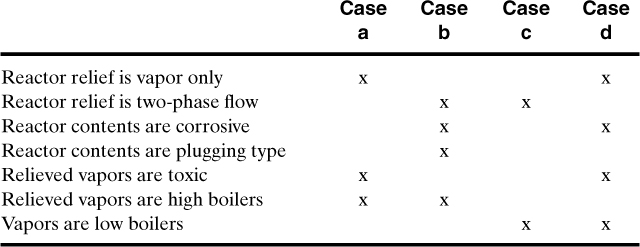
9-17. Develop sketches of reactor vent systems for the following four cases:
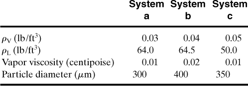
9-18. Determine the vapor velocity inside a horizontal knockout drum for the following three systems:
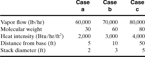
9-19. Determine the height of a flare, assuming various maximum heat intensities at ground level at the specified distances from the flare, for the following three cases:
9-20. Describe the advantages and disadvantages of a buckling pin relief valve. See Grossel and Louvar (2000).
9-21. Describe the advantages and disadvantages of a pilot-operated safety valve. See Grossel and Louvar (2000).
9-22. Describe the advantages and disadvantages of a rupture disc followed by a spring-operated relief valve. See Grossel and Louvar (2000).
9-23. When using a rupture disc followed by a spring-operated relief, it is important to periodically check the pressure gauge to be sure that there is no pinhole leak in the rupture disc. Describe several methods to satisfy this requirement.
9-24. When designing the inlet piping to a relief valve, what pressure losses are recommended? See API 520, Sizing, Selection, and Installation (1994).
9-25. The outlet piping of a relief system is normally supported to resist two mechanical stresses. What are these two stresses? See API 520, Sizing, Selection, and Installation (1994).
9-26. Sometimes isolation valves are needed between the vessel and the relief. What management system is recommended for isolation valves? See API 520, Sizing, Selection, and Installation (1994).
9-27. Describe a runaway reaction scenario that is the result of a sleeper reaction. See Grossel and Louvar (2000).
9-28. Describe a tempered runaway reaction. See Grossel and Louvar (2000).
9-29. Describe a runaway that is “gassy.” See Grossel and Louvar (2000).
9-30. Describe a runaway that is a “hybrid.” See Grossel and Louvar (2000).
9-31. Identify the problems with the relief valve configurations shown in Figure 9-16.