Chapter 7. Application Inspection
The Cisco ASA mechanisms used for stateful application inspection enforce the secure use of applications and services in your network. The stateful inspection engine keeps information about each connection traversing through the security appliance’s interfaces and makes sure they are valid. Stateful application inspection examines not only the packet header, but also the contents of the packet up through the application layer.
Several applications require special handling of data packets when they pass through the Layer 3 devices. These include applications and protocols that embed IP addressing information in the data payload of the packet or open secondary channels on dynamically assigned ports. The Cisco ASA application inspection mechanisms recognize the embedded addressing information, which allows Network Address Translation (NAT) to work and update any other fields or checksums.
Using application inspection, the Cisco ASA can identify the dynamic port assignments and allow data exchange on these ports during a specific connection. The application inspection capabilities are similar to the traditional fixup protocol functionality on the Cisco PIX firewalls. However, the Cisco ASA software dramatically enhances the capabilities of application inspection.
The following are all the applications and protocols supported by Cisco ASA:
• Computer Telephony Interface Quick Buffer Encoding (CTIQBE)
• Distributed Computing Environment Remote Procedure Calls (DCERPC)
• Domain Name Server (DNS) over UDP
• Extended Simple Mail Transfer Protocol (ESMTP)
• File Transfer Protocol (FTP)
• General Packet Radio Service Tunneling Protocol (GTP)
• H.323
• Hypertext Transfer Protocol (HTTP)
• Internet Control Message Protocol (ICMP) and ICMP Error
• Integrated Library System (ILS) protocol
• Instant Messenger (IM)
• IPSec pass-through
• Media Gateway Control Protocol (MGCP)
• Multi-chassis Multilink PPP (MMP)
• NetBIOS
• Point to Point Tunneling Protocol (PPTP)
• Remote Shell (RSH)
• Real-Time Streaming Protocol (RTSP)
• Session Initiation Protocol (SIP)
• Skinny Call Control Protocol (SCCP)
• Simple Network Management Protocol (SNMP)
• SQL*Net
• SUNRPC
• Trivial File Transfer Protocol (TFTP)
• Wide Area Application Services (WAAS)
• X Display Manager Control Protocol (XDMCP)
The following sections include thorough information on how to enable application inspection and details about these applications and protocols.
Note
Certain protocol inspection requires a separate license. An example is GTP. More licensing information can be found at http://www.cisco.com/go/asa.
Enabling Application Inspection
Cisco ASA provides a Modular Policy Framework (MPF) to provide application security or to perform quality of service (QoS) functions. MPF provides a consistent and flexible way to configure the Cisco ASA application inspection and other features in a manner similar to that used for the Cisco IOS Software Modular QoS CLI.
Note
Chapter 11, “Quality of Service,” covers the QoS functionality in detail.
As a general rule, the provisioning of inspection policies requires the following steps:
Step 1. Configuring traffic classes to identify interesting traffic.
Step 2. Associating actions to each traffic class to create service policies.
Step 3. Activating the service policies on an interface or globally.
You can complete these policy provisioning steps by using these three main commands of the MPF:
• class-map—Classifies the traffic that will be inspected. Various types of match criteria in a class map can be used to classify traffic. The primary criterion is the use of an access control list (ACL). Example 7-1 demonstrates this.
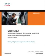
Example 7-1 Matching Specific Traffic Using an ACL
• policy-map—Configures security or QoS policies. A policy consists of a class command and its associated actions. Additionally, a policy map can contain multiple policies.
• service-policy—Activates a policy map globally (on all interfaces) or on a targeted interface.
In Example 7-1, an ACL named tftptraffic is configured to identify all UDP traffic. This ACL is then applied to a class map named TFTPclass.
A policy map named tftppolicy is configured that has the class map TFTPclass mapped to it. The policy map is set up to inspect all TFTP traffic from the UDP packets that are being classified in the class map. Finally, the service policy is applied globally.
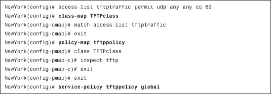
The security appliance contains a default class map named inspection_default and a policy map named tftppolicy. Example 7-2 shows the default class map and policy map in the Cisco ASA.
Example 7-2 Default Class and Policy Maps
If using the Cisco ASDM, navigate to Configuration > Firewall > Service Policy Rules to edit or create a new service policy for application inspection. Steps on how to configure each application inspection parameter are shown later in this chapter.
Selective Inspection
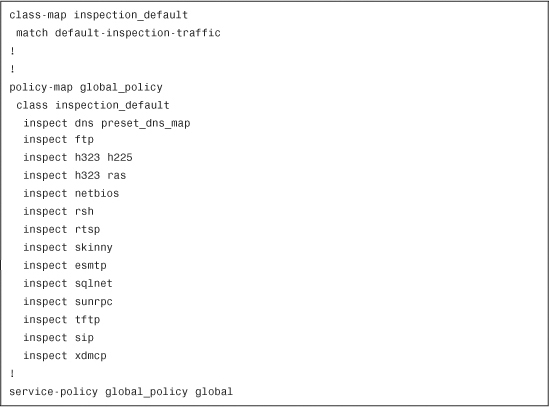
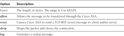
As previously mentioned, the match command enables you to specify what traffic the Cisco ASA inspection engine is to process. It can be used in conjunction with an ACL to determine what traffic is to be inspected. Example 7-3 shows all the supported options for traffic classification in a class map named UDPclass.
Example 7-3 Supported Traffic Classification Options
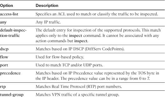
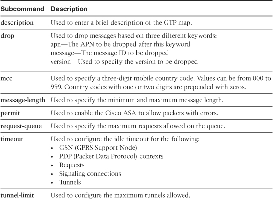
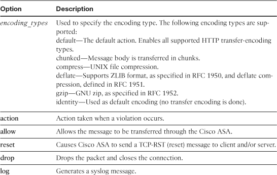
Table 7-1 lists briefly describes all the options supported by the match command.
Table 7-1 match Subcommand Options
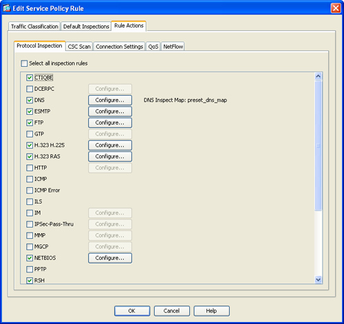
If using ASDM, you can configure traffic classification by navigating to Configuration > Firewall > Service Policy Rules and clicking on Edit to edit a service policy. The Edit Service Policy Rule dialog box shown in Figure 7-1 is displayed.
Figure 7-1 Service Policy Traffic Classification
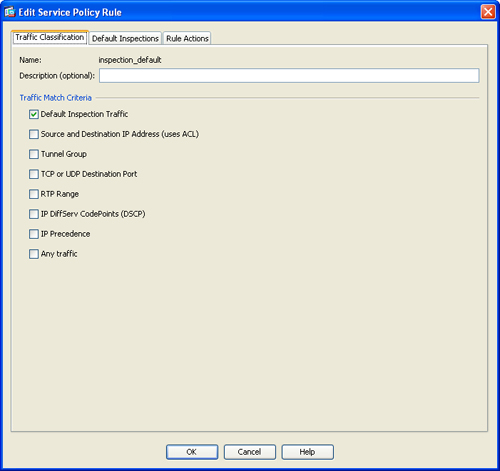
In this figure you can see the corresponding options for traffic classification on ASDM.
To display statistics on the traffic being inspected on the Cisco ASA, use the show service-policy command. Example 7-4 shows the output of this command.
Example 7-4 Output of show service-policy Command
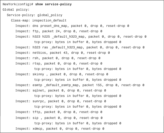
The show service-policy flow command is also very useful because it can be used to display traffic flow information for a specific protocol flow. The following sections include information about each application inspection protocol supported on Cisco ASA.
Computer Telephony Interface Quick Buffer Encoding Inspection
Some Cisco Voice over IP (VoIP) applications use the Telephony Application Programming Interface (TAPI) and Java TAPI (JTAPI). TAPI-compatible applications can run on a wide variety of PC and telephony hardware and can support a variety of network services. The Cisco TAPI Service Provider (TSP) uses the Computer Telephony Interface Quick Buffer Encoding (CTIQBE) to communicate with Cisco CallManager on TCP port 2748. Figure 7-2 illustrates how CTIQBE works.
Figure 7-2 Explanation of CTIQBE
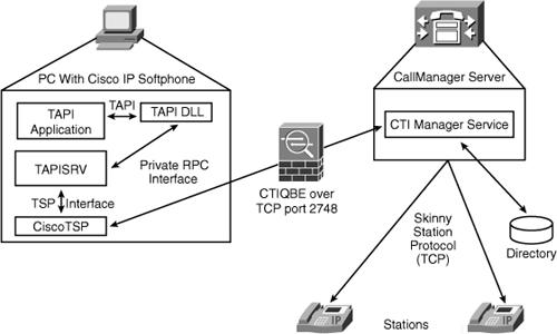
In Figure 7-2, a PC with Cisco IP SoftPhone communicates with a Cisco CallManager. CTIQBE inspection is not enabled by default.
Complete the following steps to enable CTIQBE inspection via ASDM:
Step 1. Log in to ASDM and navigate to Configuration > Firewall > Service Policy Rules.
Step 2. Click on Edit to edit a service policy. The Edit Service Policy Rule dialog box shown in Figure 7-3 is displayed.
Figure 7-3 Enabling CTIQBE Inspection
Step 3. Click on the Rule Actions tab.
Step 4. Select CTIQBE.
Step 5. Click OK.
Step 6. Click Apply to apply the configuration changes.
Step 7. Click Save to save the configuration in the Cisco ASA.
Note
The Edit Service Policy Rule dialog box can be used to enable or disable any other application inspection protocols.
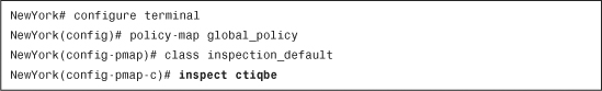
If configuring the Cisco ASA via the CLI, use the inspect ctiqbe command to enable CTIQBE inspection, as shown in Example 7-5.
Example 7-5 Enabling CTIQBE Inspection
Note
CTIQBE application inspection is not supported if the alias command is present in the configuration.
Tip
CTIQBE calls fail if two Cisco IP SoftPhones are registered with different Cisco CallManagers connected to different interfaces of the Cisco ASA.
Tip
If the Cisco CallManager IP address is to be translated and you are also using PAT, TCP port 2748 must be statically mapped to the same port as that of the PAT (interface) address for Cisco IP SoftPhone registrations to succeed. The CTIQBE listening port (TCP 2748) is fixed and is not configurable on Cisco CallManager, Cisco IP SoftPhone, or Cisco TSP.
Note
Stateful failover of CTIQBE calls is not supported.
You can use the show conn state ctiqbe command to display the status of CTIQBE connections. The C flag represents the media connections allocated by the CTIQBE inspection engine. Example 7-6 includes the output of the show conn state ctiqbe command.
Example 7-6 Output of the show conn state ctiqbe Command
![]()
Distributed Computing Environment Remote Procedure Calls (DCERPC)
DCERPC is a protocol that allows programmers to write distributed software without having to worry about the underlying network code. It is widely used by Microsoft distributed client and server applications. The Cisco ASA allows the appropriate port number and network address and also applies NAT, if needed, for the secondary connection. DCERPC inspect maps inspect for native TCP communication between the EPM and client on well-known TCP port 135.
To enable DCERPC inspection with ASDM, navigate to Configuration > Firewall > Service Policy Rules and edit the respective service policy. Then select DCERPC under the Rule Actions in the Edit Service Policy Rule dialog box shown in Figure 7-3.
If configuring the Cisco ASA via the CLI, use the inspect dcerpc command to enable DCERPC inspection, as shown in Example 7-7.
Example 7-7 Enabling DCERPC Inspection

Domain Name System
Domain Name System (DNS) implementations require application inspection so that DNS queries don’t have to rely on the generic UDP handling based on activity timeouts. As a security mechanism, the UDP connections associated with DNS queries and responses are torn down as soon as a reply to a DNS query has been received in the Cisco ASA. This is similar to the old DNS Guard feature in Cisco PIX Firewall.
Cisco ASA DNS inspection provides the following benefits:
• Guarantees that the ID of the DNS reply matches the ID of the DNS query.
• Allows the translation of DNS packets through the use of NAT.
• Reassembles the DNS packet to verify its length. The Cisco ASA allows DNS packets of up to 65,535 bytes. When necessary, reassembly is done to verify that the packet length is less than the maximum length specified by the user. The packet is dropped if it is not compliant.
To enable DNS inspection via ASDM, select DNS under the Edit Service Policy Rule dialog box previously shown in Figure 7-3. You can also configure several optional parameters for this DNS inspection by clicking on the Configure button. The Select DNS Inspect Map is displayed. To configure a new DNS inspect map, click on Add. The dialog box shown in Figure 7-4 is displayed.
Figure 7-4 Adding a DNS Inspect Map
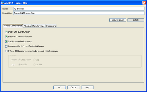
To configure the protocol conformance settings for DNS, select the Protocol Conformance tab, as shown in Figure 7-4. The following options are available:
• Enable DNS Guard Function—This option enables the Cisco ASA to do a DNS query-and-response mismatch check, using the identification field within the header of the DNS packet.
• Enable NAT Re-write Function—The Cisco ASA performs IP address translation in the A record of the DNS response.
• Enable Protocol Enforcement—The Cisco ASA performs a DNS message-format check, including the following:
• Domain name
• Label length
• Compression
• Looped pointer check
• Randomize the DNS Identifier for DNS Query—Select this to randomize the DNS identifier in the DNS query message.
• Enforce TSIG Resource Record to Be Present in DNS Message—The Cisco ASA enforces that a TSIG resource record be present in DNS transactions. The Cisco ASA can either drop the packet or log associated messages, depending on what you configure in the Actions section.
The Filtering tab enables you to configure the filtering settings for DNS, as shown in Figure 7-5.
Figure 7-5 DNS Inspect Map Filtering Tab
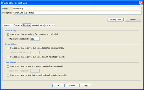
Under the Global Settings section you can enable the Cisco ASA to drop packets that exceed specified maximum length (globally). You can specify the maximum packet length (in bytes) under the Maximum Packet Length field.
The Server Settings section enables you to configure server specific parameters. The Client Settings section enables you to configure client-specific parameters. The following options are available for both:
• Drop packets that exceed specified maximum length
• Drop packets sent to server that exceed length indicated by the Resource Record (RR)
The Mismatch Rate tab enables you configure the ID mismatch rate for DNS, as shown in Figure 7-6.
Figure 7-6 DNS Inspect Map Mismatch Rate Tab
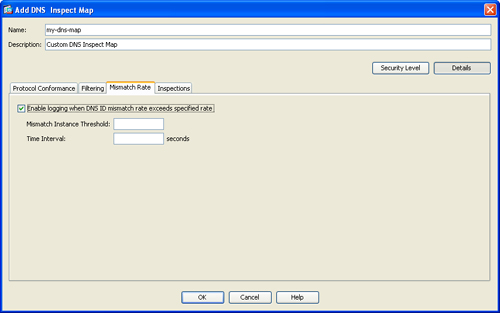
Click the Enable Logging when DNS ID Mismatch Rate Exceeds Specified Rate to enable logging on the Cisco ASA when excessive instances of DNS identifier mismatches are received. You can specify the maximum number of mismatch instances before logging is performed under the Mismatch Instance Threshold field. Use the Time Interval field to configure the time period (in seconds) to monitor.
The Inspections tab enables you add or edit more granular matching parameters and actions to be taken. Click on Add to add a new matching criteria or Edit to edit an existing one. The Add DNS Inspect dialog box shown in Figure 7-7 is displayed.
Figure 7-7 Add DNS Inspect Dialog Box
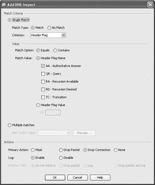
The following options are available under the Match Criteria section:
• The Match Type field enables you to configure a positive or negative match based on a specific criterion.
• The Criterion field enables you to select the criterion of the DNS inspection. You can match based on the header flag, type, class, question, resource record, or based on a domain name.
• The Value section enables you to configure the value to match in the DNS inspection.
• Similarly, you can also configure multiple matches under the Multiple matches field.
The Action section enables you to configure the action to be taken by the Cisco ASA if the match condition is met.
The primary action can be configured to mask, drop the offending packet, drop the connection, or take no action. Logging can also be enabled. Additionally, when TSIG enforcement is enabled, you can drop the packet, enable logging, or do both.
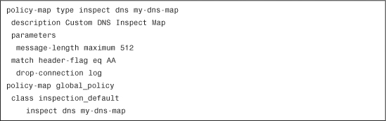
If you are using the CLI, use the inspect dns command. Example 7-8 includes the CLI commands for the parameters configured via ASDM in the previous examples.
Example 7-8 Enabling DNS Inspection
Extended Simple Mail Transfer Protocol
Cisco ASA Extended SMTP (ESMTP) inspection enhances the traditional SMTP inspection provided by Cisco PIX Firewall version 6.x or earlier. It provides protection against SMTP-based attacks by restricting the types of SMTP commands that can pass through the Cisco ASA. The following are the supported ESMTP commands:
• AUTH
• DATA
• EHLO
• ETRN
• HELO
• HELP
• NOOP
• QUIT
• RCPT
• RSET
• SAML
• SEND
• SOML
• VRFY
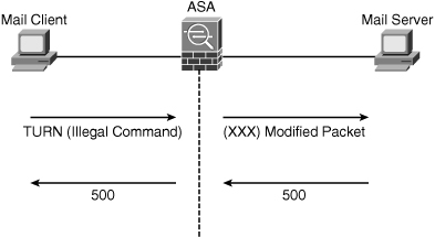
If an illegal command is found in an ESMTP or SMTP packet, it is modified and forwarded. This causes a negative server reply, forcing the client to issue a valid command. Figure 7-8 shows an example in which a user is trying to send TURN, which is an unsupported illegal command. The Cisco ASA modifies it and makes the receiver reply with an SMTP error return code of 500 (command not recognized) and tears down the connection.
Note
The Cisco ASA replaces the illegal command characters with X’s, as illustrated in Figure 7-8.
Figure 7-8 ESMTP Illegal Command Example
The Cisco ASA may perform deeper parameter inspection for packets containing legal commands. This type of inspection is required for SMTP and ESMTP extensions. Deeper parameter inspection is used to inspect the following SMTP and ESMTP extensions:
• Message Size Declaration (SIZE)
• Remote Queue Processing Declaration (ETRN)
• Binary MIME (BINARYMIME)
• Command Pipelining (PIPELINING)
• Authentication (AUTH)
• Delivery Status Notification (DSN)
To enable ESMTP inspection via ASDM, navigate to Configuration > Firewall > Service Policy Rules > Edit Service Policy Rule and select ESMTP under the Edit Service Policy Rule dialog box (previously shown in Figure 7-3). You can also configure several optional parameters for this ESMTP inspection by clicking on the Configure button. The Select ESMTP Inspect Map dialog box is displayed.
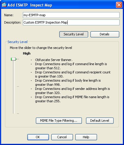
To configure a new ESMTP inspect map, click on Add. The Add ESMTP Inspect Map dialog box shown in Figure 7-9 is displayed.
Figure 7-9 Adding an ESMTP Inspect Map
There are three different security levels: high, medium, or low. Low is the default and includes the following checks and actions:
• Log if command line length is greater than 512
• Log if command recipient count is greater than 100
• Log if body line length is greater than 1000
• Log if sender address length is greater than 320
• Log if MIME file name length is greater than 255
When you select Medium for the security level, the following checks and actions are performed:
• Obfuscate Server Banner
• Drop Connections if command line length is greater than 512
• Drop Connections if command recipient count is greater than 100
• Drop Connections if body line length is greater than 1000
• Drop Connections if sender address length is greater than 320
• Drop Connections if MIME file name length is greater than 255
When you select High for the security level the following checks and actions are performed:
• Obfuscate Server Banner
• Drop Connections if command line length is greater than 512
• Drop Connections if command recipient count is greater than 100
• Drop Connections if body line length is greater than 1000
• Drop Connections and log if sender address length is greater than 320
• Drop Connections and log if MIME file name length is greater than 255
The MIME File Type Filtering button enables you to configure MIME file type filters that can be defined by custom regular expressions.
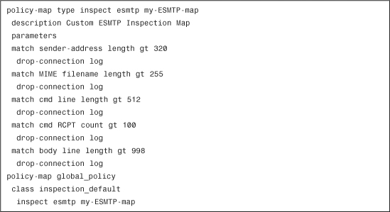
To enable ESMTP inspection via the CLI, use the inspect esmtp command. This command is enabled in the default class and policy maps on the Cisco ASA. Example 7-9 shows the CLI configuration when the ESTMP inspect map security level was set to High in ASDM.
Example 7-9 Enabling ESMTP Inspection via the CLI
File Transfer Protocol
Cisco ASA FTP application inspection examines the FTP sessions to provide the following features:
• Enhanced security while creating dynamic secondary data connections for FTP transfers
• Enforcement of FTP command-response sequence
• Generation an audit trail for FTP sessions
• Translation of embedded IP address
To enable FTP inspection via ASDM, navigate to Configuration > Firewall > Service Policy Rules > Edit Service Policy Rule and select FTP under the Edit Service Policy Rule dialog box. You can also configure several optional parameters for this FTP inspection by clicking the Configure button. The Select FTP Inspect Map dialog box is displayed.
To configure FTP inspection via the CLI, use the inspect ftp command to enable FTP inspection. The strict keyword (optional) enables the Cisco ASA to prevent client systems from sending embedded commands in FTP requests:
inspect ftp [strict] ftp-map-name
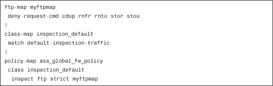
ftp-map-name is the name of an FTP map used to define FTP request commands to be denied. Example 7-10 demonstrates how to use the inspect ftp strict command in conjunction with an FTP map, called myftpmap, to deny several FTP commands.
Example 7-10 Denying Specific FTP Commands
Note
The strict option may break FTP sessions from clients that do not comply with the RFC standards; however, it provides more security features.
When the strict option is enabled, the following anomalous activities in FTP commands and replies are denied:
• The total number of commas in the PORT and PASV reply commands is checked. If they are not 5, the PORT command is considered to be truncated and the connection is closed.
• The Cisco ASA inspects all FTP commands to see whether they end with <CR><LF> characters, as specified by the RFC 959, “FTP Protocol.” The connection is closed if these are not present.
• The PORT command is always expected to be sent from the FTP client. If the PORT command is sent from the server, the connection is dropped.
• The PASV reply command is always expected to be sent from the server. If the PASV command is sent from the client, the connection is dropped.
• The Cisco ASA checks the negotiated dynamic port value in the passive FTP mode. The port should not be in the range from 1 to 1024. These are reserved for well-known protocols. The connection is closed if the negotiated port is within this range.
• The security appliance checks the number of characters included after the port numbers in the PORT and PASV reply commands. The maximum number of characters must be eight. The Cisco ASA closes the TCP connection if the number of characters exceeds eight.
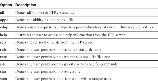
The FTP map request-command deny subcommand is used to deny specific FTP commands on the Cisco ASA. Table 7-2 lists all the request-command deny subcommand options that can be restricted under an FTP map.
Table 7-2 List of FTP Commands Available for Restriction
The SYST FTP command allows a system to ask for information about the server’s operating system. The server accepts this request with code 215 and sends the requested information. The Cisco ASA replaces the FTP server response to the SYST command with an X for each character sent, to prevent FTP clients from seeing the FTP server system–type information. You can use the no mask-syst-reply subcommand in FTP map configuration mode to disable this default behavior, as shown in Example 7-11.
Example 7-11 mask-syst-reply Subcommand
![]()
General Packet Radio Service Tunneling Protocol
The General Packet Radio Service (GPRS) is a new carrier service for Global System for Mobile Communication (GSM) that enhances and simplifies wireless access to packet data networks. GPRS architecture uses a radio-packet technique to transfer user data packets in an efficient way between GSM mobile stations and external data networks.
The GPRS Tunneling Protocol (GTP) enables multiprotocol packets to be tunneled through a GPRS backbone.
Figure 7-10 illustrates a basic representation of the GPRS architecture.
Figure 7-10 GPRS Architecture Example
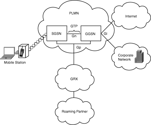
This figure shows a mobile station (MS) logically connected to an SGSN. The SGSN provides data services to the MS. The SGSN is logically connected to a GGSN via GTP. If the GTP tunnel connection is over the same Public Land Mobile Network (PLMN), the interface connecting the tunnel is called the Gn interface. Connections between two different PLMNs are known as the Gp interfaces. The GGSN acts as a gateway to external networks such as the Internet or the corporate network via the Gi interface. In other words, the interface between a GGSN and an SGSN is called Gn, whereas the interface between the GGSN and an external data network is called Gi. GTP encapsulates data from the mobile station and controls the establishment, movement, and deletion of tunnels between SGSN and GGSN in roaming scenarios.
There are two versions of GTP:
• GTPv0
• GTPv1
GTPv0
In GTPv0, the GPRS mobile stations are connected to a SGSN without knowing GTP. A Packet Data Protocol (PDP) context is identified by the tunnel identifier (TID), which is a combination of the International Mobile Subscriber Identity (IMSI) and Network Service Access Point Identifier (NSAPI). The mobile stations can have up to 15 NSAPIs each. This allows the mobile stations to create multiple PDP contexts with different NSAPIs. These NSAPIs are based on application requirements for different QoS levels.
The common transport protocol for signaling messages for GTPv0 and v1 is UDP. GTPv0 can allow the use of TCP for the transport protocol data units (TPDUs). The Cisco ASA supports only UDP. The UDP destination port for requests is port 3386.
Figure 7-11 illustrates call flow and the signaling messages involved for GTPv0.
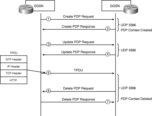
The following is the sequence of events in the call flow shown in Figure 7-11:
Step 1. The SGSN sends a create PDP request to the GGSN.
Step 2. The PDP context is created and the GGSN sends a PDP response back to the SGSN.
Step 3. The SGSN sends an update PDP request message to the GGSN.
Step 4. The GGSN replies back.
Step 5. TPDUs are sent by the SGSN. (Figure 7-4, shown previously, shows a sample of the TPDU as seen by the Cisco ASA inspection engine.)
Step 6. The SGSN sends a request to delete the PDP context.
Step 7. The PDP context is deleted and the GGSN sends its deletion response.
GTPv1
GTPv1 supports primary and secondary contexts for mobile stations. The primary context is identified with an IP address. Secondary contexts are created that share the IP address and other parameters already associated with the primary context. The advantage of this technique is that the mobile station is able to initiate a connection to a context with different QoS requirements, while also sharing the IP address obtained for the primary context.
GTPv1 uses UDP port 2123 for requests and UDP port 2152 for data transfer.
Figure 7-12 illustrates call flow and the signaling messages involved for GTPv1.
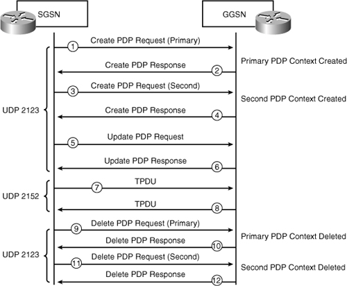
The following is the sequence of events in the call flow shown in Figure 7-12:
Step 1. The SGSN sends a PDP context create request for the primary PDP context.
Step 2. The primary context is created and the GGSN sends its response.
Step 3. The SGSN sends a PDP context create request for the second PDP context.
Step 4. The second context is created and the GGSN sends its response.
Step 5. The SGSN sends a PDP update request to the GGSN.
Step 6. The GGSN replies back with a PDP update response.
Step 7. TPDU (data packets) are sent to the GGSN.
Step 8. TPDU (data packets) are sent to the SGSN.
Step 9. The SGSN sends a request to delete the primary PDP context.
Step 10. The primary PDP context is deleted and the GGSN sends its response.
Step 11. The SGSN sends a request to delete the second PDP context.
Step 12. The second PDP context is deleted and the GGSN sends its response.
Figure 7-13 illustrates the Cisco ASA positioned between GPRS networks.
Figure 7-13 Cisco ASA in GPRS Network

In Figure 7-13, the Cisco ASA is positioned between two GPRS PLMNs. This exemplifies how a mobile station may move from its home PLMN (HPLMN) to a visited PLMN (VPLMN) and communication will still be possible through the Cisco ASA. The Cisco ASA inspects all traffic between the respective SGSNs and GGSNs.
Configuring GTP Inspection
To enable GTP inspection via ASDM, navigate to Configuration > Firewall > Service Policy Rules > Edit Service Policy Rule and select GTP under the Edit Service Policy Rule dialog box. You can also configure several optional parameters for this GTP inspection by clicking on the Configure button. The Select GTP Inspect Map dialog box is displayed.
There is only one security level setting for GTP inspection (low) and the following parameters are set:
• Do not Permit Errors
• Maximum Number of Tunnels: 500
• GSN timeout: 00:30:00
• Pdp-Context timeout: 00:30:00
• Request timeout: 00:01:00
• Signaling timeout: 00:30:00
• Tunnel timeout: 01:00:00
• T3-response timeout: 00:00:20
• Drop and log unknown message IDs
To configure IMSI prefix filters, click on the MSI Prefix Filtering button. The IMSI Prefix Filtering dialog box enables you to configure the IMSI prefix to allow within GTP requests. The following options are available:
• Mobile Country Code—Non-zero, three-digit value identifying the mobile country code.
• Mobile Network Code—Two- or three-digit value identifying the network code.
The Add and Delete buttons enable you to add or delete the specified country code and network code to the IMSI Prefix table.
To enable GTP inspection, use the inspect gtp command. You can also associate a GTP map to create a more customizable configuration. This provides granular control of various GTP parameters and filtering options.
Note
GTP inspection is not supported with NAT or PAT. GTP inspection requires a special license from Cisco. For more information about licensing go to Cisco’s website at www.cisco.com/go/nac.
You can create a GTP map by using the gtp-map command, followed by the name of the map. Example 7-12 demonstrates how the Cisco ASA is configured with a GTP map, called mygtpmap, to enforce different restrictions.
Example 7-12 GTP Inspection Example
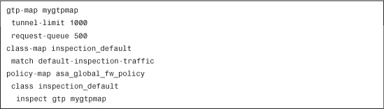
In Example 7-12, the Cisco ASA allows a maximum of only 1000 GTP tunnels and allows a maximum of only 500 requests to be queued. The GTP map is mapped to the default policy map under the default inspection class.
Table 7-3 lists all the subcommands available to configure under a GTP map.
H.323
The H.323 standard stipulates the components, protocols, and procedures that provide multimedia communication services (audio, video, and data) over IP-based networks. H.323 is defined in RFC 3508. Four kinds of H.323 components provide point-to-point and point-to-multipoint multimedia communication services:
• Terminals—Endpoints on the network that provide real-time two-way communications, such as Cisco IP Phones.
• Gateways—Provide translation between circuit-switched networks and packet-based networks, enabling the endpoints to communicate.
• Gatekeepers—Responsible for call control and routing services to H.323 endpoints, system management, and some security policies.
• Multipoint control units (MCUs)—Maintain all the audio, video, data, and control streams between all the participants in the conference.
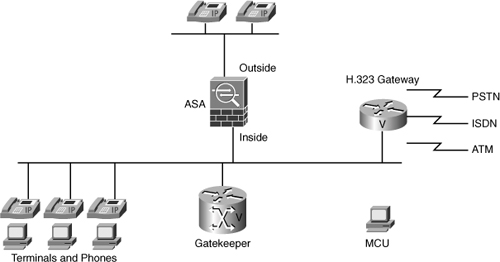
Figure 7-14 shows a basic network topology that illustrates the components of an H.323 network.
Figure 7-14 H.323 Network Components
H.323 Protocol Suite
The following are the main H.323 components illustrated in Figure 7-15:
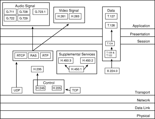
• The G.7xx components are audio codecs.
• The H.26x components are video codecs. The standard is H.261.
• Audio and video components sit on top of the Real-Time Transport Protocol (RTP).
• The T.12x protocols are used in real-time exchange of data. One example is an online whiteboard application.
In Figure 7-15, the protocols are illustrated in relation to the respective OSI layers.
The H.323 suite of protocols may use up to two TCP connections and four to six UDP connections:
• RTP uses the Real-Time Transport Control Protocol (RTCP) to control and synchronize streaming audio and video. It allows the application to adapt the flow to specific network conditions.
• Terminals and gatekeepers use the Registration, Admission, and Status (RAS) Protocol to exchange information about call registrations, admissions, and terminations. This protocol communicates over UDP.
Note
The FastConnect H.323 feature uses only one TCP connection, and RAS uses UDP requests and responses for registration, admissions, and status.
• H.225 is a protocol used to establish connections between two terminals. It runs over TCP.
• H.245 is a protocol used between two terminals to exchange control messages. These messages include flow control and channel management commands.
• Clients may request a Q.931 call setup over TCP port 1720 to H.323 servers. During the call setup process, the H.323 terminal provides the TCP port number for the client to use for an H.245 connection.
Note
The initial packet is transmitted over UDP if H.323 gatekeepers are used.
• The Cisco ASA can monitor the Q.931 TCP connection to determine the H.245 port number. It dynamically allocates the H.245 connection based on the inspection of the H.225 messages if FastConnect is not used.
• The terminals negotiate the port numbers to be used for subsequent UDP streams within each H.245 message. The Cisco ASA also monitors the H.245 messages to know about these ports and to create the necessary connections.
RTP uses the negotiated port number; however, RTCP uses the next higher port number.
The following are the key TCP and UDP ports in H.323 inspection:
• Gatekeeper discovery—UDP port 1718
• RAS—UDP port 1719
• Control port—TCP port 1720
H.323 Version Compatibility
Cisco ASA is compatible with H.323 versions 1, 2, 3, and 4.
Note
The H.323 inspection support must not be confused with the Cisco Unified Communications (UC) advanced support. Cisco UC advanced support is covered in detail later in this chapter in the “Unified Communications Advanced Support” section.
Figure 7-16 and Figure 7-17 show a major difference between older versions of H.323 and H.323v3 and higher.
Figure 7-16 Call Setup Pre H.323v3
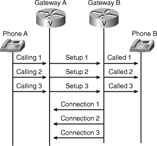
Figure 7-17 H.323v3 Call Setup Features
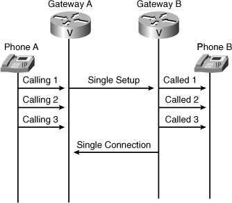
H.323v3 and higher supports multiple calls on one signaling connection. It accomplishes this by examining the call reference value (CRV) within the Q.931 message, as shown in Figure 7-10. This results in reduced call setup and clearing times.
Enabling H.323 Inspection
To enable H.323 inspection via ASDM for H.225, navigate to Configuration > Firewall > Service Policy Rules > Edit Service Policy Rule and select H.323 H.225 under the Edit Service Policy Rule dialog box. You can also configure several optional parameters for this H.323 H.225 inspection by clicking on the Configure button. The Select H.232 Inspect Map dialog box is displayed. Click on Add to add a new inspection map or use the default H.323 inspection map parameters. When adding a new H.323 inspection map, you can configure three different security levels (low, medium, or high).
The low is the default and supports the following checks and actions:
• State Checking H.225 disabled
• State Checking RAS disabled
• Call Party Number disabled
• Call Duration Limit disabled
• RTP Conformance not enforced
The medium security level supports the following checks and actions:
• State Checking H.225 enabled
• State Checking RAS enabled
• Call Party Number disabled
• Call Duration Limit disabled
• RTP Conformance enforced
• Does not limit payload to audio or video, based on the signaling exchange
The high security level supports the following checks and actions:
• State Checking H.225 enabled
• State Checking RAS enabled
• Call Party Number enabled
• Call Duration Limit 1:00:00
• RTP Conformance enforced
• It adds support to limit payload to audio or video, based on the signaling exchange
The Phone Number Filtering button enables you to configure the settings for a phone number filter.
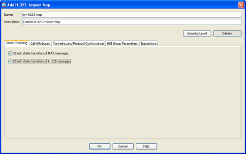
You can configure additional settings for H.323 application inspection maps by clicking on the Details button.
The State Checking tab enables you to configure state checking parameters for the H.323 inspection map. The following options are available:
• Check State Transition of H.225 Messages—Used to enforce H.323 state checking on H.225 messages.
• Check State Transition of RAS Messages—Used to enforce H.323 state checking on RAS messages.
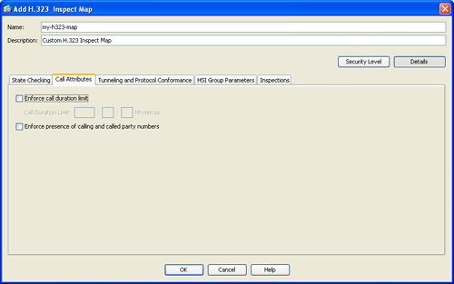
The Call Attributes tab is where you configure call attribute parameters for the H.323 inspection map.
The following options are available:
• Enforce Call Duration Limit—Used in combination with the Call Duration Limit field.
• Enforce Presence of Calling and Called Party Numbers—Used to enforce the presence of “calling” and “called” party numbers.
The Tunneling and Protocol Conformance tab is where you configure tunneling and protocol conformance parameters for the H.323 inspection map. The following options are available:
• Check for H.245 Tunneling—Enables you to check for H.245 tunneling and to drop a connection or perform logging.
• Check RTP Packets for Protocol Conformance—Used to check RTP/RTCP packets on the pinholes for protocol conformance. This can be used in combination with the Limit Payload to Audio or Video, Based on the Signaling Exchange option to enforce the payload type to be audio or video based on the signaling exchange.
The HSI Group Parameters tab enables you to configure an HSI group. In the Inspections tab you add or edit advanced matching parameters for H.323 inspection, using regular expressions.
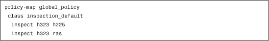
To enable H.323 inspection for H.225, use the inspect h323 h225 command. For RAS, use the inspect h323 ras command. Example 7-13 shows both commands.
Example 7-13 H.323 Inspection Commands
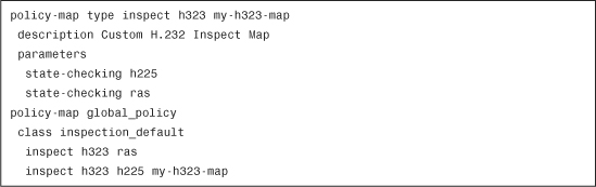
Example 7-14 shows the commands sent by ASDM to the Cisco ASA in the previous examples.
Example 7-14 H.323 Inspection Commands Sent by ASDM
The Cisco ASA can translate the necessary embedded IP addresses in the H.225 and H.245 packets. It also can translate H.323 connections. It uses an ASN.1 decoder to decode the H.323 Packet Encoding Rules (PER) encoded messages. The Cisco ASA also dynamically allocates the negotiated H.245, RTP, and RTCP sessions.
Additionally, the Cisco ASA analyzes the TPDU Packet (TPKT) header to define the length of the H.323 messages. In H.323, Q.931 messages are exchanged over a TCP stream demarcated by TPKT encapsulations. It maintains a data structure for each connection that also contains the TPKT length for the H.323 messages to be received.
Note
Cisco ASA supports segmented TPKT messages.
Direct Call Signaling and Gatekeeper Routed Control Signaling
Two control-signaling methods are defined in the ITU-T H.323 recommendation:
• Direct Call Signaling (DCS)
• Gatekeeper Routed Control Signaling (GKRCS)
Cisco ASA supports both methods. The Cisco ASA inspects DSC and GKRCS to ensure that the negotiation messages and correct fields are transferred between the respective devices. GKRCS inspection is done when H.323 inspection is enabled in the Cisco ASA. No additional configuration is needed.
Note
The Cisco ASA must see the calling endpoint address within the initial H.225 setup information to allow the respective connection.
T.38
T.38 is the protocol used with Fax over IP (FoIP). This protocol is part of the ITU-T H.323 VoIP architecture. Cisco ASA supports inspection of this protocol. Because T.38 is a part of the H.323 protocol, inspection will be done if H.323 inspection is enabled on the Cisco ASA. No additional configuration is needed.
Unified Communications Advanced Support
The Cisco ASA provides advanced support for Cisco Unified Communications (UC) solutions. This advanced support includes the following solutions:
Phone Proxy
The Cisco ASA phone proxy feature provides secure remote access for Cisco encrypted endpoints (SRTP/TLS), and VLAN traversal for Cisco SoftPhones. This feature was designed to increase scalability in large deployments without a need of a large and complex VPN remote access hardware deployment.
Note
The Cisco ASA phone proxy was designed to replace the Cisco Unified Phone Proxy. For information about the differences between the TLS proxy and phone proxy go to http://www.cisco.com/go/secureuc.
Complete the following steps to configure the phone proxy feature using ASDM.
Step 1. Log in to ASDM and navigate to Configuration > Firewall > Advanced > Encrypted Traffic Inspection > Phone Proxy. The screen shown in Figure 7-18 is displayed.
Figure 7-18 Configuring Phone Proxy Using ASDM
Step 2. Select Enable Phone Proxy to enable phone proxy support.
Step 3. The Cisco ASA must have a media termination address (MTA) instance, according to the following criteria:
• One media termination instance must be configured for each phone proxy on the Cisco ASA. Multiple media termination instances are not supported.
• A global media-termination address can be configured for all interfaces; alternatively, a media-termination address can be configured for different interfaces. A global media-termination address and media-termination addresses cannot be configured for each interface at the same time.
• If you configure a media termination address for multiple interfaces, you must configure an address on each interface that the security appliance uses when communicating with IP phones.
• The IP address on an interface cannot be the same address as that interface on the security appliance.
• The IP addresses cannot overlap with existing static NAT pools or NAT rules.
• The IP addresses cannot be the same as the CUCM or TFTP server IP address.
• When IP phones are behind a router or gateway, you must add routes to the media termination address on the Cisco ASA interface with which the IP phones communicate so that the phone can reach the media termination address.
Step 4. At least one TFTP server must be configured on a trusted network for the Call Manager cluster. Add a TFTP server under the TFTP Server Settings section. In this example the TFTP server is 172.18.108.26 and it resides on the inside interface. The default TFTP port (UDP port 69) is also used.
Step 5. Click the Click Here to Generate Certificate Trust List File option to create a Certificate Trust List (CTL) file that is required by the Phone Proxy. This enables you to create trustpoints and generate certificates for each entity in the network (CUCM, CUCM and TFTP, TFTP server, CAPF) that the IP phones must trust. The certificates are used in creating the CTL file. Trustpoints must be created for each CUCM (primary and secondary) and TFTP server in the network. The trustpoints need to be in the CTL file for the phones to trust the CUCM.
Note
An internal trustpoint is created and used by the phone proxy to sign the TFTP files. The trustpoint is named _internal_PP_ctl-instance_filename.
After you click the Click Here to Generate Certificate Trust List File option, the screen shown in Figure 7-19 is displayed. There you can add the specific record entry used for the CTL file. Additionally, you can select the trustpoint to be used for the respective certificate. In this example, the ASDM_Trustpoint0 is used. Optionally, you can define a domain name to be used by the CTL. In this example securemeinc.com is used.
Figure 7-19 Generating the CTL File
Step 6. Click the Use the Certificate Trust List File Generated by the CTL Instance option to use the respective CTL file.
Step 7. The CUCM cluster mode can be configured to Non-secure or Mixed. Mixed mode is used in this example.
Step 8. Configure the idle timeout after which the secure-phone entry is removed from the Phone Proxy database. The default value of 5 minutes is used in this example.
Step 9. (Optional) To preserve Call Manager configuration on the IP phones, check the Preserve the Call Manager’s Configuration on the Phone option. When this option is not enabled, the following service settings are disabled on the IP phones:
• PC Port
• Gratuitous ARP
• Voice VLAN access
• Web Access
• Span to PC Port
Step 10. (Optional) To force Cisco IP Communicator (CIPC) SoftPhones to operate in authenticated mode when CIPC SoftPhones are deployed in a voice and data VLAN scenario, check the Enable CIPC Security Mode Authentication check box.
Step 11. (Optional) To configure an HTTP proxy for the Phone Proxy feature that is written into the IP phone’s configuration file under the <proxyServerURL> tag, check the Configure a HTTP-Proxy Which Would Be Written into the Phone’s Config File so that the Phone URLs Are Directed for Services on the Phone check box. Enter the IP address and the listening port of the HTTP proxy.
Step 12. Click Apply to apply the configuration changes.
Step 13. Click Save to save the configuration in the Cisco ASA.
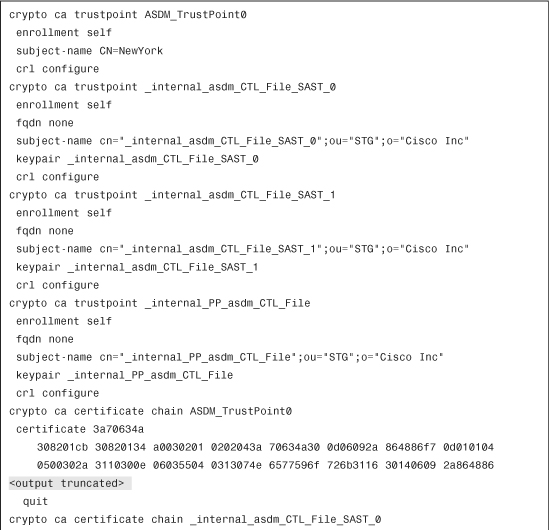
Example 7-15 shows the commands sent by ASDM to the Cisco ASA for the previous configuration example.
Example 7-15 Phone Proxy Commands Sent by ASDM
TLS Proxy
The TLS Proxy feature is used for decryption and inspection of Cisco Unified Communications encrypted signaling. This feature enables the Cisco ASA to intercept and decrypt encrypted signaling from Cisco-encrypted endpoints to the CUCM, while also applying the threat protection and access control. This feature is also often used to ensure confidentiality by re-encrypting the traffic onto the CUCM servers. TLS Proxy is never configured on its own; it is always used in conjunction with other features, such as Phone Proxy and Mobility Proxy.
Complete the following steps to configure the TLS Proxy feature, using ASDM:
Step 1. Log in to ASDM and navigate to Configuration > Firewall > Advanced > Encrypted Traffic Inspection > TLS Proxy.
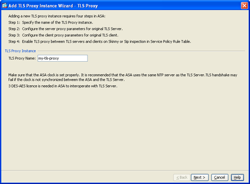
Step 2. Click on Add to add a new TLS Proxy instance. The TLS Proxy wizard screen is displayed.
Step 3. Enter a name for the TLS Proxy instance and click on Next. In this example, the name used is my-tls-proxy.
Step 4. Specify the server proxy certificate from the Server Proxy Certificate pull-down menu.
Step 5. Click Install TLS Server’s Certificate to install the TLS server certificate in Cisco ASA’s trust store. This is used to authenticate the TLS server during TLS handshake between the TLS proxy and the TLS server.
Step 6. Check the Enable Client Authentication During TLS Proxy Handshake check box so that the Cisco ASA sends a certificate and authenticates the TLS client during TLS handshake.
Step 7. Click Next.
Step 8. (Optional) Check the Specify the Proxy Certificate for the TLS Client check box to specify a client proxy certificate to use for the TLS Proxy.
Step 9. (Optional) Click the Specify the Internal Certificate Authority to Sign the Local Dynamic Certificate for Phones check box to specify an LDC Issuer to use for the TLS Proxy.
Step 10. In the Security Algorithms area, specify the available and active algorithms to be announced or matched during the TLS handshake (i.e., des-sha1, 3des-sha1, aes128-sha1, aes256-sha1, and null-sha1).
Step 11. Click Next.
Step 12. Click Finish.
Step 13. Click Apply to apply the configuration changes.
Step 14. Click Save to save the configuration in the Cisco ASA.
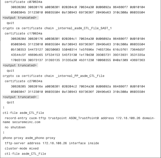
Example 7-16 shows the commands sent by ASDM to the Cisco ASA for the previous configuration example.
Example 7-16 TLS Proxy Commands Sent by ASDM
![]()
Mobility Proxy
The Mobility Proxy feature is designed to provide secure connectivity between Cisco Unified Mobility Advantage server and Cisco Unified Mobile Communicator clients. The Cisco ASA can act as a proxy, terminating and re-originating the TLS signaling between the CUMC and CUMA. Mobility Proxy is enabled for the Cisco UMA Mobile Multiplexing Protocol (MMP) by the MMP inspection feature on the Cisco ASA.
To enable MMP inspection via ASDM, navigate to Configuration > Firewall > Service Policy Rules > Edit Service Policy Rule and select MMP under the Edit Service Policy Rule dialog box. You can also configure several optional parameters for this MMP inspection by clicking on the Configure button. The Configure TLS Proxy dialog box is displayed. Select the TLS proxy name from the TLS Proxy Name pull-down menu. The previously configured TLS proxy (my-tls-proxy) is used in this example.
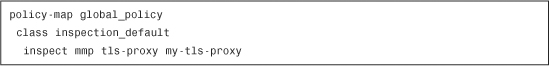
To configure FTP inspection via the CLI, use the inspect mmp command to enable FTP inspection. Example 7-17 shows the commands sent by ASDM to the Cisco ASA for the previous configuration example.
Example 7-17 MMP Inspection Commands Sent by ASDM
Presence Federation Proxy
The Presence Federation Proxy feature in the Cisco ASA provides secure connectivity between Cisco Unified Presence servers and Cisco or Microsoft Presence servers. The Cisco ASA terminates the TLS connectivity between these servers, and can inspect and apply policies for the SIP communications between the servers.
The configuration of the Presence Federation Proxy feature is the same as the TLS Proxy configuration.
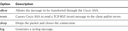
HTTP
The Cisco ASA HTTP inspection engine checks whether an HTTP transaction is compliant with RFC 2616 by checking the HTTP request message. The following are the predefined HTTP commands:
• OPTIONS
• GET
• HEAD
• POST
• PUT
• DELETE
• TRACE
• CONNECT
The Cisco ASA checks for these HTTP commands; if the message does not have any of these, the Cisco ASA verifies that it is an HTTP extension method/command (such as MOVE, COPY, EDIT). A syslog message is generated if both checks fail and the packet can be dropped. The Cisco ASA also has the capability to detect double-encoding attacks. This method, known as HTTP de-obfuscation, is one where an HTTP message is encoded by the normalization of encoded characters to ASCII-equivalent characters (sometimes also referred to as ASCII normalization). In a double-encoding attack, the attacker sends an encoded HTTP URI request that has been through two rounds of encoding. Traditionally, firewalls and intrusion detection devices detect the first round of encoding and normalize it. Therefore the attack still evades the firewall or IDS. The Cisco ASA HTTP inspection engine is able to detect double encoding and prevent this from happening.
The Cisco ASA also provides a feature to filter HTTP messages based on keywords. This is useful when looking for specific applications running over HTTP, such as online instant messenger (IM) applications, music sharing applications, and so on.
Enabling HTTP Inspection
To enable HTTP inspection via ASDM, navigate to Configuration > Firewall > Service Policy Rules > Edit Service Policy Rule and select HTTP under the Edit Service Policy Rule dialog box. You can also configure several optional parameters for this HTTP inspection by clicking on the Configure button. The Select HTTP Inspect Map dialog box is displayed. To create a HTTP inspect map for fine control over inspection, click on Add.
You can configure three different security levels (low, medium, or high). Low is the default. The following checks and actions are active when the security level is set to low:
• Protocol violation action: Drop connection
• URI filtering (if configured)
• Advanced inspections (if configured)
Note
Dropping of connections for unsafe methods and the dropping of connections for requests with non-ASCII headers are disabled when the security level is set to low.
The following checks and actions are active when the security level is set to medium:
• Protocol violation action: Drop connection
• Drop connections for unsafe methods: Allow only GET, HEAD, and POST
• URI filtering (if configured)
• Advanced inspections (if configured)
Note
Dropping of connections for requests with non-ASCII headers is disabled when the security level is set to medium.
The following checks and actions are active when the security level is set to high:
• Protocol violation action: Drop connection and log
• Drop connections for unsafe methods: Allow only GET and HEAD
• Drop connections for requests with non-ASCII headers
• URI filtering (if configured)
• Advanced inspections (if configured)
The URI Filtering button enables you configure the settings for an URI filter with the use of regular expressions.
If you are configuring the Cisco ASA via the CLI, use the inspect http command to enable HTTP inspection. You can also enable enhanced HTTP inspection by creating an HTTP map and associating it to the inspect http command. To create an HTTP map, use the http-map command, as shown in Example 7-18.
Example 7-18 HTTP Inspection Using an HTTP Map
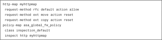
In Example 7-18, an HTTP map named myhttpmap is configured. Request method inspection is enabled to allow all default RFC-compliant methods. The two extension methods, move and copy, are not allowed. If these two extensions are detected, the HTTP connection is reset. The following HTTP extensions are supported by the Cisco ASA:
• copy
• edit
• getattribute
• getattributenames
• getproperties
• index
• lock
• mkdir
• move
• revadd
• revlabel
• revnum
• save
• setattribute
• startrev
• stoprev
• unedit
• unlock
Several enhanced HTTP inspection options can be configured under the http-map subcommands. When you configure an HTTP map, you are placed into the http-map prompt. The following subcommands are available to configure the necessary rules for enhanced HTTP inspection:
strict-http
The strict-http command changes the default action taken when noncompliant HTTP traffic is detected. The following is the subcommand syntax:
strict-http action {allow | reset | drop} [log]
Table 7-4 describes the strict-http command options.
Table 7-4 strict-http Command Options
The strict-http command is enabled by default. The default action is to log and send a TCP reset.
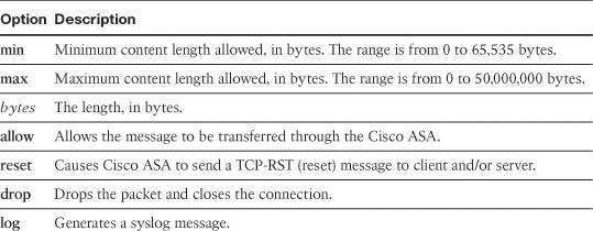
content-length
The content-length command limits the HTTP traffic allowed through the Cisco ASA, based on the content length of the HTTP message body. The following is the command syntax:
content-length {min bytes max bytes} action {allow | reset | drop} [log]
Table 7-5 describes the content-length command options.
Table 7-5 content-length Command Options
content-type-verification
When a web browser receives a document via HTTP, it must determine the document’s encoding (sometimes referred to as charset). The browser must know this to display non-ASCII characters correctly. The content-type-verification command limits the content types in HTTP messages transferred through the Cisco ASA. The Cisco ASA verifies that the header content-type value is in the internal list of supported content types. Additionally, it checks that the header content type matches the actual content in the data or entity body portion of the message. Here are the currently supported HTTP content types:
• Text/HTML
• Application/ Microsoft Word
• Application/octet-stream
• Application/x-zip
The following is the content-type-verification command syntax:
content-type-verification [match-req-rsp] action {allow | reset | drop} [log]
The match-req-rsp keyword enables the Cisco ASA to verify that the content-type field in the HTTP response matches the accept field in the corresponding HTTP request message.
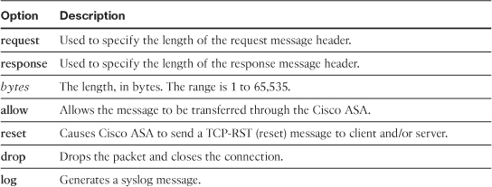
max-header-length
The max-header-length command limits the HTTP header length on traffic that passes through the Cisco ASA. Messages with a header length less than or equal to the configured value are allowed; otherwise, the configured action is taken. The following is the command syntax:
max-header-length {request bytes response bytes} action {allow | reset | drop} [log]
Table 7-6 describes the max-header-length command options.
Table 7-6 max-header-length Command Options
max-uri-length
The max-uri-length command limits the length of the Universal Resource Identifier (URI) in a request message. The command syntax is as follows:
max-uri-length bytes action {allow | reset | drop} [log]
Table 7-7 describes the max-uri-length command options.
Table 7-7 max-uri-length Command Options
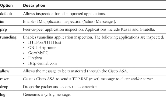
port-misuse
The port-misuse command restricts applications, such as instant messengers, that use HTTP as a transport protocol. The following is the command syntax:
port-misuse {default | im | p2p | tunneling} action {allow | reset | drop} [log]
Table 7-8 describes the port-misuse command options.
Table 7-8 port-misuse Command Options
Note
The port-misuse command is disabled by default.
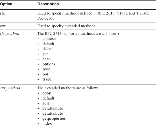
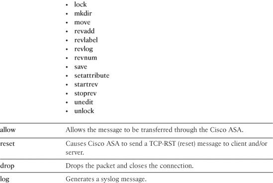
request-method
The request-method command configures a specific action for each of the supported HTTP request methods. The following is the command syntax:
![]()
Table 7-9 describes the request-method command options.
Table 7-9 request-method Command Options
Note
The request-method command is disabled by default.
transfer-encoding type
The transfer-encoding type command configures a specific action for each of the supported HTTP transfer-encoding types passing through the Cisco ASA. The following is the command syntax:
transfer-encoding type encoding_types action {allow | reset | drop} [log]
Table 7-10 describes the transfer-encoding type command options.
Table 7-10 transfer-encoding type Command Options
ICMP
Cisco ASA supports stateful inspection of Internet Control Message Protocol (ICMP) packets. To enable inspection of ICMP packets, use the inspect icmp command.
Additionally, Cisco ASA can translate ICMP error messages. It translates intermediate hops that send ICMP error messages based on the NAT configuration. Cisco ASA does this by overwriting the packet with the translated IP addresses.
Note
The traceroute command (which can be known as tracert on Microsoft Windows, trace or traceroute on Cisco IOS Software, or traceroute on UNIX) can be used to troubleshoot connectivity problems. The Cisco ASA blocks traceroute messages by default, and information about devices behind the Cisco ASA is not displayed in the output of the traceroute command. ICMP inspection is often used to allow traceroute messages.
Cisco ASA also has the capability to inspect ICMP error messages. ICMP error messages always contain the full IP header, including options, of the IP packet that failed and the first eight bytes of the IP data field. Cisco ASA makes sure that this information is present and that it is correct.
To enable ICMP inspection via ASDM, navigate to Configuration > Firewall > Service Policy Rules > Edit Service Policy Rule and select ICMP under the Edit Service Policy Rule dialog box. To enable ICMP error inspection via ASDM, navigate to the same location and select ICMP Error under the Edit Service Policy Rule dialog box.
To enable inspection of ICMP error messages via the CLI, use the inspect icmp error command. If this command is disabled, Cisco ASA does not translate any ICMP error messages generated by intermediate devices.
ILS
Cisco ASA supports inspection for the Internet Locator Service (ILS) protocol. ILS is based on the Lightweight Directory Access Protocol (LDAP) specification. Numerous applications use ILS for directory services, including the following:
• Microsoft NetMeeting
• Microsoft SiteServer
• Microsoft Active Directory
To enable ILS inspection via ASDM, navigate to Configuration > Firewall > Service Policy Rules > Edit Service Policy Rule and select ILS under the Edit Service Policy Rule dialog box.
To enable ILS inspection via the CLI, use the inspect ils command. This command is disabled by default.
The Cisco ASA ILS inspection engine provides support for the following:
• Decoding of the LDAP REQUEST/RESPONSE PDUs using the BER decode functions
• Parsing the LDAP packet
• Extracting the IP addresses
• Translating IP addresses as necessary (PAT is not supported)
• Encoding the PDU with translated addresses using BER encode functions
• Copying the newly encoded PDU back to the TCP packet
• Performing incremental TCP checksum and sequence number adjustment
Instant Messenger (IM)
The Cisco ASA supports IM inspection to protect against information leakage, propagation of worms, and other threats to the corporate network. Yahoo! and MSN Messenger protocols are supported.
To enable IM inspection via ASDM, navigate to Configuration > Firewall > Service Policy Rules > Edit Service Policy Rule and select IM under the Edit Service Policy Rule dialog box. You can also configure several optional parameters for this IM inspection by clicking on the Configure button. The Select IM Inspect Map dialog box is displayed. To create an IM inspect map for fine control over inspection, click on Add.
You can configure the match criterion and value for the IM inspect map within the Add IM Inspect dialog box shown in Figure 7-20.
Figure 7-20 Add IM Inspect Dialog Box
To specify that the IM inspect has only one match statement, select the Single Match button. The Match Type is used define whether traffic should match or not match the values. The Criterion pull-down menu enables you to configure the specific criterion of IM traffic to match. The following options are available:
• Protocol
• Service
• Source IP Address
• Destination IP Address
• Version
• Client Login Name
• Client Peer Login Name
• Filename
Note
You can allow or restrict the use of several IM services by using the Service criterion. The supported services include the following:
• Chat
• Conference
• File Transfer
• Games
• Voice Chat (not available for Yahoo! IM)
• Web Cam
You can select which IM protocols to match within the Protocol section. Yahoo! Messenger and MSN Messenger protocols are the two options.
You can also specify multiple matches for the IM inspection by selecting the Multiple Matches field. Click on Manage to add, edit, or delete IM Class Maps.
The Actions section enables you to configure the Cisco ASA to drop connection, reset, or enable logging when traffic matches the previously configured parameters.
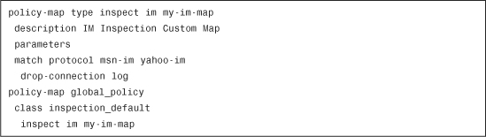
To enable IM inspection via the CLI, use the inspect im command. This command is disabled by default. Example 7-19 shows the command sent by ASDM to the Cisco ASA for the previously configured parameters.
Example 7-19 IM Inspection CLI Configuration
IPSec Pass-Through
The Cisco ASA supports IPSec pass-through, which is used to open pinholes for Encapsulating Security Payload (ESP) protocol traffic. When IPSec pass-through is enabled, all ESP data flows are allowed when a forward flow exists. There is no limit on the maximum number of connections that can be allowed. IPSec pass-through supports only the ESP protocol; it does not support the Authentication Header (AH) protocol. When IPSec pass-through is configured, ESP traffic does not need to be explicitly permitted by the use of ACLs; only Internet Key Exchange (IKE) traffic (UDP port 500) between the IPSec peers needs to be allowed.
To enable IPSec pass-through inspection via ASDM, navigate to Configuration > Firewall > Service Policy Rules > Edit Service Policy Rule and select IPSec Pass-Through under the Edit Service Policy Rule dialog box. You can also configure several optional parameters for this IPSec pass-through inspection by clicking on the Configure button. The Select IPSec Pass-Through Inspect Map dialog box is displayed. To create an IPSec pass-through inspect map for fine control over inspection, click on Add.
There are two different security levels (high and low). Low is the default and includes the following checks and actions:
• Maximum ESP flows per client: Unlimited.
• ESP idle timeout: 00:10:00.
• Maximum AH flows per client: Unlimited.
• AH idle timeout: 00:10:00.
When the security level is set to High the following checks and actions are enabled:
• Maximum ESP flows per client: 10.
• ESP idle timeout: 00:00:30.
• Maximum AH flows per client: 10.
• AH idle timeout: 00:00:30.
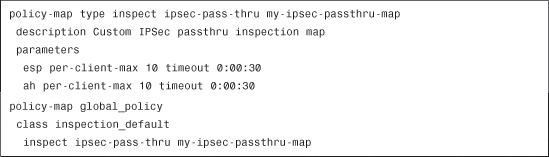
To enable IPSec pass-through inspection via the CLI, use the inspect ipsec-pass-thru command. Example 7-20 shows the CLI commands sent by ASDM when the security level is set to High.
Example 7-20 IPSec Pass-Through Inspection CLI Configuration
MGCP
The Media Gateway Control Protocol (MGCP) is the IETF standard for multimedia conferencing over IP. It offers a mechanism for controlling media gateways by providing conversion between the audio signals carried on telephone circuits and data packets carried over IP networks.
MGCP messages are ASCII based and are transmitted over UDP. This protocol is defined in RFC 3661. There are eight types of MGCP commands:
• CreateConnection
• ModifyConnection
• DeleteConnection
• NotificationRequest
• Notify
• AuditEndpoint
• AuditConnection
• RestartInProgress
Each command requires a reply. The first four commands are sent by the call agent to the gateway. The Notify command is sent by the gateway to the call agent. In some cases the gateway may also send a DeleteConnection command to tear down a connection to the call agent. The RestartInProgress command is used in the registration process of the MGCP gateway. The AuditEndpoint and the AuditConnection commands are sent by the call agent to the gateway.
The Cisco ASA performs the following tasks for MGCP inspection:
• Inspects all messages exchanged between the call agents and the media gateways
• Dynamically creates RTP and RTCP connections
• Supports and inspects retransmitted commands and responses
• Dynamically adapts to allow a command response to arrive from any of the call agents
A call agent is a device that provides call-processing functions, feature logic, and gateway control in an IP telephony system. An MGCP gateway handles the translation between audio signals and the IP packet network. In the MGCP configurations that Cisco IOS supports, the gateway can be a Cisco router, access server, or cable modem, and the call agent can be a server from Cisco (Cisco PGW or Cisco BTS Softswitches) or from a third-party vendor.
To enable MGCP inspection via ASDM, navigate to Configuration > Firewall > Service Policy Rules > Edit Service Policy Rule and select MGCP under the Edit Service Policy Rule dialog box. You can also configure several optional parameters for this MGCP inspection by clicking on the Configure button. The Select MGCP Inspect Map dialog box is displayed. To create an MGCP inspect map for fine control over inspection, click on Add.
The Command Queue tab enables you to configure the permitted queue size (1 to 2,147,483,647) for MGCP commands. The Gateways and Call Agents tab enables you to configure groups of gateways and call agents. Click on Add to add a new group of gateways and call agents for MGCP inspection. The Group ID identifies the ID of the call agent group. This group is used to associate one or more call agents with one or more MGCP media gateways. The Gateways field enables you to configure the IP address of the media gateway that is controlled by the associated call agent. The Call Agents field enables you to configure the IP address of a call agent that controls the MGCP media gateways in the call agent group.
To enable MGCP inspection via the CLI, use the inspect mgcp command. Create an MGCP map using the mgcp-map command to enable enhanced MGCP inspection. Example 7-21 demonstrates how to create an MGCP map for enhanced MGCP inspection.
Example 7-21 Enhanced MGCP Inspection
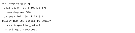
In Example 7-21, an MGCP map named mymgcpmap is configured. The call-agent command specifies a group of call agents that can manage one or more gateways. A call agent with IP address 10.10.10.133 and group ID 876 is configured.
Note
The group ID option can be any number between 0 and 2,147,483,647. Call agents with the same group ID belong to the same group. They may belong to more than one specific group.
The Cisco ASA can limit the maximum number of MGCP commands that will be queued waiting for a response to 500. The range of allowed values for the command-queue limit option is 1 to 2,147,483,647.
A gateway with IP address 192.168.11.23 in group 876 is also configured. This is used to specify which call agents are managing a particular gateway.
NetBIOS
NetBIOS was originally developed by IBM and Sytek as an API for client software to access LAN resources. NetBIOS has become the basis for many other networking applications. NetBIOS names are used to identify resources (e.g., workstations, servers, printers) on a network. Applications use these names to start and end sessions. NetBIOS names can consist of up to 16 alphanumeric characters. Clients advertise their names to the network. This is called the NetBIOS registration process and it is completed as follows:
Step 1. The client broadcasts itself and its NetBIOS information when it boots up.
Step 2. If there is another machine on the network that already has the broadcasted name, that NetBIOS client issues its own broadcast to advertise that the name is in use. Subsequently, the client that is trying to register stops all attempts to register that specific name.
Step 3. The client finishes the registration process if there is no other machine with the same name on the network.
Cisco ASA supports NetBIOS by performing NAT of the packets for NetBIOS Name Server (NBNS) UDP port 137 and NetBIOS Datagram Service (NBDS) UDP port 138.
To enable NetBIOS inspection via ASDM, navigate to Configuration > Firewall > Service Policy Rules > Edit Service Policy Rule and select NetBIOS under the Edit Service Policy Rule dialog box.
To enable NetBIOS inspection on the Cisco ASA, use the ip inspect netbios command.
PPTP
The Point-to-Point Tunneling Protocol (PPTP) is typically used for VPN solutions. (It is defined in RFC 2637.) Traditionally, the PPTP session negotiation is done over TCP port 1723 and the data traverses over the generic routing encapsulation (GRE) protocol (IP protocol 47). GRE does not have any Layer 4 port information. Consequently, it cannot be port address translated (PATed). PAT is performed for the modified version of GRE (RFC 2637) only when negotiated over the PPTP TCP control channel. PAT is not supported for the unmodified version of GRE (RFC 1701 and RFC 1702).
The Cisco ASA inspects PPTP protocol packets and dynamically creates the necessary GRE connections and translations to permit PPTP traffic. GRE traffic does not need to be explicitly permitted in the ASA when PPTP inspection is enabled.
Note
Cisco ASA supports only PPTP version 1.
To enable PPTP inspection via ASDM, navigate to Configuration > Firewall > Service Policy Rules > Edit Service Policy Rule and select PPTP under the Edit Service Policy Rule dialog box.
Use the inspect pptp command to enable PPTP inspection via the CLI.
Sun RPC
The Sun Remote Procedure Call (RPC) is a protocol used by the Network File System (NFS) and Network Information Service (NIS). NIS clients attempt to communicate with their administratively configured NIS server through RPC portmapper requests immediately after bootup. The RPC portmapper service converts RPC program numbers into TCP/UDP ports. The RPC server tells portmapper what port number it is listening to and what RPC program numbers it will use. The client first contacts portmapper on the server machine to determine the port number to which RPC packets should be sent. The default RPC portmapper port is 111.
Cisco ASA Sun RPC inspection provides the following:
• Bidirectional inspection of Sun RPC packets
• Support of Sun RPC over TCP and UDP
• Support of Portmapper v2 and RPCBind v3 and v4
• Support of DUMP procedure used by the client to query the server for all the supported services
• NAT and PAT support
To enable Sun RPC inspection via ASDM, navigate to Configuration > Firewall > Service Policy Rules > Edit Service Policy Rule and select SUNRPC under the Edit Service Policy Rule dialog box.
To enable Sun RPC inspection via the CLI, use the inspect sunrpc command. Use the Sun RPC services table to control Sun RPC traffic through the adaptive security appliance based on established Sun RPC sessions. To create entries in the Sun RPC services table, use the sunrpc-server command in global configuration mode.
RSH
Remote Shell (RSH) is a management protocol used by numerous UNIX systems. It uses TCP port 514. The client and server negotiate the TCP port number to be used by the client for the STDERR (standard error) output stream.
Cisco ASA supports NAT of the negotiated port number with RSH inspection.
To enable RSH inspection via ASDM, navigate to Configuration > Firewall > Service Policy Rules > Edit Service Policy Rule and select RSH under the Edit Service Policy Rule dialog box.
To enable this RSH inspection via the CLI, use the inspect rsh command.
RTSP
The Real-Time Streaming Protocol (RTSP) is a multimedia streaming protocol that many vendors use. Cisco ASA supports inspection for this protocol in compliance with RFC 2326. The following are some of the applications that use RTSP:
• RealAudio
• Apple QuickTime
• RealPlayer
• Cisco IP/TV
Most RTSP applications use TCP port 554. On some rare occasions, UDP is used in the control channel.
The commonly used TCP control channel negotiates the data channels used to transmit audio and video. This is negotiated based on the transport mode specified on the client.
The following are the supported Real Data Transport (RDT) protocol transports:
• rtp/avp
• rtp/avp/udp
• x-real-rdt
• x-real-rdt/udp
• x-pn-tng/udp
To enable RTSP inspection via ASDM, navigate to Configuration > Firewall > Service Policy Rules > Edit Service Policy Rule and select RTSP under the Edit Service Policy Rule dialog box.
Use the inspect rtsp command to enable RTSP inspection via the CLI.
SIP
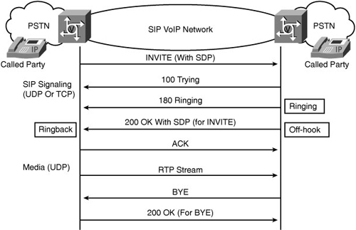
The Session Initiation Protocol (SIP) is a signaling protocol used in multimedia conferencing applications, IP telephony, instant messaging, and some event-notification features on several applications. This protocol is defined in RFC 3261. SIP signaling is sent over UDP or TCP port 5060. The media streams are dynamically allocated. Figure 7-21 illustrates the basics of an SIP call flow between two SIP calling entities and gateways, respectively.
The Cisco ASA is able to inspect any NAT SIP transactions successfully.
To enable SIP inspection via ASDM, navigate to Configuration > Firewall > Service Policy Rules > Edit Service Policy Rule and select SIP under the Edit Service Policy Rule dialog box.
To enable SIP inspection via the CLI, use the inspect sip command. You can see SIP connection statistics by using the show conn state sip command. The show service-policy command provides you with SIP inspection statistics.
SIP is also used by IM applications. The details on SIP extensions for instant messaging are defined in RFC 3428. Instant messengers use MESSAGE/INFO requests and 202 Accept responses when users chat with each other. The MESSAGE/INFO requests are sent after registration and subscription transactions are completed. For example, two users may have their IM application connected at any time, but not talk to each other for a long period of time. The Cisco ASA SIP inspection engine maintains this information for a set period of time according to the configured SIP timeout value.
To configure the idle timeout after which an SIP control connection will be closed, use the timeout sip command. The default timeout value is 30 minutes. Use the timeout sip_media command to configure the idle timeout after which an SIP media connection will be closed. The default is two minutes.
Example 7-22 shows how the Cisco ASA is configured with a SIP timeout of one hour.
Example 7-22 SIP Timeout Example
![]()
Note
The SIP media timeout value must be configured at least five minutes longer than the subscription duration (timeout sip).
Skinny (SCCP)
Skinny is a protocol used in VoIP applications. (Skinny is another name for the Simple Client Control Protocol [SCCP].) Cisco IP Phones, Cisco CallManager, and Cisco CallManager Express use this protocol. Figure 7-22 demonstrates the registration and communication process between a Cisco IP Phone and all the respective components such as Cisco CallManager.
Figure 7-22 Cisco IP Phone Registration and Communication Flow
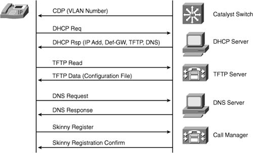
In Figure 7-22, the Cisco IP Phone is assigned to a specific VLAN. After that, it sends a request to the DHCP server to get an IP address, DNS server address, and TFTP server name or address. It also gets a default gateway address if you have set these options in the DHCP server.
Note
If a TFTP server name is not included in the DHCP reply, the Cisco IP Phone uses the default server name.
The Cisco IP Phone obtains its configuration from the TFTP server. It resolves the Cisco CallManager name via DNS and starts the Skinny registration process.
To enable Skinny inspection via ASDM, navigate to Configuration > Firewall > Service Policy Rules > Edit Service Policy Rule and select SCCP (Skinny) under the Edit Service Policy Rule dialog box.
To configure Skinny inspection via the CLI, use the inspect skinny command. This command is enabled by default.
Note
Cisco ASA does not support fragmented Skinny messages.
As previously discussed, Cisco IP phones download their configuration information from a TFTP server. This information includes the name or IP address of the Cisco CallManager server to which they need to connect. You must use an ACL to open UDP port 69 when the Cisco IP Phones are on a lower-security interface compared to the TFTP server. Enabling TFTP inspection with the inspect tftp command may be necessary to allow the secondary data connection initiated by the Cisco CallManager. If the Cisco IP Phones are on a lower-security interface compared to the Cisco CallManager, create a static NAT entry for the Cisco CallManager.
Note
Instructions on how to create ACLs and static NAT entries are covered in Chapter 4, “Controlling Network Access.”
SNMP
The Simple Network Management Protocol (SNMP) manages and monitors networking devices. Cisco ASA SNMP inspection enables packet traffic monitoring between network devices. The Cisco ASA can be configured to deny traffic based on the SNMP packet version. Early versions of SNMP are less secure. Denying SNMPv1 traffic may be required by your security policy. You do so by configuring an SNMP map with the snmp-map command and then associating it to the inspect snmp command via the CLI, as shown in Example 7-23.
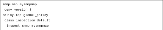
In Example 7-23, the Cisco ASA is set up for an SNMP map, called mysnmpmap, which denies any SNMPv1 packets. The following are the deny version subcommand options:
• 1 = SNMP version 1
• 2 = SNMP version 2 (party based)
• 2c = SNMP version 2c (community based)
• 3 = SNMP version 3
To enable SNMP inspection via ASDM, navigate to Configuration > Firewall > Service Policy Rules > Edit Service Policy Rule and select SNMP under the Edit Service Policy Rule dialog box. Click on Configure to configure the specific SNMP version(s) that are to be denied.
The Add SNMP Map dialog box is displayed, and it enables you to create a new SNMP map for controlling SNMP application inspection.
The following are the available SNMP version options:
• SNMP version 1
• SNMP version 2 (party based)
• SNMP version 2c (community based
• SNMP version 3
SQL*Net
Cisco ASA provides support for Oracle SQL*Net protocol inspection. It supports both versions 1 and 2. Cisco ASA is able to perform NAT and look in the packets for all embedded ports to allow the necessary communication for SQL*Net. SQL*Net inspection supports only the Transparent Network Substrate (TNS) Oracle SQL*Net format; it does not support the Tabular Data Stream (TDS) format.
To enable SQL*Net inspection via ASDM, navigate to Configuration > Firewall > Service Policy Rules > Edit Service Policy Rule and select SQLNET under the Edit Service Policy Rule dialog box.
To enable SQL*Net inspection via the CLI, use the inspect sqlnet command.
TFTP
The Trivial File Transfer Protocol (TFTP) allows systems to read and write files between them in a client/server relationship. One of the advantages of TFTP application inspection is that the Cisco ASA can prevent a host from opening invalid connections. Additionally, the Cisco ASA enforces the creation of a secondary channel initiated from the server. This restriction prevents the TFTP client from creating the secondary connection because the TFTP inspection uses ephemeral ports that cannot be guessed by an attacker.
To enable TFTP inspection via ASDM, navigate to Configuration > Firewall > Service Policy Rules > Edit Service Policy Rule and select TFTP under the Edit Service Policy Rule dialog box.
Use the inspect tftp command to enable TFTP inspection on the Cisco ASA via the CLI.
WAAS
The Cisco ASA supports application inspection for Wide Area Application Services (WAAS). When WAAS inspection is enabled, the Cisco ASA automatically detects WAAS connections and allows the optimized TCP traffic to enter the protected network.
To enable WAAS inspection via ASDM, navigate to Configuration > Firewall > Service Policy Rules > Edit Service Policy Rule and select WAAS under the Edit Service Policy Rule dialog box.
To enable WAAS application inspection via the CLI, use the inspect waas command.
XDMCP
The X Display Manager Control Protocol (XDMCP) is a protocol that many UNIX systems use to remotely execute and view applications.
Tip
Using XDMCP is inherently insecure; therefore, most of the UNIX distributions shipped have XDMCP turned off by default. Use XDMCP only in a trusted network.
XDMCP uses UDP port 177 to negotiate X sessions using a TCP port. The X manager communicates with the X server over TCP port 6000 + n (n = negotiated port).
To enable XDMCP inspection via ASDM, navigate to Configuration > Firewall > Service Policy Rules > Edit Service Policy Rule and select XDMCP under the Edit Service Policy Rule dialog box.
To enable XDMCP inspection via the CLI, use the inspect xdmcp command.
Summary
This chapter described how to use and configure application inspection on Cisco ASA. It demonstrated how the application inspection features ensure the secure use of applications and services. Details on the protocols that require special application inspection were covered in detail.