Chapter 4. Controlling Network Access
Cisco Adaptive Security Appliances (ASA) can act as a network firewall and can help protect one or more networks from intruders and attackers. You can control and monitor connections between these networks by using the robust features that Cisco ASA offers. You can ensure that all traffic from the protected networks to the unprotected networks (and vice versa) passes through the firewall based on the organization’s security policies. This chapter focuses on the features available for packet filtering, their implications, and their implementations.
Packet Filtering
The Cisco ASA can protect the inside network, the demilitarized zones (DMZs), and the outside network by inspecting all traffic that passes through it. You can specify policies and rules that identify what traffic should be permitted into or out of an interface. The security appliance uses an access control list to drop unwanted or unknown traffic when it attempts to enter the firewall. The access control list (ACL) is a collection of security rules or policies that allows or denies packets after looking at the packet headers and other attributes. Each permit or deny statement in the ACL is referred to as an access control entry (ACE). These ACEs can classify packets by inspecting Layer 2 through Layer 4 headers for a number of parameters, including the following:
• Layer 2 protocol information such as EtherTypes
• Layer 3 protocol information such as ICMP, TCP, or UDP
• Layer 3 header information such as source and destination IP addresses
• Layer 4 header information such as source and destination TCP or UDP ports
After an ACL has been properly configured, you can apply it to an interface to filter traffic. The security appliance can filter packets in both the inbound and outbound direction on an interface. When an inbound ACL is applied to an interface, the security appliance analyzes packets against the ACEs after receiving them. If a packet is permitted by the ACL, the firewall continues to process the packet and eventually passes the packet out the egress interface.
Note
The big difference between a router ACL and an appliance ACL is that only the first packet of a flow is subjected by an ACL in the security appliance. After that the connection is built, and subsequent packets matching that connection are not checked by the ACL.
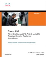
If a packet is denied by the ACL, the security appliance discards the packet and generates a syslog message indicating that such an event has occurred. In Figure 4-1, the security appliance administrator has applied to the outside interface an inbound ACL that permits only HTTP traffic destined for 209.165.202.131. All other traffic is dropped at the outside interface by the security appliance.
Figure 4-1 Inbound Packet Filtering
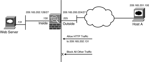
If an outbound ACL is applied on an interface, the security appliance processes the packets by sending them through the different processes (NAT, QoS, and VPN) and then applies the configured ACEs before transmitting the packets out on the wire. The security appliance transmits the packets only if they are allowed to go out by the outbound ACL on that interface. If the packets are denied by any one of the ACEs, the security appliance discards the packets and generates a syslog message indicating that such an event has occurred. In Figure 4-2, the security appliance administrator has applied to the inside interface an outbound ACL that permits only HTTP traffic destined for 209.165.202.131. All other traffic gets dropped at the interface by the security appliance.
Figure 4-2 Outbound Packet Filtering
Following are the some of the important characteristics of an ACL:
• When a new ACE is added to an existing ACL, it is appended to the end of the ACL.
• When a packet enters the security appliance, the ACEs are evaluated in sequential order. Hence, the order of an ACE is critical. For example, if you have an ACE that allows all IP traffic to pass through, and then you create another ACE to block all IP traffic, then the packets will never be evaluated against the second ACE because all packets will match the first ACE entry.
• There is an implicit deny at the end of all ACLs. If a packet is not matched against a configured ACE, then it is dropped and a syslog with message ID of 106023 is generated.
• By default, you do not need to define an ACE to permit traffic from a high security–level interface to a low security–level interface. However, if you want to restrict traffic flows from a high security–level interface to a low security–level interface, you can define an ACL. If you configure an ACL to a high security–level interface to a low security–level interface, it disables the implicit permit from that interface. All traffic is now subject to the entries defined in that ACL.
• An ACL must explicitly permit traffic traversing the security appliance from a lower to a higher security–level interface of the firewall. The ACL must be applied to the lower security–level interface.
• The ACLs (Extended or IPv6) must be applied to an interface to filter traffic that is passing through the security appliance.
• You can bind one extended and one Ethertype ACL in each direction of an interface at the same time.
• You can apply the same ACL to multiple interfaces. However, it is not considered to be a good security practice.
• You can use ACLs to control traffic through the security appliance as well as to control traffic to the security appliance. The ACLs controlling traffic to the appliance are applied differently than ACLs filtering traffic through the appliance, discussed in the “To-The-Box-Traffic Filtering” section.
• When TCP or UDP traffic flows through the security appliance, the return traffic is automatically allowed to pass through because they are considered established and bi-directional connections.
• Other protocols such as ICMP are considered unidirectional connections and thus you need to allow ACL entries in both directions. There is an exception for the ICMP traffic when you enable the ICMP inspection engine, discussed in Chapter 7 “Application Inspection.”
Types of ACLs
The security appliance supports five different types of ACLs to provide a flexible and scalable solution to filter unauthorized packets into the network:
Standard ACLs
Standard ACLs are used to identify packets based on their destination IP addresses. These ACLs can be used in scenarios such as split tunneling for the remote-access VPN tunnels (discussed in Chapter 17, “IPSec Remote Access VPNs”) and route redistribution within route maps (discussed in Chapter 5, “IP Routing”). These ACLs, however, cannot be applied to an interface for filtering traffic. A standard ACL can be used only if the security appliance is running in routed mode. In routed mode, the Cisco ASA routes packets from one subnet to another subnet by acting as an extra Layer 3 hop in the network.
Extended ACLs
Extended ACLs, the most commonly deployed ACLs, can classify packets based on the following attributes:
• Source and destination IP addresses
• Layer 3 protocols
• Source and/or destination TCP and UDP ports
• Destination ICMP type for ICMP packets
An extended ACL can be used for interface packet filtering, QoS packet classification, packet identification for NAT and VPN encryption, and a number of other features listed shortly in the “Comparing ACL Features” section. These ACLs can be set up on the security appliance in the routed and the transparent mode.
Note
Transparent Firewall mode is discussed in Chapter 9.
IPv6 ACLs
An IPv6 ACL functions similarly to an extended ACL. However, it identifies only IPv6 traffic passing through a security appliance.
EtherType ACLs
EtherType ACLs can be used to filter IP- and non-IP-based traffic by checking the Ethernet type code field in the Layer 2 header. IP-based traffic uses an Ethernet type code value of 0x800, whereas Novell IPX uses 0x8137 or 0x8138, depending on the Netware version.
An EtherType ACL can be configured only if the security appliance is running in transparent mode, as covered in Chapter 9, “Transparent Firewalls.”
Like all ACLs, the EtherType ACL has an implicit deny at the end of it. However, this implicit deny does not affect the IP traffic passing through the security appliance. As a result, you can apply both EtherType and extended ACLs to each direction of an interface. If you configure an explicit deny at the end of an EtherType ACL, it blocks IP traffic even if an extended ACL is defined to pass those packets.
Webtype ACLs
A Webtype ACL allows security appliance administrators to restrict traffic coming through the SSL VPN tunnels (discussed in Chapter 19). In cases where a Webtype ACL is defined but there is no match for a packet, the default behavior is to drop the packet because of implicit deny. On the other hand, if no ACL is defined, the security appliance allows traffic to pass through it.
Comparing ACL Features
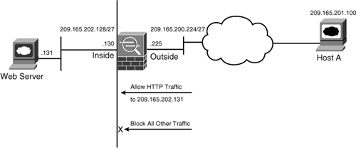
Table 4-1 compares the various types of ACLs, and specifies whether they can be used in conjunction with supported features on the security appliance.
Table 4-1 ASA Features and Types of ACLs
Configuring Traffic Filtering
Access-control lists on a security appliance can be used to not only filter out packets passing through the appliance but also to filter out packets destined to the appliance. This section discusses ways to set up the appliance for packet filtering.
• Thru-traffic filtering via CLI
• Thru-traffic filtering via ASDM
• To-the-box-traffic filtering
• IPv6 traffic filtering (optional)
Note
Throughout this chapter, we show you configuration examples through ASDM as well as the command-line interface (CLI).
Thru-Traffic Filtering via CLI
Thru-traffic filtering refers to traffic that is passing through the security appliances from one interface to another interface. The configuration to filter packets through the CLI in a security appliance is completed in two steps: Set up an ACL and apply that ACL to an interface.
Step 1: Set Up an ACL
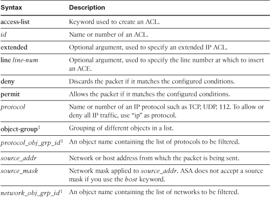
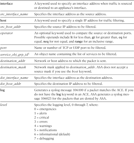
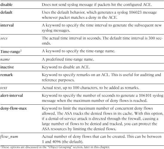
As mentioned earlier, an access-control list is a collection of access-control entries. When new connections try to pass through the security appliance, they are subjected to the ACL configured on the interfaces. The packets are either allowed or dropped based on the configured action on each ACE. An ACE can be as simple as permitting all IP traffic from one network to another, to as complicated as permitting or denying traffic originating from a unique source IP address on a particular port destined for a specific port on the destination address in a specific time period. You define an ACE by using the access-list command. You can define an extended ACL, an IPv6 ACL, or an EtherType ACL for filtering through the box traffic. The command syntax to define an extended ACE is as follows:
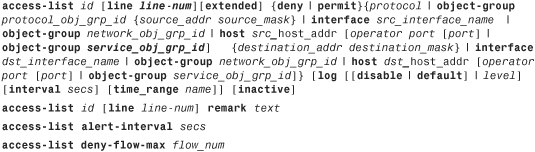
Table 4-2 lists and defines the arguments used in an ACE.
Table 4-2 ACE Syntax and Description
Note
The security appliance ignores the log option if an ACL is used with a feature other than interface traffic filtering.
The access-control list arguments may appear complicated at first but are fairly simple when you start implementing them in a lab or production environment. They not only give you full control over how you want to inspect traffic, but also provide you full logging capabilities in case you want to analyze traffic flow later. In Figure 4-3, SecureMe (the fictional company used in examples throughout this book) hosts a web server and an email server at its location in Chicago. One web server (209.165.202.131) allows traffic on port 80 (HTTP), whereas the email server (209.165.202.132) allows traffic on port 25 (SMTP). The security appliance allows only two client hosts—209.165.201.1 and 209.165.201.2—to initiate the traffic. All other traffic passing through the security appliance will be dropped and logged.
Figure 4-3 SecureMe Traffic Filtering
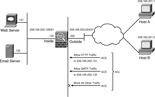
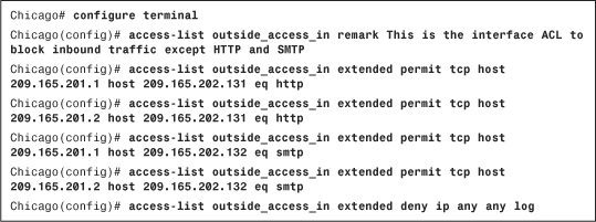
Example 4-1 shows the related configuration. An extended ACL called outside_access_in is set up with four ACEs. The first two ACEs allow HTTP traffic destined for 209.165.202.131 from the two client machines, whereas the last two ACEs allow SMTP access to 209.165.202.132 from both machines. Adding remarks to an ACL is recommended because it helps others to recognize its function. The system administrator has added This is the interface ACL to block inbound traffic except HTTP and SMTP as the remark on this ACL.
Example 4-1 Configuration of an Extended ACL
Chapter 3, “Initial Setup and System Maintenance,” discussed the concept of assigning security levels to an interface. As mentioned earlier in this chapter, the security appliance does not block the return TCP or UDP traffic on the lower-security interface if the traffic is originated from a host on the higher-security interface and vice-versa. For other connectionless protocols, such as GRE or ESP, you must permit the return traffic in the ACL applied on that interface. For the ICMP, you can either allow the return traffic in the ACL or enable ICMP inspection (discussed in Chapter 7, “Application Inspection”).
The security appliance software enables you to stop processing an ACE temporarily without removing the entry from the configuration. This is helpful if you are troubleshooting a connection issue through the security appliance and want to disable the entry. You do so by adding the inactive keyword at the end of the ACE.
Note
In version 8.0 or higher, you can rename an ACL by using the access-list <ACL-Name> rename command.
Step 2: Apply an ACL to an Interface
After configuring an ACL to identify traffic allowed or denied by the security appliance, the next step is to apply the ACL to an interface in either the inbound or the outbound direction. Apply the ACL by using the access-group command, followed by the name of the ACL, as shown in the following syntax:
access-group access-list {in | out} interface interface_name [per-user-override |
control-plane]
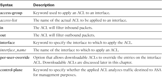
Table 4-3 lists and defines the arguments used in the access-group command.
Table 4-3 access-group Command Definition
In Example 4-2, an ACL called outside_access_in is applied to the outside interface in the inbound direction.
Example 4-2 Applying an ACL on the Outside Interface
![]()
Note
You can apply only one extended ACL in each direction of an interface. That means you can apply an inbound and an outbound extended ACL simultaneously on an interface.
Additionally, you can apply an extended and an IPv6 ACL in the same direction if the security appliance is set up to be in routed mode. In transparent mode, you can apply an extended and an etherType ACL in the same direction.
Thru-Traffic Filtering via ASDM
Now that you understand how ACLs are deployed in a security appliance via the CLI, setting it up via ASDM is even simpler. Simply log into ASDM as discussed in Chapter 3 and define an ACL and its associated ACEs by navigating to Configuration > Firewall > Access Rules, selecting the pull-down Add list and clicking Add Access Rule. ASDM opens up a new window where you can specify the following attributes:
• Interface—Select the name of the interface where you want to apply the access-control list. In a security appliance, traffic must be allowed from a low security–level interface to a high security–level interface and you can optionally filter traffic from high security–level interface to low security–level interface.
• Action—Select the action, either permit or deny, for the traffic matching this ACE. If you select permit, traffic is allowed to enter or exit an interface. If you choose deny, traffic is dropped by the security appliance.
• Source—Specify the source host IP, network, or object-group. The source information is any entity that originates traffic. For example, if a web client sends traffic to a web server, specify the IP address of the client as the source address.
• Destination—Specify the destination host IP, network, or object-group. The destination information is any entity that receives traffic. For example, if a web client sends traffic to a web server, specify the IP address of the server as the destination address.
• Service—Specify the destination service name such as TCP, UDP, SMTP, HTTP. For example, if a web client sends traffic to a web server, specify HTTP as the service. If you want all IP traffic to pass from specific source and destination addresses, specify IP as the service name. It can also be a protocol number such as 47 (for GRE) or 112 (for VRRP).
• Description—Specify a description, applied as a remark statement, for this access control entry. This optional argument is useful for auditing and reference purposes. You can specify up to 100 characters as the description of an access rule.
• Enable Logging—Specify whether you want the security appliance to generate a syslog message (106100) if a packet matches the ACE. If you do not have this option enabled, ASA generates a syslog message (106023) for packets that are denied by the firewall. If this option is enabled, you can specify a logging level, 0 through 7, where logging level 6 (informational) is the default. By default, permitted packets are not logged and if the logging argument is added, the security appliance generates a syslog only at the configured logging interval time and rate.
The following options are located under the More Options pull-down:
• Enable Rule—Select this option if you want the access rule to be operational. This is the default behavior and if you do not check this box, the access rule is inactive and does not process any traffic.
• Traffic Direction—Specify whether you want the firewall to apply the ACE in the inbound or outbound direction on the selected interface. When you define a new access rule, the default behavior is to inspect traffic in the inbound direction. If you would rather analyze traffic when it leaves a firewall interface, select Out as traffic direction.
• Source Service—Specify the source service name such as TCP, UDP, SMTP, or HTTP. If this option is not specified, then by default all source ports are allowed.
• Logging Interval—Specify the time interval, in seconds, after which the subsequent syslog messages are generated. The default time interval is 300 seconds. This option is grayed out until you select a logging level other than the default.
• Time Range—Specify a time-range name for this ACE. Time-based ACLs are discussed later in this chapter.
Tip
If you enter an address without the subnet mask, ASDM considers that to be a host address even if the address ends with a 0.
Note
ASDM defined an ACL name using InterfaceName_access_Direction as the standard format. For example, if you define an ACL to be applied to the outside interface in the inbound direction, then the ACL name is outside_access_in.
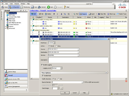
As shown earlier in Figure 4-3, SecureMe hosts a web server and an email server located at 209.165.202.131 and 209.165.202.132 respectively. However, only two client hosts—209.165.201.1 and 209.165.201.2—are allowed to initiate traffic. All other traffic initiated from the outside interface is dropped and logged. Figure 4-4 shows the related configuration where three ACE entries have already been configured. The administrator is adding the fourth ACE entry to allow the traffic from 209.165.201.2 to 209.165.202.131 on service TCP/SMTP. This rule is active and logging is enabled to generate syslog messages whenever there is a hit on the ACE. Traffic will be inspected in the inbound direction on the outside interface.
Figure 4-4 Defining an ACE on ASDM
Tip
For the well-known ports such as HTTP, SMTP, DNS, FTP, you do not need to specify TCP or UDP protocols in the service box. For example, if you want to specify SMTP as the service, you do not need to type tcp/smtp. You can simply type smtp in the service box.
To-The-Box-Traffic Filtering
To-the-box-traffic filtering, also known as management access rule, applies to traffic that terminates on the security appliances. This feature was introduced in version 8.0 of the code to filter traffic destined to the control plane of the security appliance. Some management-specific protocols such as SSH and Telnet have their own control list, where you can specify what hosts and networks are allowed to connect to the security appliance. However, they do not provide full protection from other types of traffic such as IPsec. Before you implement management access rules, consult these guidelines:
• Traffic filtering requires you to configure an ACL and then apply the ACL to the appropriate interface, using the control-plane keyword at the end.
• The ACL cannot be applied to an interface designated as a management-only interface.
• Management-specific protocols provide their own control-plane protection and have higher precedence than a to-the-box traffic filtering ACL. For example, if you allow a host to establish an SSH session (by defining its IP address in the ssh command) and then block its IP address in the management access rule, the host can establish an SSH session to the security appliance.
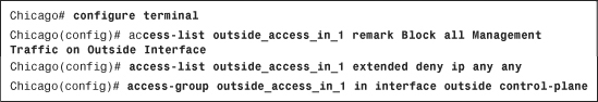
If you want to use the CLI to define a policy, use the control-plane keyword at the end of the access-group command. This declares that it is a management access rule to block traffic destined to the security appliance. In Example 4-3, a control-plane ACL called outside_access_in_1 is configured to block all IP traffic destined to the security appliance. This ACL is then applied to the outside interface in the inbound direction using the control-plane keywordcommand
Example 4-3 Defining a Management Access Rule Through CLI
Note
The management access rule can be applied only for incoming traffic. Therefore, the ACL can be applied only by using the in keyword of the access-group command.
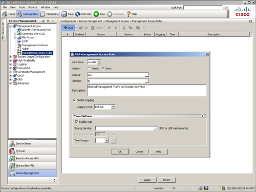
Want to set up an identical to-the-box traffic ACL through ASDM? Navigate to Configuration > Device Management > Management Access > Management Access Rules, click the pull-down Add list, and then select Add Management Access Rule. ASDM opens a new window where you can specify the following attributes:
• Interface—Select the interface where you want to allow or block the to-the-box traffic. You cannot select an interface already designated as the management-only interface.
• Action—Select the action, either permit or deny, for the traffic matching this rule.
• Source—Specify the source host IP, network, or object-group. The source is any entity that originates traffic destined to the interface of the security appliance.
• Service—Specify the destination service name, such as TCP, UDP, SMTP, or HTTP, that you want to allow or deny.
• Description—Specify a description of up to 100 characters that are useful for auditing and reference purposes.
• Enable Logging—Enable this option if you want the security appliance to generate a syslog message (106100) if a packet matches the control-plane ACE. You can include the appropriate logging level, discussed earlier in the chapter.
• Enable Rule—Select this option to make this ACE operational.
• Source Service—You can be more specific in defining the ACE by specifying the source service name (either TCP or UDP).
• Logging Interval—Specify the time interval to generate the subsequent new syslog messages in seconds.
• Time Range—Specify a time-range name for this ACE. Time-based ACLs are discussed later in this chapter.
As shown in Figure 4-5, a management access rule is defined to block all IP traffic that originates from the outside interface and is destined to the security appliance. A description of Block All Management Traffic on Outside Interface is added as a best practice.
Figure 4-5 Defining a Management Access Rule through ASDM
Note
Using ASDM, you can move an ACE up or down by selecting an ACE and then clicking the up or down arrow.
Set Up an IPv6 ACL (Optional)
If you use IPv6 traffic in your network, you can optionally configure an IPv6 ACL to control the traffic passing through the security appliance.
As discussed previously in the “Types of ACLs” section, the security appliance supports filtering IPv6 traffic that is passing through interfaces. You define an IPv6 ACL by using the ipv6 access-list command, followed by the name of the ACL. Like an extended ACL, the IPv6 ACL uses similar command options, as shown in the following syntax:
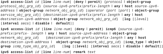
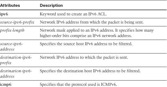
Table 4-4 defines the unique arguments of an IPv6 ACE that are different from the ones listed in Table 4-2.
Note
IPv6 ACLs are supported only in Cisco ASDM 6.2. If you use an earlier version of code, you must create IPv6 ACLs through the CLI.
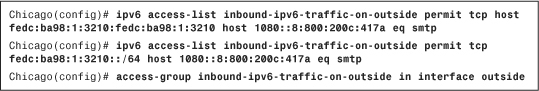
In Example 4-4, an ACL called inbound-ipv6-traffic-on-outside consists of two ACEs. The first ACE denies traffic from an IPv6 source fedc:ba98:1:3210:fedc:ba98:1:3210 if it is destined for a mail server (TCP port 25) located at 1080::8:800:200c:417a. The second ACE permits all mail traffic from the fedc:ba98:1:3210::/64 network if it is destined to 1080::8:800:200c:417a. The ACL is applied to the outside interface in the inbound direction.
Example 4-4 Configuring and Applying an IPv6 ACL on the Outside Interface
Advanced ACL Features
Cisco ASA provides many advanced packet-filtering features to suit any network environments. These features include
Object Grouping
Object grouping is a way to group similar items together to reduce the number of ACEs. Without object grouping, the configuration on the security appliance may contain thousands of lines of ACEs, which can become hard to manage. The security appliance follows the multiplication factor rule when ACEs are defined. For example, if three outside hosts need to access two internal servers running HTTP and SMTP services, the security appliance will have 12 host-based ACEs, calculated as follows:
Number of ACEs = (2 internal servers) × (3 outside hosts) × (2 services) = 12
If you use object grouping, you can reduce the number of ACEs to just a single entry. Object grouping can cluster network objects such as internal servers into one group and outside hosts into another. The security appliance can also combine both TCP services into a service object group. All these groups can be linked to each other in one ACE.
Note
Although the number of viewable ACEs is reduced when object groups are used, the actual number of ACEs is not. Use the show access-list command to display the expanded ACEs in the ACL.
The security appliance supports nesting an object group into another one. This hierarchical grouping can further reduce the number of configured ACEs in Cisco ASA.
Object Types
The security appliance supports four different types of objects that can group similar items or services. They include
• Protocol
• Network
• Service
Protocol
A protocol-based object group combines IP protocols (such as TCP, UDP, and ICMP) into one object. For example, if you want to group both TCP and UDP services of DNS, you can create an object group and add TCP and UDP protocols into that group.
Caution
When the protocol-based object group is used, all the protocols are expanded into different ACEs. It is therefore easy to permit unintended traffic if object groups are applied too liberally.
Network
A network-based object group specifies a list of IP host, subnet, or network addresses. Defining a network-based object group is very similar to defining a protocol-based object group.
Service
A service-based object group is used to cluster the TCP and/or UDP services together. By using the service-based object group, you can group TCP, UDP, or TCP and UDP ports into an object.
In versions 8.0 or higher, the security appliance enables you to create a service object group that can contain a mix of TCP services, UDP services, ICMP-type services, and any protocol such as ESP, GRE, and TCP, to name a few. This removes the need for a specific ICMP-type object group and a protocol object group. For example, you can create a service object group, called ProtocolServices, that can have HTTP, DNS, ICMP echo, and GRE protocols as its members.
ICMP-Type
The ICMP protocol uses unique types to send control messages, as documented in RFC 792. Using the ICMP-type object group, you can group the necessary types required to meet an organization’s security needs. For example, you can create an object group called echo to group echo and echo-reply. These two ICMP types are used when a user issues the ping command.
Tip
For more information about ICMP Type Numbers, visit http://www.iana.org/assignments/icmp-parameters.
Configuration of Object Types
If you prefer to use the CLI, you can configure object groups by using the object-group command followed by the object type. The complete command syntax is:
object-group {{protocol | network | icmp-type} grp_id | service grp_id {tcp | udp |
tcp-udp}}
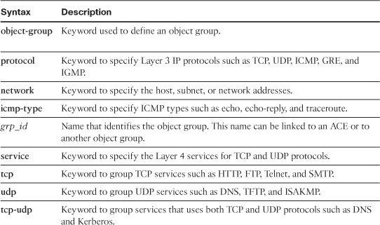
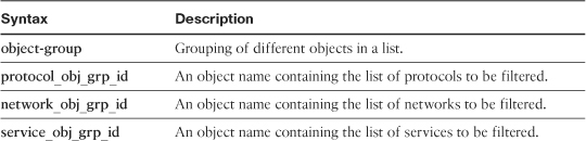
Table 4-5 lists and defines the arguments used in the object-group command.
Table 4-5 object-group Command Description
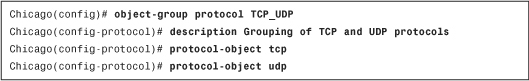
For example, if you want to set up a protocol-based object group, use the object-group protocol command followed by the name of the object group. As shown in Example 4-5, the protocol-object command is used to set up an object group called TCP_UDP to group the TCP and UDP protocols. The security appliance enables you to add a description under an object group. In this example, the description Grouping of TCP and UDP protocols identifies this group.
Example 4-5 Configuration of Protocol-Based Object Group
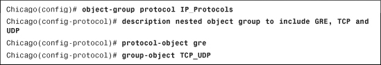
As mentioned earlier, an object group can be nested into another object group. You do so by using the group-object command. In Example 4-6, another protocol-based object group called IP_Protocols is set up to include GRE as the IP protocol. This object group also contains the TCP_UDP object group, defined in the preceding example. The description nested object group to include GRE, TCP and UDP is added to this group.
Example 4-6 Nesting of Protocol-Based Object Groups
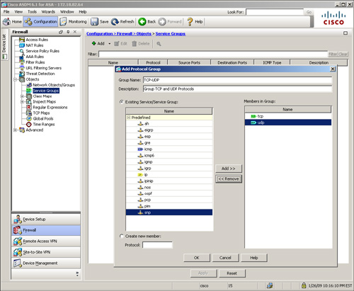
Defining an object group via ASDM is even simpler. Navigate to Configuration > Firewall > Objects > Service Groups > Add and select Protocol Group from the drop-down menu. ASDM opens a new window where you can specify a group name and an optional description. You can also select the desired protocol from an existing/predefined protocol list. You can even add a new IP protocol if it is not in the predefined protocol list. As illustrated in Figure 4-6, a new protocol-based object group called TCP-UDP is added with a description of Group TCP and UDP Protocols. From the Existing Service/Service Groups list, both TCP and UDP protocols are added to the Members in Group list. Click OK when you are finished.
Figure 4-6 Defining a Protocol-Based Object Group Through ASDM
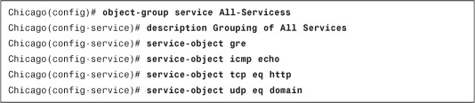
If you want to set up a services-based object group, use the object-group service command, followed by the name of the object group. As shown in Example 4-7, the service-object command is used to set up an object group called All-Services to group the HTTP, DNS, ICMP echo, and GRE protocols. The security appliance enables you to add a description under an object group. In this example, the description Grouping of All Services identifies this group.
Example 4-7 Configuration of Server-Based Object Group
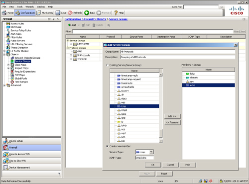
Want to define a service object group via ASDM? Navigate to Configuration > Firewall > Objects > Service Groups > Add and select Service Group from the drop-down menu. ASDM opens a new window where you can specify a service group name and an optional description. You can also select the desired protocols, TCP, UDP, and/or ICMP services from an existing/predefined protocol list. You can even add a new protocol or service if it is not in the predefined list. In Figure 4-7, a new service-based object group called All-Services is added with a description of Grouping of All Services. From the Existing Service/Service Groups list, select HTTP and move it to the Members in Group list. Similarly, select domain, GRE, and ICMP echo to the Members in Group list. Click OK when you are finished.
Figure 4-7 Defining a Service-Based Object Group Through ASDM
Object Grouping and ACLs
After object groups have been set up, you can use them in an ACL. The command syntax to define an ACE using object-group is
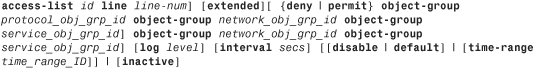
Table 4-6 defines the arguments used in an object group ACE that are different from the ones in Table 4-2.
Table 4-6 ACE Definition Using object-group
In Figure 4-8, the inside network has two servers, both running HTTP and SMTP services. If two hosts on the outside network try to access those servers, then eight ACEs should be configured to allow the hosts to communicate with each other. By using object group parameters in the ACE, you can reduce the viewable number of ACEs to one.
Figure 4-8 Inbound Packet Filtering Using Object Groups
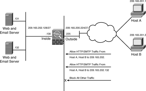
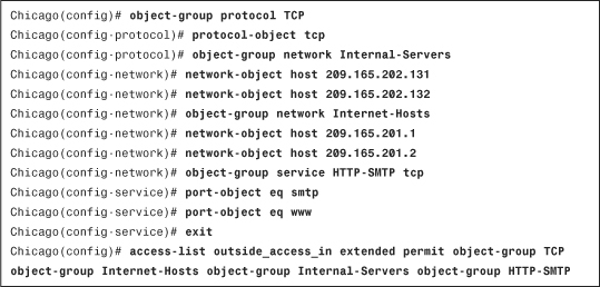
Example 4-8 shows the corresponding ACE using the object groups. A protocol-based object group called TCP is set up with the TCP protocol. The two network object groups configured are Internal-Servers and Internet-Hosts. The Internal-Servers object group specifies the IP addresses of the servers that are on the inside network, whereas Internet-Hosts is configured with the IP addresses of the hosts that are allowed to access the internal servers. A service-based object group called HTTP-SMTP is set up to group the HTTP and SMTP services. An ACL, named outside_access_in, is used to link all the configured object groups together.
Example 4-8 Configuration of an ACE Using Object Groups
After configuring the ACL, you can bind it to an interface for traffic filtering, as shown in Example 4-9. The ACL outside_access_in is applied to the outside interface in the inbound direction.
Example 4-9 Applying an ACL on the Outside Interface
![]()
Note
The security appliance enables you to use any mix of object group and non–object group parameters to set up an ACE. You can choose to use TCP as the protocol and an object group for source and destination IP addresses and subnet masks. An example of this is shown under the “Deployment Scenarios for Traffic Filtering” section later in this chapter.
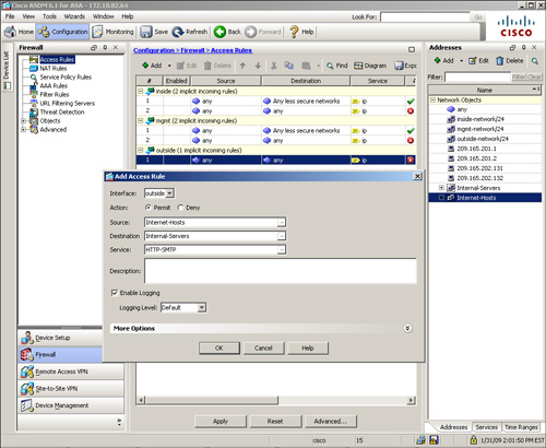
To define an ACL with object groups through ASDM, simply navigate to Configuration > Firewall > Access Rules, select the pull-down Add list and click Add Access Rule. ASDM opens a new window where you can select the preconfigured object groups in the source and destination services and addresses. As shown in Figure 4-9, an ACL is being configured for the outside interface that allows traffic from the Internet-Hosts object group to the Internal-Servers object group on the HTTP-SMTP service object group.
Figure 4-9 ACL Definition Using Object Groups
Standard ACLs
As mentioned earlier in this chapter, standard ACLs are used when the source network in the traffic is not important. These ACLs are used by processes, such as OSPF and VPN tunnels, to identify traffic based on the destination IP addresses.
You define standard ACLs by using the access-list command and the standard keyword after the ACL name. The command syntax to define a standard ACE is
access-list id standard [line line-num]{deny | permit} {any | host ip_address |
ip_address subnet_mask}
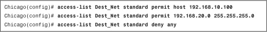
In Example 4-10, the security appliance identifies traffic destined for host 192.168.10.100 and network 192.168.20.0 and denies all other traffic explicitly. The ACL name is Dest-Net.
Example 4-10 Configuration of a Standard ACL
After a standard ACL is defined, it must be applied to a process for implementation. In Example 4-11, a route map called OSPFMAP is set up to use the standard ACL configured in the previous example. Route maps are discussed in Chapter 5, “IP Routing.”
Example 4-11 Route Map Using a Standard ACL
![]()
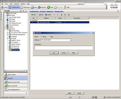
If you prefer to use ASDM to define a standard ACL, browse to Configuration > Firewall > Advanced > Standard ACL > Add > Add ACL. ASDM opens a new window where you can specify an ACL name. Click OK to add this ACL in the system. After the ACL is defined, you must add access-control entries (ACE). Click Add > Add ACE and specify the destination network that you want to permit or deny. In Figure 4-10, an ACL called Dest-Net is added with two ACEs. The first ACE permits traffic destined to 192.168.10.100, whereas the second ACE allows traffic destined to 192.168.20.0/24 network.
Figure 4-10 Standard ACL Definition
Time-Based ACLs
The security appliance can apply the ACLs based on the time interval to allow or deny network access. These rules, commonly referred as time-based ACLs, can prevent users from accessing the network services when the packets arrive outside the preconfigured time intervals. The ASA relies on the system’s clock when time-based ACLs are evaluated. Consequently, it is important to ensure that the system clock is accurate, and thus the use of Network Time Protocol (NTP) is highly recommended. You can use the time-based ACLs with the extended, IPv6, and Webtype ACLs.
Note
The time-based ACLs apply only to new connections and therefore the existing connections are not affected when the time-based ACLs become activate.
The security appliances enable you to specify two different types of time restrictions:
• Absolute—Using the absolute function, you can specify the values based on a start and/or an end time. This function is useful in cases where a company hires consultants for a period of time and wants to restrict access when they leave. In this case, you can set an absolute time and specify the start and the end time. After the time period expires, the consultants cannot pass traffic through the security appliance. The start and end times are optional. If no start time is provided, the security appliance assumes that the ACL needs to be applied right away. If no end time is configured, the security appliance applies the ACL indefinitely. Additionally, only one instance of the absolute parameter is allowed to be set up in a given time range.
• Periodic—Using the periodic function, you can specify the values based on the recurring events. The security appliance provides many easy-to-configure parameters to suit an environment. Time-based ACLs using this option are useful when an enterprise wants to allow user access during the normal business hours on the weekdays and wishes to deny access over the weekends. Cisco ASA enables you to configure multiple instances of the periodic parameter.
Note
The start and end times use the same format as the clock set command when configuring time and date values in the absolute function.
If both absolute and periodic parameters are configured in a time range, the absolute time parameters are evaluated first, before the periodic time value.
In periodic time ranges, you can configure a day-of-the-week such as Monday, specify the keyword weekdays for a work-week from Monday to Friday, or specify the keyword weekend for Saturday and Sunday. The security appliance can further the restrictions on the users by setting the optional 24-hour format hh:mm time specifications.
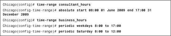
You can set up the time-based ACLs by using the time-range command, followed by the name of this entity. In Example 4-12, the administrator has created a time-range policy called consultant_hours for a new consultant whose start time/date is 8:00 a.m. on June 1, 2009, and end time/date is 5:00 p.m. on December 31, 2009. The administrator has created another time-range policy called business_hours for the regular employees who work from 8:00 a.m. to 5:00 p.m. on weekdays and from 8:00 a.m. to 12:00 p.m. on Saturdays.
Example 4-12 Time-Range Configuration
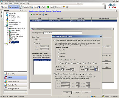
Using ASDM, configure time-range policies under Configuration > Firewall > Objects > Time Ranges > Add. ASDM opens a new window where you can specify a time-range policy name and define the absolute and/or periodic attributes. As shown in Figure 4-11, the administrator has defined a policy in ASDM similar to the policy in Example 4-12.
Figure 4-11 Definition of Time Range Policy in ASDM
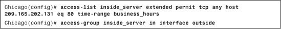
After a time-range entry has been set up, the next step is to link it to the ACL by using the time-range keyword, as illustrated in Example 4-13, in which the administrator allows outside users access to an internal web server, 209.165.202.131, during business hours (8:00 a.m. to 5:00 p.m. Monday through Friday, and 8:00 a.m. to 12:00 p.m. Saturday). If the outside users try to access the servers outside this time window, the security appliance drops the packets and generates a syslog message logging this event. The ACL name is inside_server and the time-range name is business_hours. The ACL is applied to the outside interface in the inbound direction.
Example 4-13 Configuration of a Time-Based ACL
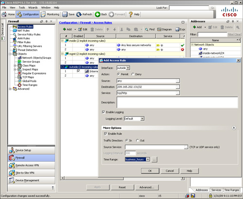
Using ASDM, you can link the time-range policy to an ACL by editing or adding a new access rule. In Figure 4-12, a previously defined time-range policy, business_hours, is linked to an access rule that allows any source to send HTTP traffic to an inside server located at 209.165.202.131.
Figure 4-12 Mapping a Time-Range Policy to an ACL in ASDM
Downloadable ACLs
The security appliance can dynamically download the ACLs from an external authentication server such as RADIUS or TACACS. This feature is discussed in Chapter 6, “Authentication, Authorization, and Accounting (AAA) Services.” When a user needs to access a service on the outside, the following sequence of events occurs, as illustrated in Figure 4-13:
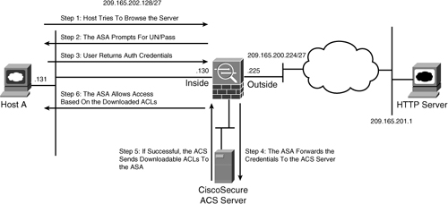
Step 1. User opens a browser application and tries to navigate to a web server located at 209.165.201.1. The packets are routed to Cisco ASA to reach the destination web server.
Step 2. Cisco ASA is set up for user authentication and thus prompts the user for authentication credentials.
Step 3. The user provides a username and password.
Step 4. The security appliance forwards the username and password to an authentication server.
Step 5. If authentication is successful, the server returns the ACLs to the security appliance.
Step 6. Cisco ASA applies the downloadable ACLs to the user.
ICMP Filtering
If you deploy interface ACLs to block all ICMP traffic, the security appliance, by default, does not restrict the ICMP traffic that is destined to its own interface. Depending on an organization’s security policy, an ICMP policy can be defined on the security appliance to block or restrict the ICMP traffic that terminates at a security appliance’s interface. The security appliances enable you to filter ICMP traffic to their interfaces by either deploying the control plane ACLs or defining the ICMP policy.
If you use the CLI, you can define an ICMP policy by using the icmp command, followed by an action (permit or deny), source network, ICMP type, and the interface where you want to apply this policy. As shown in Example 4-14, an ICMP policy is applied to the outside interface to block the ICMP echo packets sourced from any IP address. The second icmp statement permits all other ICMP types that are destined for the security appliance’s IP address.
Example 4-14 Defining an ICMP Policy
![]()
The ICMP commands are processed in sequential order, with an implicit deny at the end of the list. If an ICMP packet is not matched against a specific entry in the ICMP list, the packet is dropped. If there is no ICMP list defined, all ICMP packets are allowed to be terminated on the security appliance.
Prefer to use ASDM? Navigate to Configuration > Device Management > Management Access > ICMP > Add and specify an ICMP policy.
Content and URL Filtering
Traditionally, firewalls filter data packets by analyzing Layer 3 and/or Layer 4 header information. Cisco ASA can enhance this functionality by inspecting the content information in many Layer 7 protocols such as HTTP, HTTPS, and FTP. Based on an organization’s security policy, the security appliance can either pass or drop the packets if they contain content not allowed in the network. Cisco ASA supports two types of application layer filtering, namely content filtering and URL filtering.
Note
Cisco ASA also allows filtering and analyzing data traffic via application inspection, discussed in Chapter 7.
Content Filtering
Enabling Java or ActiveX in the production environment can cause naive users to download malicious executables that can cause loss of files and corruption in the user environment. A security network professional can disable Java and ActiveX processing in the browser, but this is not a very scalable solution. The other option is to use a network device such as Cisco ASA to remove the malicious content from the packets. Using the local content-filtering feature, the security appliance can inspect the HTTP header and filter out ActiveX and Java applets when the packets try to traverse from non-trusted hosts.
Cisco ASA can differentiate between friendly applets and untrusted applets. If a trusted website sends Java or ActiveX applets, the security appliance can forward them to the host requesting the connection. If the applets are sent from untrusted web servers, the security appliance can modify the content and remove the applets from the packets. This way, end users are not making decisions regarding which applet to accept or refuse. They can download any applets without being extra cautious.
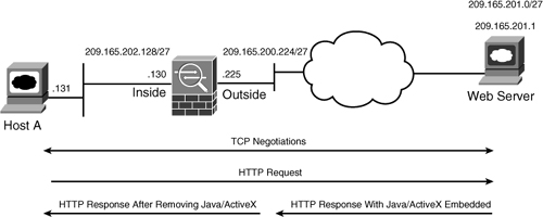
As shown in Figure 4-14, SecureMe wants to filter both ActiveX and Java from the data packets. After completing TCP negotiations, the web client sends an HTTP request to the web server. If Java/ActiveX is embedded in the packets, the security appliance removes them before sending them to the client.
Figure 4-14 ActiveX-Based Content Filtering
ActiveX Filtering
As mentioned in the preceding section, ActiveX can cause potential problems on the network devices if malicious ActiveX code is downloaded on the end-host devices. The <OBJECT ID> and </OBJECT> HTML tags are used to insert ActiveX code into the web page. The security appliance searches for these tags for traffic that originated on a preconfigured port. If the security appliance finds these tags, it replaces them with the comment tags <!— and —>. When the browser receives the HTTP packets with <!— and —>, it ignores the actual content by assuming that the content is the author’s comments.
Note
The security appliance cannot comment out the HTML tags if they are split across multiple network packets.
Java Filtering
For Java-based content filtering, the security appliance looks for <applet> and </applet> tags in the HTML data packets. Without Java filtering, the client browser tries to execute the code specified in <applet>, which begins with a 4-byte header, ca fe ba be. Therefore, to block Java applets, the security appliance searches for the <applet> and </applet> tags and replaces them with the comment tags, <!— and —>. Additionally, it blocks the applets if it sees the ca fe ba be string embedded in the packet.
Configuring Content Filtering
You set up local content filtering on the security appliance by using the filter command, followed by the content name to be removed. The following shows the complete command syntax:
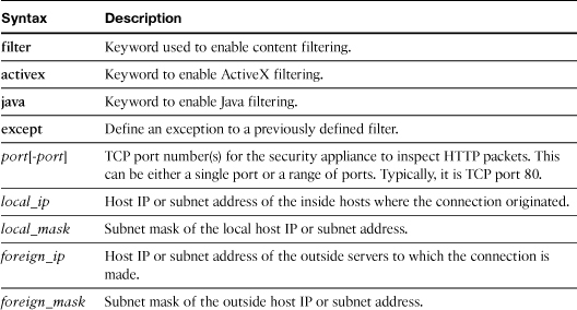
filter activex|java port[-port] except local_ip local_mask foreign_ip
foreign_mask
Table 4-7 describes the arguments used in the filter command.
Table 4-7 Syntax Description for filter java and filter activex Commands
In Example 4-15, the security administrator of an appliance in Chicago has set up a content-filtering policy to remove ActiveX objects from the HTTP packets (TCP port 80). The policy will be enforced if packets originate from the inside subnet 209.165.202.128/27 and destined for the external subnet 209.165.201.0/27. If traffic originates from or is destined for a different host, the security appliance will not filter ActiveX content.
Example 4-15 ActiveX Content Filtering
![]()
In Example 4-16, the security appliance is set up to filter Java applets from the TCP packets received on TCP port 8080. The Java applets are removed if packets originate from the inside subnet 209.165.202.128/27 and are destined for external subnet 209.165.201.0/27.
Example 4-16 Java Content Filtering
![]()
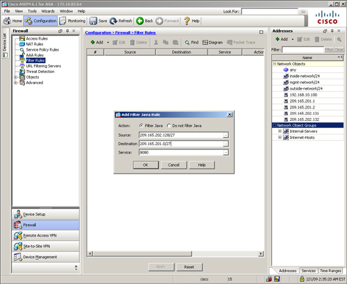
Define a filter for ActiveX and Java by navigating to Configuration > Firewall > Filter Rules > Add and selecting either Add Filter ActiveX Rule or Add Filter Java Rule. ASDM opens a new window where you can specify the attributes discussed in Table 4-7. Figure 4-15 shows that a filter is defined to remove Java applets from the packets if they are sourced from 209.165.202.128/27 and destined to 209.165.201.0/27 on TCP port 8080.
Figure 4-15 Defining Java-Based Content Filtering via ASDM
URL Filtering
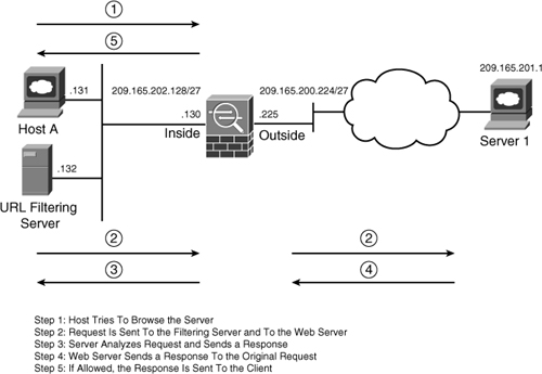
Traditionally, corporations monitor and control user Internet access by filtering questionable content. This prevents users from accessing sites that are deemed inappropriate based on the organization’s security policies. Additionally, employees do not waste network resources by sending traffic to the blocked Internet sites, which results in lower bandwidth usage and increased employee productivity. Cisco ASA can delegate packet-filtering responsibilities to an external server, such as Secure Computing SmartFilter (acquired by McAfee) or Websense. The URL-filtering process follows this sequence of events, shown in Figure 4-16.
Step 1. A web client (Host A) opens a browser application for Server 1.
Step 2. The security appliance forwards to the filtering server the URLs that the inside hosts try to reach. At the same time, the security appliance also forwards the original request to the external content server (Server 1).
Step 3. The filtering server analyzes the URLs and sends a permit or deny message back to the security appliance.
Step 4. The web server sends a reply destined for Host A.
Step 5. If the filtering server allows the connection, the security appliance forwards the response packet from the content server to the client. If the filtering server denies the connection, the security appliance drops the response packet from the content server and sends a message indicating a failed connection.
Both Websense and SmartFilter are external servers that can filter HTTP, HTTPS, and FTP requests from the client machines based on many attributes, including destination hostname, destination IP address, and URL. These servers can organize a list of Internet URLs into different categories and subcategorizes, including MP3, gambling, shopping, and adult content, for the ease of management.
Note
For more information about Websense and its features, visit http://www.websense.com.
Secure Computing was acquired by McAfee. Visit http://www.mcafee.com for more information.
Configuring URL Filtering
Configure URL filtering as follows:
Step 1. Define a filtering server.
Step 2. Configure HTTP, HTTPS, and FTP filtering.
Step 3. Buffer server responses (optional).
Step 4. Enable long URL support (optional).
Step 5. Cache server responses (optional).
These steps are described in more detail in the following sections.
Step 1: Defining a Filtering Server
You define an external filtering server by using the url-server command. The complete command syntax to specify a Websense server is
![]()
To define a SmartFilter server, the command syntax is
![]()
Note
Users may experience longer access times if the response from the filtering server is slow or delayed. This may happen if the filtering server is located at a remote location and the WAN link is slow.
Additionally, if the URL server cannot keep up with the number of requests being sent to it you may experience slow response times as well.
Table 4-8 lists and describes the arguments used in the url-server command.
Table 4-8 url-server Command Syntax and Description
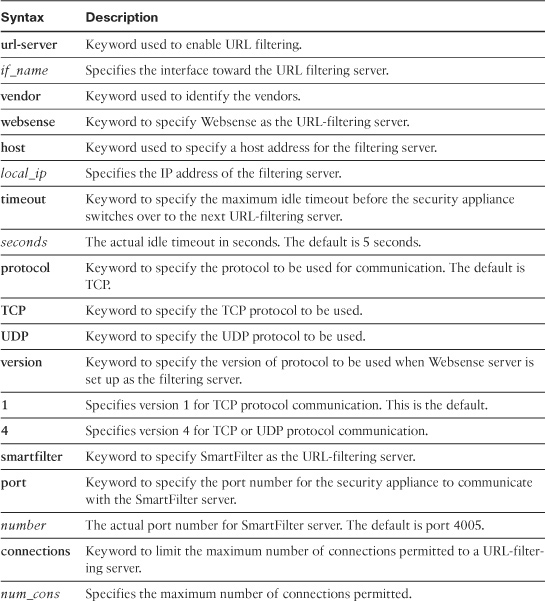
The url-server command does not verify whether a Websense or SmartFilter server is reachable from the security appliance. You can specify up to 16 filtering servers for redundancy. If the security appliance is not able to reach the first server in the list, it tries the second server from the list, and so on. Additionally, Cisco ASA does not allow for both SmartFilter and Websense servers to be defined at the same time. One must be deleted before the other is set up.
Note
If the security appliance is virtualized (as discussed in Chapter 8) you can define up to four filtering servers per context.
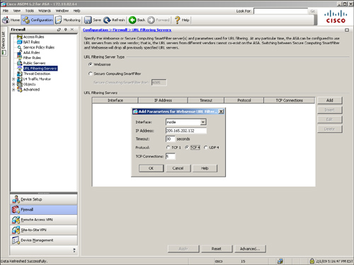
In Example 4-17, the administrator defines a Websense server located on the inside interface. The IP address of the server is 209.165.202.132, using TCP protocol version 4 with the default timeout value of 30 seconds.
Example 4-17 URL Filtering Using Websense
![]()
Note
The security appliance does not allow multiple SmartFilter URL servers to use different port numbers.
If you would rather use ASDM to define a URL server, follow Configuration > Firewall > URL Filtering Servers and select either the Websense or SmartFilter server. Click Add to specify the network parameters for the filtering server. Figure 4-17 illustrates a Websense server located at 209.165.202.132 and using TCP protocol version 4.
Figure 4-17 Defining a Websense Server Through ASDM
Step 2: Configuring HTTP, HTTPS, and FTP Filtering
After identifying the URL server, the security appliance can forward the HTTP, HTTPS, and FTP requests to the appropriate filtering servers. If the filtering server allows the connection, the security appliance forwards the response from the web and/or FTP server to the client host. If the filtering server denies the connection, the security appliance server drops the response and takes one of the following actions:
• It redirects the HTTP or HTTPS connection to a blocked page. The URL of the blocked page is returned by the filtering server.
• It returns a “code 550: Requested file is prohibited by URL filtering policy” error message to the FTP client.
The command syntax to enable HTTP filtering is
![]()
The command syntax to enable HTTPS filtering is
![]()
The command syntax to enable FT filtering is
![]()
Table 4-9 describes the arguments used in the filter command for URL filtering.
Table 4-9 filter Command Syntax and Description
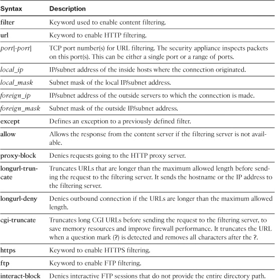
In case a URL-filtering server is not available, the security appliance drops the response from the content (HTTP or FTP) server. You can change this default behavior by specifying the allow keyword at the end of the filter command.
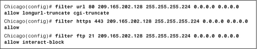
In Example 4-18, a security appliance is set up to filter HTTP, HTTPS, and FTP packets if the connections originate from 209.165.202.128/27 and are destined for any outside network (represented as 0.0.0.0 0.0.0.0). If the URL server is not available, the inside hosts are allowed to connect to the content servers. For the HTTP packets, the security appliance truncates CGI scripts and the long URLs. For the FTP connections, the security appliance restricts users from changing directories without specifying the complete directory path..
Example 4-18 Filtering of HTTP, HTTPS, and FTP Packet Content
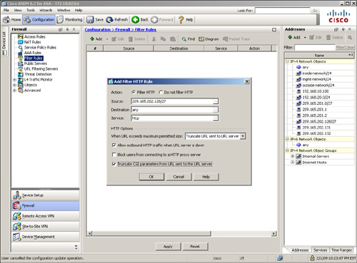
To define an HTTP, HTTPS, or FTP filter, go to Configuration > Firewall > Filter Rules > Add and select an appropriate filter rule (HTTP, HTTPS, or FTP) from the drop-down menu. In Figure 4-18, a HTTP filter rule is being added to check with the filtering server whether the connections originate from 209.165.202.128/27 and are destined for any outside network on port 80.
Figure 4-18 Defining an HTTP Filter Rule via ASDM
Step 3: Buffering Server Responses (Optional)
Using the URL-filtering feature, the security appliance sends a client’s request to the outside content (HTTP or FTP) server and simultaneously makes a URL lookup request to the filtering server. If the content server’s reply arrives prior to the URL-filtering server’s response, the security appliance drops the packet. You can change this default behavior by buffering the response packets from the content server until a reply is received from the filtering server. The command to enable packet buffering is url-block block followed by the number of blocks to be buffered. In Example 4-19, the security appliance is set up to buffer up to 128 1550-byte blocks in the HTTP response.
Example 4-19 Buffering of Server Responses
![]()
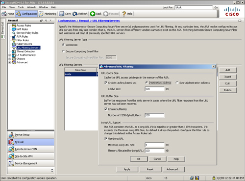
You can configure the security appliance to buffer response packets on the ASDM if you navigate to Configuration > Firewall > URL Filtering Servers > Advanced, select the Enable Buffering option, and specify a buffer size, as shown in Figure 4-19.
Figure 4-19 Buffering of Server Responses via ASDM
Step 4: Enabling Long URL Support (Optional)
The security appliance identifies a URL greater than 1159 bytes as a long URL. You can change this behavior if a Websense server is deployed for filtering purposes by using the url-block url-size command, followed by the size of the maximum long URL in kilobytes. In Example 4-20, the security appliance is set up to change the HTTP long URL size from 2 KB to 4 KB.
Example 4-20 Configuration to Enable Long URL Support
![]()
When the security appliance receives a URL longer than 1024 bytes, it breaks the URL into multiple IP packets and copies the TCP payload and the content of the URL into the buffer memory chunk. Each memory chunk is 1024 bytes, and the security appliance allocates another memory chunk for a URL longer than 1024 bytes for optimized memory management. Example 4-21 shows how to increase the allocated memory available for long URL support and packet buffering to 100 KB.
Example 4-21 Configuration to Increase the Memory for Long URL Support
![]()
To configure the security appliance to enable long URL support and increase the allocated memory for long URL buffer on the ASDM, navigate to Configuration > Firewall > URL Filtering Servers > Advanced and select Use Long URL, and specify the Maximum Long URL Size and Memory Allocated for Long URL, as previously shown in Figure 4-19.
Step 5: Caching Server Responses (Optional)
The security appliance can cache the responses from the filtering servers for a certain period of time, based on the destination and/or the source IP addresses. This way, when a user tries to access the same URL again, the security appliance does not forward the request to the filtering server but consults its local cache before allowing or denying the packets. This feature is currently supported by Websense filtering servers. Use the url-cache command to enable caching of server responses followed by the addressing policy. For destination address–based caching, use dst as the keyword in the url-cache command. If you prefer caching URL responses based on the source and destination addresses of a connection, use src_dst with the url-cache command. In Example 4-22, the security appliance allocates 128 KB of memory for destination-based URL caching.
![]()
To enable this feature within ASDM, navigate to Configuration > Firewall > URL Filtering Servers > Advanced, select the Enable caching based on option, and choose whether you want to enable destination-based or source/destination-based caching. Specify the memory you want to allocate for caching server responses. This was illustrated previously in Figure 4-19.
Deployment Scenarios for Traffic Filtering
Traffic filtering is the core functionality of any network or personal firewall. However, Cisco ASA integrates this core functionality with novel features to provide a scalable packet identification and filtering mechanism that can be used in almost any environment. Although ACLs can be deployed in many different ways, we examine two primary design scenarios to further your understanding of ACL deployment, namely using ACLs to filter inbound traffic and enabling content filtering using Websense.
Note
These design scenarios are discussed here to reinforce learning and thus should be used for reference only.
Using ACLs to Filter Inbound Traffic
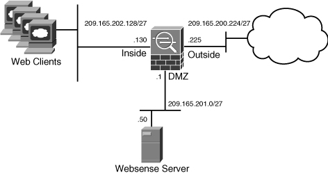
In this first scenario, SecureMe hosts three web servers, two email servers, and a DNS server at its Chicago office. All these servers are located on the DMZ network 209.165.201.0/27, as shown in Figure 4-20.
Figure 4-20 SecureMe ASA in Chicago, Using ACLs
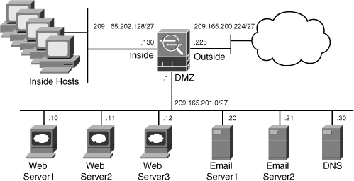
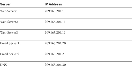
Table 4-10 lists all the servers and their corresponding IP addresses.
Table 4-10 Server Address Assignments
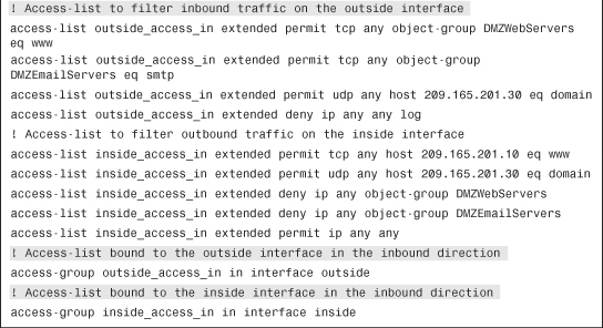
SecureMe wants to provide Internet connectivity for all inside trusted users. However, inside hosts are allowed to access only Web Server1 and DNS server on the DMZ network. Internet users can access all servers in the DMZ network on their respective TCP and UDP ports, but they should not be able to send any traffic to the inside network. All traffic dropped by the access lists should be logged.
To achieve these requirements, the administrator has configured two object groups: DMZWebServers to group all the HTTP servers and DMZEmailServers to group both email servers. Both network groups are bound to the ACL to allow DNS, HTTP, and SMTP traffic only. All other traffic gets denied and logged by the security appliance. This ACL is applied on the outside interface in the inbound direction.
To limit the inside traffic to the DMZ network, the administrator has configured an access rule to allow the trusted hosts on the inside network to access Web Server1 and DNS. The ACL is applied to the inside interface in the inbound direction.
Configuration Steps with ASDM
The configuration for ASDM as outlined here assumes that you have IP connectivity from the ASDM client to the management IP address (172.18.82.64) of the security appliance.
Step 1. Navigate to Configuration > Firewall > Objects > Network Objects/Groups, click Add > Network Object Groups and specify DMZWebServers as the Group Name. Choose Create New Network Object Member, specify 209.165.201.10 under IP address with a Netmask of 255.255.255.255, and click Add>>. Similarly, add 209.165.201.11 and 209.165.201.12 as object group members. Click OK to create the object group.
Step 2. Navigate to Configuration > Firewall > Objects > Network Objects/Groups, click Add > Network Object Groups, and specify DMZEmailServers as the Group Name Choose Create New Network Object Member, specify 209.165.201.20 under IP address with a Netmask of 255.255.255.255, and click Add>>. Similarly, add 209.165.201.21 as an object group member. Click OK to create the object group.
Step 3. Navigate to Configuration > Firewall > Access Rules > Add > Add Access Rules and specify the following attributes:
• Interface: outside
• Action: Permit
• Source: any
• Destination: DMZWebServers
• Service: tcp/http. Click OK when you are finished.
Step 4. Navigate to Configuration > Firewall > Access Rules > Add > Add Access Rules and specify the following attributes:
• Interface: outside
• Action: Permit
• Source: any
• Destination: DMZEmailServers
• Service: tcp/smtp. Click OK when you are finished.
Step 5. Navigate to Configuration > Firewall > Access Rules > Add > Add Access Rules and specify the following attributes:
• Interface: outside
• Action: Permit
• Source: any
• Destination: 209.165.201.30/32
• Service: udp/domain. Click OK when you are finished.
Step 6. Navigate to Configuration > Firewall > Access Rules > Add > Add Access Rules and specify the following attributes:
• Interface: outside
• Action: Deny
• Source: any
• Destination: any
• Enable Logging: Checked. Click OK when you are finished.
Step 7. Navigate to Configuration > Firewall > Access Rules > Add > Add Access Rules and specify the following attributes:
• Interface: inside
• Action: Permit
• Source: any
• Destination: 209.165.201.10/32
• Service: tcp/http. Click OK when you are finished.
Step 8. Navigate to Configuration > Firewall > Access Rules > Add > Add Access Rules and specify the following attributes:
• Interface: inside
• Action: Permit
• Source: any
• Destination: 209.165.201.30/32
• Service: udp/domain. Click OK when you are finished.
Step 9. Navigate to Configuration > Firewall > Access Rules > Add > Add Access Rules and specify the following attributes:
• Interface: inside
• Action: Deny
• Source: any
• Destination: DMZWebServers
• Service: ip. Click OK when you are finished.
Step 10. Navigate to Configuration > Firewall > Access Rules > Add > Add Access Rules and specify the following attributes:
• Interface: inside
• Action: Deny
• Source: any
• Destination: DMZEmailServers
• Service: ip. Click OK when you are finished.
Step 11. Navigate to Configuration > Firewall > Access Rules > Add > Add Access Rules and specify the following attributes:
• Interface: inside
• Action: Permit
• Source: any
• Destination: any
• Service: IP. Click OK when you are finished.
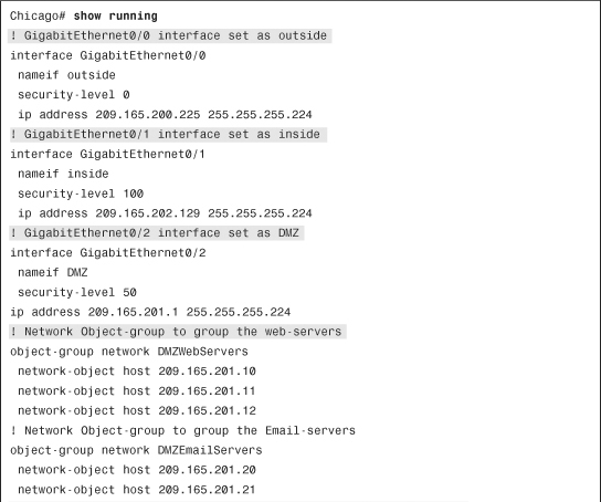
Configuration Steps with CLI
Example 4-23 shows the relevant configuration of the ASA in Chicago. Some configuration output has been removed for brevity.
Example 4-23 ASA’s Full Configuration Using Inbound and Outbound ACLs
Using Websense to Enable Content Filtering
In this scenario, SecureMe wants to enable content filtering for its users to ensure that they do not access certain questionable URLs such as pornographic and gaming sites. The administrator has set up a Websense server to filter out the URLs if the packets are destined for these Internet sites, using the HTTP, HTTPS, or FTP protocols. The administrator does not want to overload the filtering server by sending the duplicate request for the same source and destination addresses. SecureMe’s policy allows users to go through the security appliance if the filtering server is unavailable. Additionally, if the reply from the content server arrives before the response is received from the filtering server, SecureMe wants the security appliance to buffer the reply rather than drop it.
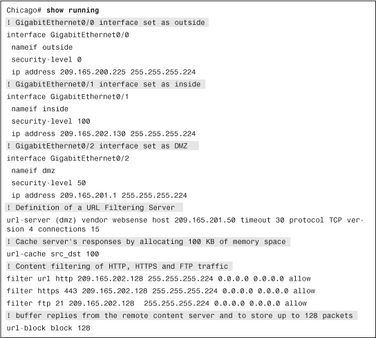
To meet the company’s goals, the administrator has specified a Websense server as a URL-filtering device in the network that is located on the DMZ interface at 209.165.201.50, as illustrated in Figure 4-21. To avoid overloading the filtering server, the maximum simultaneous limit is set to 15, and the server’s responses are cached because 100 KB of memory space has been allocated. The security appliance is set up to buffer replies from the remote content servers if they are received before the websense reply. It is set up to store up to 128 packets.
Figure 4-21 SecureMe Network Using Content Filtering
Configuration Steps with ASDM
The ASDM configuration steps as outlined here assume that you have IP connectivity from the ASDM client to the management IP address (172.18.82.64) of the security appliance.
Step 1. Navigate to Configuration > Firewall > URL Filtering Servers and select Websense. Under URL Filtering Servers, click Add and specify the following attributes:
• Interface: DMZ
• Protocol: TCP 4
• Connections: 15
Step 2. Navigate to Configuration > Firewall > URL Filtering Servers > Advanced and specify the following attributes:
• Enable caching based on: Source/destination address
• Cache Size: 100
• Enable Buffering: Checked
• Number of 1550-Byte Buffers: 128
Step 3. Navigate to Configuration > Firewall > Filter Rules > Add > Add HTTP Filter Rule and specify the following attributes:
• Action: Filter HTTP
• Source: 209.165.202.128/27
• Destination: any
• Service: http
• Allow outbound HTTP traffic when URL server is down: Checked
Step 4. Navigate to Configuration > Firewall > Filter Rules > Add > Add HTTPS Filter Rule and specify the following attributes:
• Action: Filter HTTPS
• Source: 209.165.202.128/27
• Destination: any
• Allow outbound HTTPS traffic when URL server is down: Checked
Step 5. Navigate to Configuration > Firewall > Filter Rules > Add > Add FTP Filter Rule and specify the following attributes:
• Action: Filter FTP
• Source: 209.165.202.128/27
• Destination: any
• Service: ftp
• Allow outbound FTP traffic when URL server is down: Checked
Example 4-24 shows the complete configuration for Cisco ASA used in this deployment. Some configuration output is removed for brevity.
Example 4-24 ASA’s Full Configuration Using a URL-Filtering Server
Monitoring Network Access Control
The show commands provided by Cisco ASA are extremely useful both in checking the health and status of the hardware and in isolating network-related issues. The necessary show commands to manage network access control are discussed in the following two sections.
Monitoring ACLs
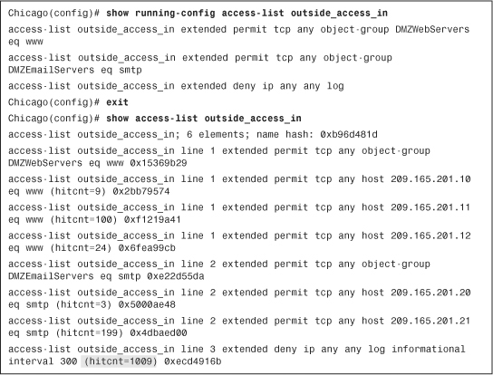
Cisco ASA provides the show access-list command to determine whether the packets are passing through the configured ACLs. When a packet is matched against an ACE, the security appliance increments the hitcnt (hit count) counter by one. This is useful if you want to know what ACEs are heavily used in your network.. Example 4-25 shows the output of an ACL called outside_access_in. If object groups are used and the show access-list outside_access_in command is executed, Cisco ASA expands and displays all the ACEs that are otherwise grouped into protocols, networks, and services. As shown in this example, the security appliance processed 1009 packets in the sixth ACE where the packets were denied and logged by the ACE.
Example 4-25 Output of show access-list outside_access_in
Tip
The security appliance assigns a unique hash to each:
• ACL such as 0xb96d481d is assigned to ACL outside_access_in.
• Object-group ACE such as 0x15369b29 is assigned to the DMZWebServers entry.
• Expanded object-group entry such as 0x2bb79574 is assigned to the ACE used for 209.165.201.10.
If you are interested to see hit counts for a specific ACE entry and you know its associated hash, you can use the show access-list | include followed by the hash number.
To reset the hit-count counters, you can issue the clear access-list <ACL_name> counters command, as shown in Example 4-26, in which the counters for the outside_access_in ACL are being cleared.
Example 4-27 Resetting Hit-Count Counters with clear access-list counters
![]()
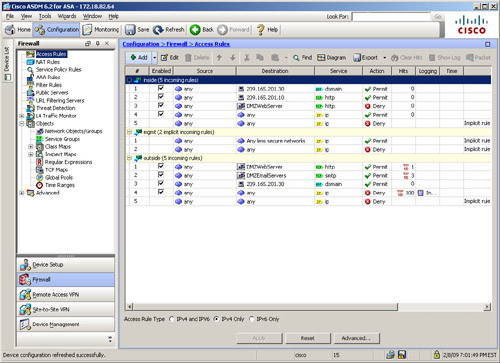
If you are using ASDM, you can monitor the ACL usage by going to Configuration > Firewall > Access Rules and monitoring the Hits column next to each ACL entry. Unlike the show access-list command, where it expands each ACL entry, the hit count information via ASDM shows only packets matching the ACL entries with object-groups as shown in Figure 4-22. ASDM also shows the top 10 ACL entries of an access control list. Want to reset the ACL hit counts? Click the Clear Hits option.
Figure 4-22 Viewing ACL Hit Counts via ASDM
If a UDP, TCP, or ICMP packet is allowed to pass through the security appliance, a connection entry is created, which can be shown by using the show conn command, as displayed in Example 4-27.
Example 4-27 Output of show conn
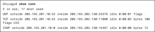
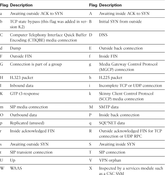
The first column of the connection entry displays the protocol used, followed by outside and an IP address to indicate the IP address of the outside host and then inside and an IP address to display the inside hosts’ IP addresses. It also shows the source and destination Layer 4 ports. The security appliance shows the idle timer per connection in hours, minutes, and seconds. The most important information to look at is the flags counter, which has the information about the current state of the connection. Table 4-11 lists and describes all the flags. The highlighted TCP entry, in Example 4-28, has flags set to UIO to indicate that the connection is up and is passing traffic in both inbound and outbound directions.
Table 4-11 Description of Flags in the show conn Command Output
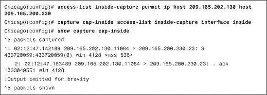
Cisco ASA can act as a sniffer to gather information about the packets passing through the interfaces. This is important if you want to confirm that traffic from a particular host or network is reaching the interfaces. You can use an ACL to identify the type of traffic and bind it to an interface by using the capture command.
In Example 4-28, an ACL, called inside-capture, is set up to identify packets sourced from 209.165.202.130 and destined for 209.165.200.230. The security appliance is using this ACL to capture the identified traffic on the inside interface, using a capture list named cap-inside.
To view the captured packets, use the show capture command followed by the name of the capture list. In Example 4-28, the security appliance captured 15 packets that matched the ACL on the inside interface. The highlighted entry shows that it is a TCP SYN (shown as “S” after the destination port) packet sourced from 209.165.202.130 with a source port of 11084 and it is destined for 209.165.200.230 on destination port 23. The TCP window size is 4128, whereas the Maximum Segment Size (MSS) is set to 536 bytes.
Note
When the capture command is enabled, the security appliance allocates memory right away. The default memory allocation is 512 KB. The security appliance can overwrite content when the allocated memory is full by removing the oldest entry first. The capture command has minimal CPU impact and therefore it is one of the most important troubleshooting tools available in Cisco ASA.
The output of the capture command can be exported into pcap format, which can be imported into a sniffing tool such as Wireshark or TCPDUMP for further analysis. To download the file in pcap format, use https://<IPAddressOfASA>/capture/<CaptureName>/pcap in a browser. For example, to download the pcap file for the capture defined in Example 4-28, use https://172.18.82.64/capture/cap-inside/pcap.
Tip
If you want to see traffic in real time, you can use the real-time keyword in the capture. For example, the capture command in Example 4-29 can be defined for real-time traffic analysis as capture out-inside access-list inside-capture interface inside real-time. Even though real-time capturing is extremely useful in troubleshooting traffic-related issues, the security appliance displays up to only 1000 packets in case of excessive traffic load.
Example 4-29 Output of show asp drop
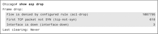
If the security appliance is dropping packets but you are not sure of the reason, look at the asp (accelerated security path) drop counter by issuing the show asp drop command, as shown in Example 4-29.
You can see that the security appliance has dropped over a million packets because they were denied by the ACLs. Over 600 packets were dropped because the adaptive security appliance received a non-SYN packet as the first packet of a connection. This usually occurs when the client and server believe that a connection was opened but the firewall has already closed that session. Finally, the security appliance dropped three packets when the interface’s link was down.
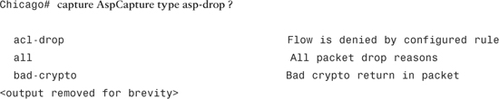
Note
The security appliance allows you to capture on a specific drop type or on all ASP drop types through the capture command, as follows:
Monitoring Content Filtering
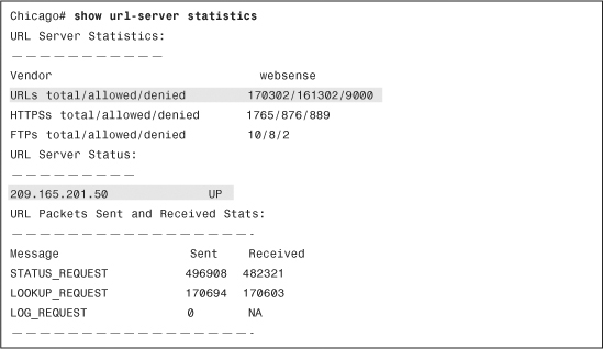
If the security appliance is set up to filter traffic by inspecting URLs, you can view the packet-filtering statistics to ensure that any non-allowed traffic is denied. Use the show url-server statistics command to check how many packets have been allowed and dropped based on the responses from the URL server (such as Websense). In Example 4-30, the security appliance has denied 9000 URL (HTTP) attempts because of restricted or blocked content, whereas it has allowed 161,302 requests. The status of the Websense server is up, which indicates that there is a bidirectional communication channel between the server and the security appliance.
Example 4-30 Output of show url-server statistics
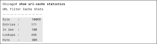
If URL caching is enabled, as in the case of the deployment scenario, you can collect statistics such as allocated memory for this purpose. In Example 4-31, the security appliance shows that the total maximum number of cached URLs is 171, the total number of active URLs in the cache is 100, the total lookups it performed is 456, and the number of packets that matched the cached URLs is 306.
Example 4-31 Output of show url-cache statistics
Understanding Address Translation
Cisco ASA, being a security device, can mask the network address on the trusted side from the untrusted networks. This technique, commonly referred to as address translation, allows an organization to hide the internal addressing scheme from the outside by displaying a different IP address space. Address translation is useful in the following network deployments:
• You use a private addressing scheme internally and want to assign global routable addresses to those hosts.
• You change to a service provider that requires you to modify your addressing scheme. Rather than redesigning the entire IP infrastructure, you implement translation on the border appliance.
• For security reasons, you do not want to advertise the internal addressing scheme to the outside hosts.
• You have multiple internal networks that require Internet connectivity through the security appliance, but only one global address (or a few) is available for translation.
• You have overlapping networks in your organization and you want to provide connectivity between the two without modifying the existing addressing scheme.
Cisco ASA supports two types of address translation, namely Network Address Translation (NAT) and Port Address Translation (PAT).
The following sections discuss the two address translation types, packet flow sequence, security protection in address translation, NAT and security levels, configuration steps, ways to bypass address translation, and address translation order of operation.
Network Address Translation
Network Address Translation (NAT) defines a one-to-one address mapping when a packet passes through the security appliance and matches criteria for translation. The security appliance either assigns a static IP address (static NAT) or allocates an address from a pool of addresses (dynamic NAT).
Cisco ASA can translate an internal address to a global address when packets are destined for the public network. With this method, also known as inside NAT, the security appliance converts the global address of the return traffic to the original internal address. Inside NAT is used when traffic originates from a higher-security interface, such as the inside interface, and is destined for a lower-security interface, such as the outside interface. In Figure 4-23, a host on the internal network, 192.168.10.10, sends traffic to a host on the outside network, 209.165.201.1. The Cisco ASA converts the source IP address to 209.165.200.226 while keeping the destination IP address intact. When the web server responds to the global IP address, 209.165.200.226, the security appliance reverts the global IP address to the original internal real IP address of 192.168.10.10.
Figure 4-23 Inside Network Address Translation
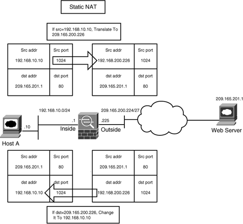
Optionally, the hosts on the lower-security interface can be translated when traffic is destined for a host on the higher-security interface. This method, known as outside NAT, is useful when you want a host on the outside network to appear as one of the internal IP addresses. In Figure 4-24, a host on the outside network, 209.165.201.1, sends traffic to a host on the inside network, 192.168.10.10, by using its global IP address as the destination address. Cisco ASA converts the source IP address to 192.168.10.100 while changing the destination IP address to 192.168.10.10. Because both the source and destination IP addresses are changing, this is also Bidirectional NAT.
Figure 4-24 Outside Network Address Translation
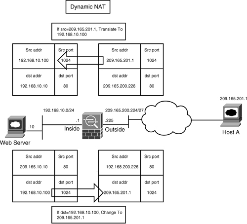
Note
If the packets are denied by the interface ACLs, the security appliance does not build the corresponding address translation table entry.
Port Address Translation
Port Address Translation (PAT) defines a many-to-one address mapping when a packet passes through the security appliance and matches criteria for translation. The security appliance creates the translation table by looking at the Layer 4 information in the header to distinguish between the inside hosts using the same global IP address.
Figure 4-25 illustrates an appliance set up for PAT for the inside network of 192.168.10.0/24. However, only one global address is available for translation. If two inside hosts, 192.168.10.10 and 192.168.10.20, require connectivity to an outside host, 209.165.201.1, the security appliance builds the translation table by evaluating the Layer 4 header information. In this case, because both inside hosts have the same source port number, the security appliance assigns a random source port number to keep both entries unique from each other. This way, when the response from the web server returns to the security appliance, the security appliance knows to which inside host to forward the packets.
Figure 4-25 Port Address Translation
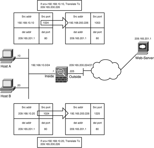
Address Translation and Interface Security Levels
By default, Cisco ASA does not require an address translation policy to be created when the inside machines (host toward the higher security–level interface) need to access the hosts on the outside network (resources toward the lower security–level interface). However, if a packet matches a NAT/PAT policy, the security appliance translates the address. If packets do not match a policy, they are sent out without being translated.
Some organizations mandate that a translation policy be defined before hosts can send traffic through their firewalls. To meet that requirement, you can enable the nat-control feature on the security appliance. If implemented, any traffic trying to pass through the security appliance without an address translation policy is dropped. Even if you do not want to translate an address but the nat-control feature is turned on, you must define a policy to bypasss address translation. Table 4-12 discusses the NAT behavior with or with the nat-control feature when traffic is originated from different security-level interfaces.
Table 4-12 Security Levels and NAT-Control Feature
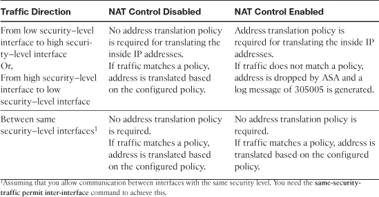
As mentioned in Table 4-12, address translation is not required when traffic passes between the same security–level interfaces, even if the NAT-control feature is enabled. However, if you define a dynamic NAT/PAT policy with the NAT-control feature enabled, then the security appliance performs address translation for the traffic passing between the same security-level interfaces.
Note
If NAT rules are defined on the same security interfaces, then the security appliance does not support any voice over IP (VoIP) inspection engines such as Skinny, SIP, and H.323. Traffic flows from one of the same security interfaces to a different security–level interface are still inspected even if NAT rules are defined.
Packet Flow Sequence
When a packet passes through an appliance configured for address translation, the following sequence of events occurs:
Step 1. The packet arrives at the ingress interface from the end host.
Step 2. The security appliance checks to see whether the packet is a part of an existing connection. If it matches an existing connection, the processing function skips to step 4. If the packet is not a part of an existing connection, and that packet is the first packet in a flow (for example, a SYN packet for TCP), the packet is evaluated against the inbound ACL applied on the ingress interface.
Step 3. If the packet is allowed in, the security appliance first checks to see whether a translation with a global IP matching the destination of the packet exists on the interface where the packet is received. A quick route lookup is done only to determine egress interface. If there is a match, the packet is “virtually forwarded” to the interface of the translated address, skipping the global routing table check. If there is no translation matching the destination IP of the packet on that ingress interface, proceed to step 4.
Step 4. If address translation is enabled and the packet matches the translation criteria, the security appliance creates a translation for the host.
Step 5. On the egress interface, the security appliance consults the routing table to ensure only routes pointing to the egress interface are eligible.
Step 6. The security appliance creates a stateful connection entry for the TCP and UDP packets. The security appliance can, optionally, create a stateful connection entry for ICMP traffic if ICMP inspection is turned on.
Step 7. On the egress interface, packet is transmitted on the physical interface.
Security Protection Mechanisms Within Address Translation
Address translation not only masquerades the original IP address; it also provides protection against TCP connection hijacking for hosts with weak SYN implementation. When a packet enters the higher-security interface and is destined for a lower-security interface during the TCP three-way handshake, the security appliance randomizes the original sequence numbers used by the hosts. This process is illustrated in Figure 4-26. When the host 192.168.10.10 sends a TCP SYN HTTP packet to host 209.165.201.1 with an Initial Sequence Number (ISN) of “12345678”, the Cisco ASA changes the source IP address to 209.165.200.226 and also modifies the ISN to a randomly generated value of “a1b2e3c4”.
Figure 4-26 Randomization of ISN
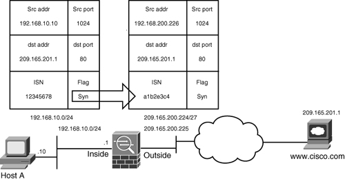
In some deployment scenarios, such as BGP peering with MD5 authentication, it is recommended to turn off the randomization of TCP packets. When two routers establish BGP peering with each other, the TCP header and data payload are 128-bit hashed, using the BGP password. When the sequence number is changed, the peering router fails to authenticate the packets because of the mismatched hash. For more information about BGP MD5 authentication, consult RFC 2385.
Cisco ASA also provides protection against certain types of denial of service (DoS) attacks. By using the embryonic and maximum connection limit, the security appliance can restrict the establishment of new connections to the inside servers. An embryonic connection is a half-opened connection from the client to the server during the TCP three-way handshake. When the number of embryonic connections hits the maximum allowed limit, Cisco ASA starts intercepting the SYN packets from the client to the servers. This process of intercepting the TCP packets is known as TCP interception. It is illustrated in Figure 4-27 and consists of the following seven steps:
Step 1. The client sends a TCP SYN packet destined for the server.
Step 2. The security appliance responds with an ACK on behalf of the server.
Step 3. The client (if legitimate) acknowledges the receipt of the previous packet; the security appliance marks the connection as valid.
Step 4. The security appliance sends a TCP SYN packet destined to the server.
Step 5. The server responds with an ACK to the security appliance.
Step 6. The security appliance acknowledges the receipt of the previous packet and joins both connections transparently without any user interception.
Step 7. The client and the server pass data traffic.
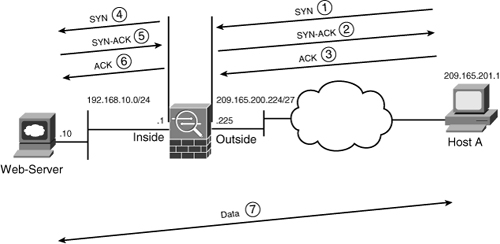
Note
The TCP intercept feature is enhanced in version 8.0 of the security appliance, where you can now use modular policy framework (MPF) to set connection limits. MPF is discussed in Chapter 7 and then in Chapter 11. An example, shown here, illustrates MPF being used to set the maximum connection limit to 1500 and the embryonic connection limit to 2000 for all traffic traversing the outside interface.
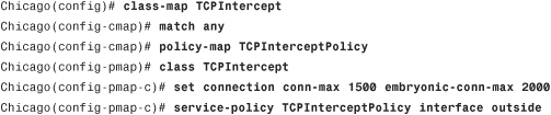
The security appliance can also protect network resources from an unexpected increase in the number of connections by setting maximum limits. This is applicable for both TCP- and UDP-based connections.
Configuring Address Translation
Cisco ASA supports the following five types of address translation, each of which is configured uniquely:
Static NAT
Static NAT defines a fixed translation of an inside host or subnet address to a global routable address or subnet. The security appliance uses the one-to-one methodology by assigning one global IP address to one inside IP address. Thus, if 100 hosts residing on the inside network require address translation, the security appliance should be configured for 100 global IP addresses. Additionally, the inside hosts are assigned the same IP address whenever the security appliance translates the packets going through it. This is a recommended solution in scenarios in which an organization provides services such as email, web, DNS, and FTP for outside users. Using static NAT, the servers use the same global IP address for all the inbound and outbound connections.
Define a static entry via ASDM by navigating to Configuration > Firewall > NAT Rules > Add > Add Static NAT Rule. A new window opens where you can specify the following attributes:
• Original Interface—Specify the interface where the real host or network exists. It is the higher-security interface (such as inside or DMZ) if inside NAT is used or the lower-security interface (such as outside) if outside NAT is implemented. In Figure 4-24, the original host (192.168.10.10) is connected toward the inside interface. If you want to translate its IP address, select inside from the drop-down menu.
• Original Source—Specify the real or pre-translated IP address of the source whose IP address you want to change. Referring back to Figure 4-24, specify 192.168.10.10 as the original source address.
• Translated Interface—Select the interface name that owns a host’s translated IP address. It is the lower-security interface (such as outside) if inside NAT is used or the higher-security interface if outside NAT is implemented.
• Translated Use IP Address—Specify translated or NAT’ed IP address of host. Referring back to Figure 4-24, specify 209.165.200.226 as the translated source address.
In Figure 4-28, a static entry is being created to translate an inside host, 192.168.10.10, to 209.165.200.226. The maximum TCP and UDP simultaneous connection limits are set to 1000, and the embryonic connections are restricted to 100 before the security appliance initiates the TCP intercept mode. The sequence numbers are also randomized. These parameters are defined in the Connection Settings pull-down menu.
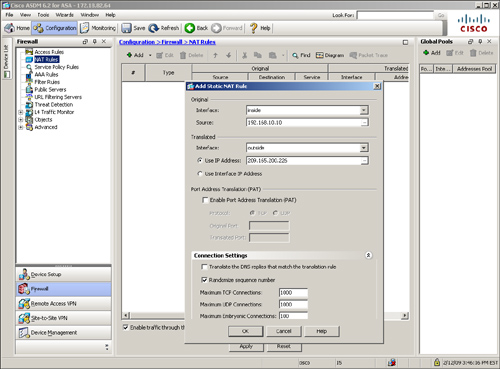
If you prefer to use the CLI, the corresponding configuration of Figure 4-28 is shown in Example 4-32.
![]()
To add a network-based static translation, specify the valid subnets in the static command. As shown in Example 4-34, the security appliance is configured to translate the 192.168.10.0/29 subnet to 209.165.200.232/29. Any host that falls in this range of IP addresses will be assigned an IP address from the 209.165.200.232/29 subnet.
Example 4-33 also illustrates how to set up an outside NAT static entry. An outside host, 209.165.201.1, is translated to an inside address, 192.168.10.100, before the packets enter the inside network.
Example 4-33 Network-Based Inside Static NAT and Outside Static NAT
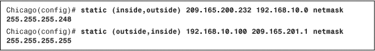
Note
The security appliance does not support outside NAT or PAT if the Cisco CallManager server reside on the inside network and the IP phones connect from the outside network.
Dynamic Network Address Translation
Dynamic NAT assigns a random IP address from a preconfigured pool of global IP addresses. The security appliance uses a one-to-one methodology by allocating one global IP address to an inside IP address. Hence, if 100 hosts reside on the inside network, then you have at least 100 addresses in the pool of addresses. This is a recommended solution in scenarios in which an organization uses protocols that don’t contain Layer 4 information, such as Generic Routing Encapsulation (GRE), Reliable Datagram Protocol (RDP), and Data Delivery Protocol (DDP). After the security appliance has built a dynamic NAT for an inside host, any outside machine can connect to the assigned translated address, assuming that the security appliance allows the inbound connection, as discussed in the “Monitoring Network Access Control” section earlier in this chapter.
Configuration of dynamic NAT is a two-step process:
• Mapping the global pool to real addresses
Define a Global Pool
You must define a pool of translated addresses that you want the pre-NAT hosts to use. You can define a pool of addresses by navigating to Configuration > Firewall > NAT Rules and clicking Add under “Global Pools”, located as a tab to the far right. ASDM opens a new window where you can specify the following attributes:
• Interface—Select the interface name that owns a host’s translated IP address. It is the lower-security interface, such as outside, if inside NAT is used.
• Pool ID—This is a positive number between 1 and 65,535 that is linked to the Dynamic NAT statements so that an address can be allocated from the respective global pool.
• Starting IP Address—Specify a start address to be assigned to the pre-NAT hosts. Because these entries are dynamically created, the security appliance assigns these addresses in round-robin fashion by assigning this address from the pool first.
• Ending IP Address—Specify the last address in the range. After the security appliance assigns the last address to a host, it cannot create additional dynamic NAT translations until a previously allocated address is freed up.
• Netmask—Specify a mask for the translated addresses in the range. This attribute is optional because a default mask of the appropriate address class is used if you don’t specify a value.
Note
Pool ID with a value of 0 (zero) is used to bypass address translation. This option is discussed later in the chapter, in the “Bypassing Address Translation” section.
In Figure 4-29, an administrator wishes to dynamically assign global addresses from a pool of IP addresses ranging from 209.165.200.230 to 209.165.200.237. The assigned pool ID is 1 and this pool of addresses resides toward the outside interface.
Figure 4-29 Defining a Global Pool of Addresses
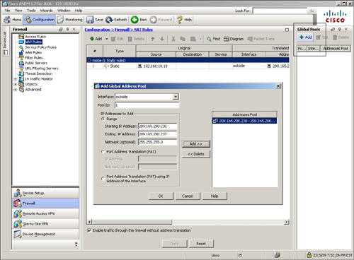
The CLI equivalent of Figure 4-29 is shown in Example 4-34.
Example 4-34 Configuration of Global NAT Pool

Note
When address translation is turned on, the security appliance does proxy ARP for the configured translated addresses. Proxy ARP is a process in which the security appliance answers ARP requests on behalf of other addresses.
Map the Global Pool to Real Addresses
After defining the global address pool, the next step is to identify the original host or network address that you want to translate. This network entity is then mapped to the global pool, defined in the previous step, so that a real address can be translated to one of the addresses in the pool. Browse to Configuration > Firewall > NAT Rules > Add > Add Dynamic NAT Rule to add the pre-NAT addresses and select a previously defined pool. As illustrated in Figure 4-30, the inside subnet of 192.168.10.0/24 is defined as the pre-NAT entity. Under translated global pools, the pool ID of 1 is selected for dynamic NAT.
Figure 4-30 Mapping the Global Pool to Pre-NAT Addresses
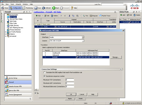
The CLI equivalent of Figure 4-30 is shown in Example 4-35.
Example 4-35 Configuration of Global NAT Pool
![]()
Note
If you want to define an outside dynamic NAT entry via the CLI, you must add the outside keyword in the nat statement after specifying the subnet mask. The outside keyword is used only when translating the source of a packet as it moves from a lower to higher security–level interface.
ASDM automatically sends the outside keyword command when you define an outside dynamic NAT entry via ASDM. You do not have to manually select any options to set this attribute.
Static Port Address Translation
port redirection, is useful when the security appliance needs to statically map multiple inside servers to one global IP address. Port redirection is applied to traffic when it passes through the security appliance from a lower-security interface to a higher-security interface. The outside hosts connect to the global IP address on a specific TCP or UDP port, which the security appliance redirects to the internal server, as shown in Figure 4-31.
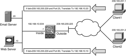
The security appliance redirects traffic destined for 209.165.200.229 on TCP port 80 to 192.168.10.10. Similarly, any traffic destined for 209.165.200.229 on TCP port 25 is redirected to 192.168.10.20.
The security appliance allows the use of either a dedicated IP address or the global interface’s IP address for port redirection.
When port redirection is set up to use the public interface’s IP address, the security appliance uses the same address for
• Address translation for the traffic traversing through the security appliance.
• Traffic destined for the security appliance.
Configuring a static port address translation is similar to defining a static NAT entry. Navigate to Configuration > Firewall > NAT Rules > Add Static NAT Rule and specify the real and translated address in the ASDM window. Select the Enable Port Address Translation (PAT) option and specify the following attributes:
• Protocol—Select the tcp and udp options in protocols to specify which protocol to consider for address translation.
• Original Port—This is the port that the original host is using for its services. For example, if a web server resides on the inside network and uses the default TCP port 80 for web services, then specify 80 as the original port.
• Translated Port—This is the port that the outside users connect to when they need to access the original server. For example, if a web server resides on the inside network and uses the default TCP port 80 for web services, but you want the outside users to connect to TCP port 8080 when they need to connect to this server, then specify 8080 as the translated port.
As illustrated in Figure 4-32, a static PAT entry has been defined for an internal web-server located at 192.168.10.10. The web clients on the public network will connect to the server using the translated address of 209.165.200.229 on TCP port 80.
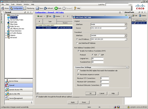
Example 4-36 shows the CLI equivalent output of the configuration steps discussed in Figure 4-32.
Example 4-36 Configuration of Static PAT
![]()
Dynamic Port Address Translation
Using dynamic PAT, the security appliance builds the address translation table by looking at the Layer 3 and Layer 4 header information. It is the most commonly deployed scenario because multiple inside machines can get outside connectivity through one global IP address. In dynamic PAT, the security appliance uses the source IP addresses, the source ports, and the IP protocol information (TCP or UDP) to translate an inside host. As with static PAT, you have the option of using either a dedicated public address or the IP address of an interface for translations. As shown in Figure 4-33, two inside machines are accessing an external web server, using the IP address of the outside interface.
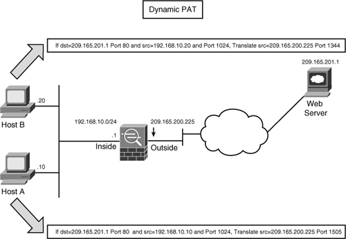
Note
The security appliances randomize the source ports based on an enhancement included in version 8.0(4), 8.1(2), and 8.2(1)
The security appliance supports up to 65,535 PAT translations using a single address. The PAT addresses time out every 30 seconds of inactivity to accommodate as many hosts as possible. The PAT address timeout if non-configurable.
The configuration of dynamic PAT is also a two-step process, similar to setting up a dynamic NAT entry:
• Mapping global pool to real addresses
Define a Global PAT Entry
You must define a public address that you want the inside machines to use for translation. You can define a public address by navigating to Configuration > Firewall > NAT Rules, clicking Add under “Global Pools” and then selecting either “Port Address Translation (PAT)” or “Port Address Translation (PAT) using IP address of the interface”. With the “Port Address Translation (PAT)” option, you can assign a dedicated address to be used by the inside hosts when they need to access resources on the public network. However, the “Port Address Translation (PAT) using IP address of the interface” option uses the IP address of the selected interface for translating inside hosts. Both options analyze the Layer 4 header information within the data packets for creating new translations.
Figure 4-34 illustrates that an administrator is modifying a previously defined global pool. The Pool ID is 1 and already has a range of public addresses from 209.165.200.230 to 209.165.200.237. The administrator had selected Port Address Translation (PAT) using IP address of the interface as the second entry in the pool.
Figure 4-34 Defining a Global PAT Entry
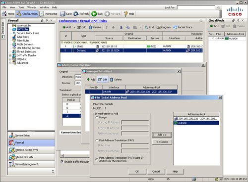
Note
If both dynamic NAT and dynamic PAT are set up using the same Pool ID (or NAT-ID if you are using the CLI), then the security appliance tries to allocate addresses from the pool of addresses first. When all the addresses have been allocated, the security appliance starts using dynamic PAT.
Map Global PAT Entry to Real Addresses
After defining the global PAT entry, you must identify the original host or network address that you want to translate, similar to what you do with dynamic NAT. Example 4-37 shows a security appliance set up to translate the inside network, 192.168.10.0/24, by allocating addresses from the 209.1658.200.230-209.165.200.237 range. It is also using the IP address on the outside interface, 209.165.200.225.
Example 4-37 Configuration of Dynamic PAT
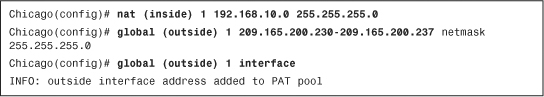
Policy NAT/PAT
Policy NAT/PAT translates the IP address of the packets passing through the security appliance only if those packets match a defined criterion or policy. You define the policy by identifying interesting traffic through the use of ACLs. If traffic matches against the defined entries in the ACL, then the original source or destination address can be translated to a different address. As illustrated in Figure 4-35, an administrator has defined a policy to translate the source IP address to 209.165.200.226 if the packets originate from 192.168.10.10 and are destined for 209.165.201.1. Similarly, if the packets are sourced from 192.168.10.10 and destined for a different address, say 209.165.201.2, the security appliance changes the source IP address to 209.165.200.227.
Figure 4-35 Policy-Based Network Address Translation
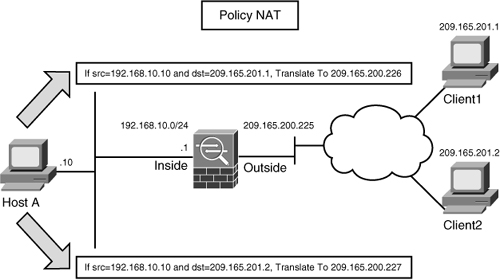
With ASDM, you can set up Policy NAT/PAT for both static and dynamic address translations by navigating to Configuration > Firewall > NAT Rules > Add and then selecting either Add Static Policy NAT Rule or Add Dynamic Policy NAT Rule, respectively. In Figure 4-36 a static policy NAT is being set up to translate the source address from 192.168.10.10 to 209.165.200.226 if the destination address is 209.165.201.1.
Figure 4-36 Policy-Based Static NAT
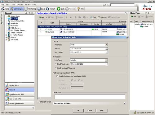
Example 4-38 shows the configuration of static policy NAT where two ACLs are defined to identify the traffic coming from 192.168.10.10 and destined for 209.165.201.1 and 209.165.201.2. The ACLs are then mapped to the static commands to change the source address to 209.165.200.226 if the destination is 209.165.201.1 and change the source address to 209.165.200.227 if the destination is 209.165.201.2
Example 4-38 Configuration of Static Policy NAT
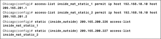
Note
If host-based static policy NAT entries are defined, the access list should contain only a single source IP address to maintain a one-to-one mapping.
Bypassing Address Translation
In many scenarios you want to bypass address translation so that the security appliance does not change the source or the destination address. You may want to bypass address translation if
• You already have address translation defined for the inside network so that hosts can get internet connectivity. However, you do not want to change their addresses if they send traffic to a specific host or network.
• You have the NAT-control feature turned on, but you do not want to translate hosts on a DMZ or any other interface.
Note
Using ASDM, you can enable the NAT-control feature by deselecting the “Enable traffic through the firewall without address translation” option. This option can be found under Configuration > Firewall > NAT Rules, as shown in Figure 4-37. With the CLI, you use the nat-control command to enable the NAT-control feature.
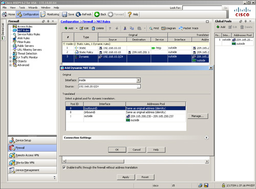
If you want the security appliance to pass some traffic without translating it, you can use Identity NAT or NAT Exemption to bypass address translation.
Identity NAT
Identity NAT preserves the source IP address as it traverses from a higher to a lower security–level interface. Even though the security appliance translates the real address to the same address, in theory it is bypassing address translation by keeping the source address intact. For example, if you want your inside network to keep the same source address when it sends traffic through the security appliances, you can use identity NAT. With identity NAT, hosts located on the other interfaces such as DMZ or outside cannot initiate traffic unless an entry already exists in the translation table.
If you use ASDM, you can define identity NAT by browsing to Configuration > Firewall > NAT Rules > Add > Add Dynamic NAT Rule and then mapping the specified network to a pool with an ID of “0”. In Figure 4-37 an inside network of 192.168.20.0/24 is defined to bypass address translation for all outbound traffic.
When you use the CLI, you enable identity NAT by using the nat 0 command followed by the host or subnet address to be bypassed for address translation, as shown in Example 4-39. The security appliance does not translate the outbound connections from the inside network, 192.168.20.0/24.
Example 4-39 NAT Bypass Using Identity NAT
![]()
NAT Exemption
NAT exemption bypasses address translation for the network entities identified by an ACL. NAT exemption allows both inside and outside hosts to initiate traffic without their source addresses being translated. In Figure 4-38, a security appliance uses dynamic PAT to translate the inside network to its outside interface. However, the administrator does not want to change the addresses when the two email servers send packets to each other.
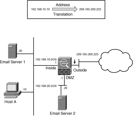
To accomplish this task via ASDM, navigate to Configuration > Firewall > NAT Rules > Add > Add NAT Exempt Rule and specify the following attributes:
• Action—Select Exempt if you want to bypass address translation for the traffic matching the rest of the attributes. If you have already defined exceptions for a network and you would rather that a few hosts not be exempted by NAT, you can define another rule and select the Do Not Exempt option for those hosts.
• Interface—Choose the interface where the hosts with real addresses are connected and need to be exempted by the address translation process. For example, select the inside interface if one of the email servers resides toward that interface.
• Source—Specify the source address of the network entity that you want to exempt from NAT.
• Destination—Specify the destination address of the network entity that you want to exempt from NAT.
• NAT Exempt Direction—Specify the direction of the NAT exemption policy. By default, the “NAT Exempt outbound traffic ...” option is selected which exempts traffic from a higher-security interface to lower-security interface. If you choose the “NAT Exempt inbound traffic...” option then traffic from a lower-security interface to a higher-security interface is exempt.
Note
The security appliance processes NAT exemption rules before identity NAT rules.
As shown in Figure 4-39, a NAT exempt policy is defined for traffic flowing from 192.168.10.20 to 192.168.20.20.
Figure 4-39 NAT Exempt Policy Definition
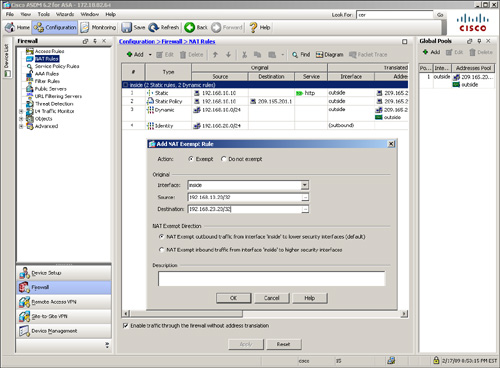
Using CLI, you must define an ACL first to identify interesting traffic and then apply that ACL to the nat 0 statement, as shown in Example 4-40. An ACL called EmailServers identifies the two email servers and then it is linked to the nat 0 statement bound to the inside interface. All other traffic from the inside 192.168.10.0/24 network is translated to the outside interface’s IP address.
Example 4-40 NAT Bypass Using NAT Exemption
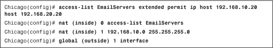
The main difference between identity NAT and NAT exemption is that with identity NAT, the inside hosts must first send traffic outbound, building the identity translation, before outside hosts can respond to that host, whereas with NAT exemption, traffic can be initiated by the hosts on either side of the security appliance. NAT exemption is a preferred method to bypass traffic when it is flowing over a VPN tunnel. This will be discussed in Chapter 16, “Site-to-Site IPSec VPNs,” and Chapter 17, “IPSec Remote Access VPNs.”
Note
In NAT exemption, the ACL cannot contain TCP/UDP port numbers.
NAT Order of Operation
In many network scenarios, it is necessary to configure different types of address translation on a single security appliance. To adapt to those scenarios, the security appliance needs to prioritize certain NAT rules over others to make sure that it knows what to do if there is a conflict. You must maintain the order of these rules as listed below to ensure they are properly set up:
Step 1. NAT exemption—When multiple NAT types/rules are set up, the security appliance tries to match traffic against the ACL in the NAT exemption rules. If there are overlapping entries in the ACL, the security appliance analyzes the ACEs until a match is found.
Step 2. Static NAT—If no match is found in the NAT exemption rules, the security appliance analyzes the static NAT entries in sequential order to determine a match.
Step 3. Static PAT—If the security appliance does not find a match in NAT exemption or static NAT entries, it goes through the static PAT entries until it locates a match.
Step 4. Policy NAT/PAT—The security appliance evaluates the policy NAT entries if it is still not able to find a match on the packet flow.
Step 5. Identity NAT—The security appliance tries to find a match using the identity NAT statement.
Step 6. Dynamic NAT—If the security appliance fails to find a match using the first five rules, it checks to see whether the packets need to be translated using dynamic NAT.
Step 7. Dynamic PAT—The packets are checked against the dynamic PAT rules as the last resort, if all the previously mentioned rules fail.
If the security appliance does not find an exact match by using all the rules and policies, and if the nat-control feature is enabled, it drops the packet and generates a syslog message (305005) indicating such an event has occurred.
Tip
When multiple NAT types are configured on a security appliance, ASDM displays the order of NAT operation under Configuration > Firewall > NAT Rules and under the “#” column.
Integrating ACLs and NAT
Cisco ASA integrates the two core features, ACLs and NAT, to provide a complete security framework. This way, the real IP address of an inside host is hidden from the host on the less trusted networks while appropriate traffic filtering policies are applied. In Figure 4-40, both features are implemented on a security appliance.
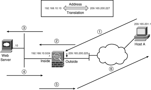
A host on the public network (209.165.201.1) establishes a new connection by sending a packet to an inside web server. The security appliance handles the packet in the following sequence:
Step 1. The packet arrives at the outside interface of the security appliance with a source address of 209.165.201.1 and a destination address of 209.165.200.227. Cisco ASA checks the inbound ACL to make sure that it is allowed in.
Step 2. If the packet is permitted to pass through, the security appliance sends the packet to the NAT engine to determine whether the addresses need to be translated. The destination address is changed to 192.168.10.10.
Step 3. The security appliance creates a connection entry and forwards the packet to the egress (inside) interface after evaluating it against the outbound ACL on the inside interface.
Step 4. The web server replies to Host A, using its source IP address of 192.168.10.10.
Step 5. The packet is forwarded to the NAT engine, which changes the source IP address to 209.165.200.227.
Step 6. The security appliance sends the packet to Host A.
You can use ASDM to define a NAT and an ACL to allow traffic from the web clients on the outside to communicate with the web server on the inside network. Follow these steps:
Step 1. Navigate to Configuration > Firewall > Access Rules > Add and select Add Access Rule. Configure the following Access Rule:
• Interface: Outside
• Action: Permit
• Source: any
• Destination: 209.165.200.227
• Service: http. Click OK when you are finished.
Step 2. Navigate to Configuration > Firewall > NAT Rules > Add and select Add Static NAT Rule. Configure the following policy for the Static NAT Rule:
• Original Interface: inside
• Source: 192.168.10.10
• Translated Interface: outside
• Source: 209.165.200.227. Click OK when you are finished.
Using the CLI, a static NAT entry translates the original IP of the web server from 192.168.10.10 to 209.165.200.227. An ACL named inbound_traffic_on_outside then allows any outside host to establish an HTTP connection to the web server, using its translated address. The ACL is then applied to the outside interface to filter the inbound packets, as shown in Example 4-41.
Example 4-41 Configuration of NAT and Interface ACLs
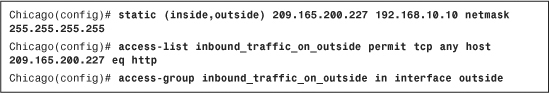
Note
Address translation was not supported in transparent mode until the 8.0 version of code. In the pre-8.0 versions, the nat and static commands were solely used to set embryonic and connection limits in transparent mode.
DNS Doctoring
In many network deployments, the DNS servers and DNS clients are set up for address translation but they are located on different subnets through the security appliance,. This is illustrated in Figure 4-41. The web server (www.securemeinc.com) and the web clients are located toward the inside network, whereas the DNS server is on the outside network. The real IP address of the web server is 192.168.10.10 and the translated public address is 209.265.200.227.
Figure 4-41 DNS and NAT Without DNS Doctoring
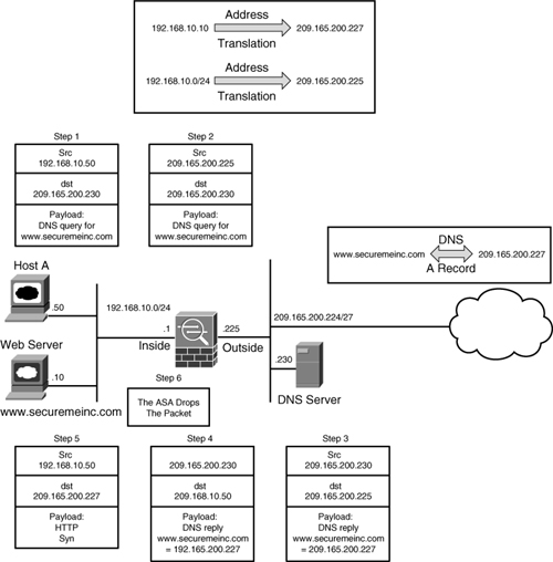
The problem arises when a web client (Host A) tries to access the web server using servers’s hostname. In this scenario, the following sequence of events occurs:
Step 1. Host A sends a request to the DNS server, inquiring about the IP address of the web server.
Step 2. The source IP address is translated to 209.165.200.225, using dynamic PAT or any other form of address translation.
Step 3. The DNS server replies with the translated IP address of the web server (209.165.200.227) as a type A DNS record.
Step 4. The security appliance translates the destination IP address to 192.168.10.50 (Host A’s IP address).
Step 5. The client, not knowing that the web server is on the same subnet, tries to connect to the public IP address.
Step 6. The security appliance drops the packets because the server resides on the inside interface and the packets are destined for the public IP address.
The DNS doctoring feature of Cisco ASA inspects the data payload of the DNS replies and changes the type A DNS record (IP address sent by the DNS server) to an address specified in the NAT configuration. In Figure 4-42, the security appliance modifies the IP address in the payload from 209.165.200.227 to 192.168.10.10 (Step 4) before forwarding the DNS reply to the client. The client uses this address to connect to the web server.
Figure 4-42 DNS and NAT with DNS Doctoring
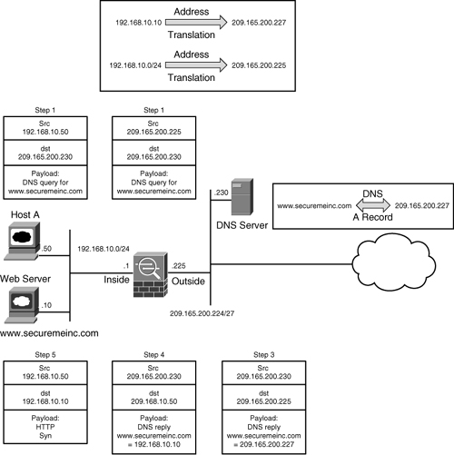
Using ASDM, you can enable the DNS doctoring feature by selecting the Translate the DNS replies that match the translation rule option when you try to add a NAT entry as shown earlier in Figure 4-28. If you prefer to use the CLI, you can add the dns keyword to the static and/or nat commands that are translating the real IP address of the server. In Example 4-42, a static NAT entry is set up to translate a real IP address from 192.168.10.20 to a global IP address, 209.165.200.227. The dns keyword is specified to enable DNS doctoring for this server.
Example 4-42 Configuration of DNS Doctoring

Note
The security appliance also supports DNS doctoring through use of the alias command. However, the recommended method is to use DNS doctoring with static and nat commands because the alias command will be deprecated in the future.
DNS doctoring can also be set up for the outside NAT connections. This is useful in deployments where the DNS server and the content (such as web or email) server reside on the outside network and the clients are located on the inside network, as shown in Figure 4-43.
Figure 4-43 DNS Doctoring for Outside NAT
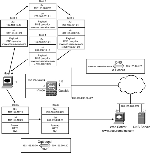
The following sequence of events takes place when a host on the inside network connects to a web server on the outside network:
Step 1. Host A sends a DNS query to the server to resolve www.securemeinc.com.
Step 2. The security appliance translates the source IP address to 209.165.200.225 before forwarding the packet to the DNS server.
Step 3. The DNS server replies with the IP address of the web server, 209.165.201.20, in the data payload.
Step 4. The security appliance changes the embedded IP address to 192.168.10.20 before it forwards the reply to Host A.
Step 5. The client sends a TCP SYN packet to connect to the web server, using 192.168.10.20 as the destination IP address.
Step 6. As the packet passes through, the security appliance changes the destination IP address to 209.165.201.20. The packet gets routed to the Internet before it reaches the web server.
Example 4-43 shows the respective configuration of the security appliance to enable DNS doctoring for outside NAT.
Example 4-43 Configuration of DNS Doctoring for Outside NAT
![]()
Monitoring Address Translations
Cisco ASA provides a rich set of show commands to monitor and troubleshoot issues related to address translation. The most important monitoring command is show xlate, which displays the real (local) address and the mapped (global) IP address assigned to a host. In Example 4-44, the security appliance is translating an inside host located at 192.168.10.10 to 209.165.200.225, using PAT. Cisco ASA changes the source port number from 11085 (local) to 1024 (global) before forwarding the packet to the egress interface. The security appliance also shows the maximum number of simultaneous translations (10) it has performed since the last reboot and the current active translations (1).
Example 4-44 Output of show xlate
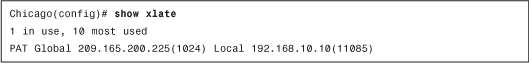
Tip
You can add the debug option at the end of show xlate to display the interfaces to which the translations are bound, along with the connection flags and idle times.
You can use a single command, show local-host, to display connection and translation statistics, as shown in Example 4-45. It displays the network states of each host on the local network. The TCP and UDP flow count counters display the active sessions going through the security appliance from that particular host.
Example 4-45 Output of show local-host
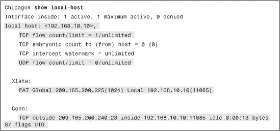
Note
The show local-host all command can be used to see both the connections made to and from the security appliance and the connections made through the security appliance.
Summary
This chapter explained the features available to protect the critical network resources by using two important features: network access control and network address translation. This chapter demonstrated how a security appliance can be configured for both features via the CLI as well as ASDM. Other features such as content filtering and DNS doctoring were discussed to exhibit the robustness of Cisco ASA. This chapter also discussed a number of show commands to monitor and troubleshoot these features.