Chapter 12. Configuring and Troubleshooting Intrusion Prevention System (IPS)
Cisco ASA integrates firewall capabilities with sophisticated intrusion prevention features that provide a deep-packet inspection solution. Cisco Intrusion Prevention System (CIPS) integration makes it possible to effectively mitigate a wide range of network attacks without compromising Cisco ASA’s performance.
This chapter covers Cisco ASA IPS integration, providing several deployment examples and considerations. Additionally, it covers the configuration and troubleshooting of the Adaptive Inspection Prevention Security Service Module (AIP-SSM).
Overview of the Adaptive Inspection Prevention Security Services Module (AIP-SSM) and Adaptive Inspection Prevention Security Services Card (AIP-SSC)
CiscoASA supports the Adaptive Inspection Prevention Security Service Module (AIP-SSM), running Cisco Intrusion Prevention System (CIPS) software version 5.0 or later. One of the major features of CIPS is its capability to process and analyze traffic inline. This qualifies Cisco ASA to be classified as an IPS. The system image file is similar to the ones that run on the Cisco IPS 4200 Series sensors, Cisco IDS Services Module-2 (IDSM-2) for Cisco Catalyst 6500, and Cisco IDS Network Module for Cisco IOS routers.
There are four different AIP-SSM modules:
• AIP-SSC-5—Only supported on the Cisco ASA 5505.
• AIP-SSM-10—Supported on the Cisco ASA 5510 and 5520.
• AIP-SSM-20—Supported on the Cisco ASA 5520 and 5540.
• AIP-SSM-40—Supported on the Cisco ASA 5520 and 5540.
AIP-SSM and AIP-SSC Management
You can manage the AIP-SSM from its management interface port by using Telnet, SSH, or Cisco Adaptive Security Device Manager (ASDM). You can also manage it from the ASA’s backplane by using the session command:
session module-number
The module-number is the slot number in the Cisco ASA. Because there is only one available slot, the module number is always 1. Example 12-1 demonstrates how to open a command session to the AIP-SSM module. The AIP-SSM module prompts the user for authentication credentials.

After the user session is connected to the AIP-SSM, the configuration steps are the same as for any other system running CIPS 5.0 or later software. You can use the show module command in the Cisco ASA to see high-level information about the installed AIP-SSM module (see Example 12-2).
Example 12-2 Output of show module Command

The first highlighted line shows the card type. In this case, the New York ASA 5540 is running an AIP-SSM-20 with serial number 01234567890. The second highlighted line shows the MAC address of the card and the software version it is running. The third highlighted line shows the status of the module, Up, meaning it is operational.
Inline Versus Promiscuous Mode
Cisco ASA supports both inline and promiscuous IPS modes. When configured as an inline IPS, the AIP-SSM module can drop malicious packets, generate alarms, or reset a connection, allowing the ASA to respond immediately to security threats and protect the network. Inline IPS configuration forces all traffic to be directed to the AIP-SSM. The ASA does not forward any traffic out to the network without the AIP-SSM first inspecting it.
Figure 12-1 shows the traffic flow when the Cisco ASA is configured in inline IPS mode.
Figure 12-1 Traffic Flow of Inline IPS Mode

The following is the sequence of events illustrated in Figure 12-1:
Step 1. The Cisco ASA receives an IP packet from the Internet.
Step 2. Because the Cisco ASA is configured in inline IPS mode, it forwards the packet to the AIP-SSM for analysis, assuming that the configured security policies allow this traffic into the protected network. If an ACL is configured in the Cisco ASA to deny this traffic, the packet is never sent to the AIP-SSM.
Step 3. The AIP-SSM analyzes the packet and, if it determines that the packet is not malicious, forwards the packet back to the Cisco ASA.
Step 4. The Cisco ASA forwards the packet to its final destination (the protected host).
When the Cisco ASA is configured in promiscuous IPS mode, the ASA forwards a copy of the packet to the AIP-SSM for inspection; however, the packet makes it to the internal network, depending on the configured security policies. Figure 12-2 shows the traffic flow when the Cisco ASA is configured in promiscuous IPS mode.
Figure 12-2 Traffic Flow of Promiscuous IPS Mode

The following is the sequence of events illustrated in Figure 12-2:
Step 1. The Cisco ASA receives an IP packet from the Internet.
Step 2. Because the Cisco ASA is configured in promiscuous IPS mode, it forwards a copy of the packet to the AIP-SSM for analysis. The Cisco ASA forwards the packet to its final destination (the protected host), assuming that the configured security policies allow this traffic into the protected network. If an ACL is configured in the Cisco ASA to deny this traffic, the packet is never sent to the AIP-SSM.
Step 3. The AIP-SSM analyzes the copy of the packet and, if it determines that the packet is malicious, it can alert the administrator, or take any configured action. The configuration of specific IPS security policies and the respective actions are covered later in this chapter in the “Advanced Features and Configuration” section.
Cisco IPS Software Architecture
The CIPS software uses the Security Device Event Exchange (SDEE) protocol. SDEE is a standardized IPS communication protocol developed by Cisco for the IDS Consortium at the International Computer Security Association (ICSA). Remote applications such as Adaptive Security Device Manager (ASDM), IPS Device Manager (IDM), Intrusion Prevention System Management Console (IPSMC), and Cisco Security Monitoring, Analysis and Response System (CS-MARS) can retrieve events from the sensor through this protocol.
The major components of CIPS software include the following:
• MainApp
• Attack Response Controller (formerly known as the Network Access Controller (NAC))
• Logger
• Transactional Services for Security Device Event Exchange (SDEE)
• NotificationApp
• InterfaceApp
• CLI
Figure 12-3 illustrates the main components of CIPS in correlation with the AIP-SSM.
Figure 12-3 CIPS Software Architecture Overview

MainApp
MainApp is responsible for several critical tasks in the AIP-SSM (as well as all other platforms that support CIPS software). These tasks include the following:
• Initializing all CIPS components and applications
• Scheduling, downloading, and installing software updates
• Configuring communication parameters
• Managing the system clock
• Gathering system statistics and software version information
• Cleanly shutting down/restarting all CIPS services
MainApp is initialized by the CIPS operating system and starts the CIPS applications in the following sequence:
Step 1. Reads and validates dynamic and static configurations.
Step 2. Synchronizes dynamic configuration data to system files.
Step 3. Creates EventStore and the Intrusion Detection Application Programming Interface (IDAPI) shared components.
Step 4. Initializes status event subsystem.
Step 5. Launches IPS applications as stated in the static configuration.
Step 6. Waits until an initialization status event from each application is sent.
Step 7. Generates an error event identifying all applications that did not start, if all status events are not received within 60 seconds.
Step 8. Listens for control transaction requests and processes them accordingly.
MainApp controls the CIPS software installation and upgrades. It also controls network communication parameters, such as the following:
• AIP-SSM hostname
• IP addressing and default gateway configuration for the AIP-SSM command and control interface
• Network access control list
MainApp manages the system clock (whether NTP is configured or not) and collects system statistics.
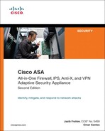
SensorApp
SensorApp is the application responsible for the analysis of network traffic, examining it for any malicious content. The packets flow through it from the Gigabit Ethernet network interface on the AIP-SSM, which is directly connected to the Cisco ASA backplane.
If the Cisco ASA AIP-SSM configuration is set for promiscuous mode, the packets are discarded after processing by SensorApp. If configured for inline operation, the packets are either forwarded back to the Cisco ASA or dropped according to the defined policy.
SensorApp has two modules crucial for the operation of the AIP-SSM or any other device running CIPS:
• Analysis Engine
The Virtual Sensor is the Analysis Engine Configuration Module, which handles the AIP-SSM configuration. This module interprets the configuration and maps it into internal configuration objects. Figure 12-4 illustrates both of these modules.
Figure 12-4 SensorApp Virtual Sensor and Virtual Alarm
In CIPS, a new protocol is introduced, called the Intrusion Detection Configuration (IDCONF) protocol. IDCONF provides clean, consistent, and accurate signature definitions. This replaces the old IDIOM framework in previous versions. It supports multiple layers of parameters to ensure that a signature is defined in terms that are understandable and valid for the inspection engines. The Virtual Alarm is the alarm channel module, which is responsible for processing all signature events generated by the traffic inspector engine. The primary function of the Alarm Channel Module is to generate alarms for each event as it is passed. Event or alarm filters may be configured and are processed by the alarm channel module, as illustrated in Figure 12-4.
Attack Response Controller
The Attack Response Controller is the application responsible for communicating with the Cisco ASA or any other supported device while shunning (blocking) connections if the AIP-SSM is configured in promiscuous mode.
One of the functions of the Attack Response Controller is to forward shunning information to other IPS devices on the network to collectively control network access devices. IPS sensing devices that perform this operation are referred to as master blocking sensors.
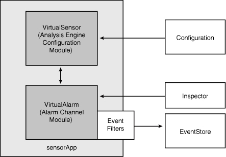
AuthenticationApp
AuthenticationApp, as its name suggests, is the process that controls user authentication on the AIP-SSM or any other device running Cisco IPS 5.x and later software. Additionally, it administers all the user accounts, privileges, Secure Shell (SSH) keys, and digital certificates, while also controlling what authentication method is used.
As illustrated in Figure 12-5, AuthenticationApp controls authentication when the user connects via Telnet, SSH, a session through ASA, ASDM, IDM, or IDSMC.
Figure 12-5 AuthenticationApp Architecture
cipsWebserver
The CIPS web server (cipsWebserver) within AIP-SSM provides configuration support for IDM and provides support for SDEE transactions, such as the following:
• Reporting security events
• Receiving IDCONF transactions
• Processing IP logs
ASDM is hosted and controlled by the Cisco ASA; however, it launches IDM, which uses SDEE to communicate with the AIP-SSM hosted by the CIPS web server. The CIPS web server supports HTTP 1.0 and 1.1 running Secure Sockets Layer (SSL)/Transport Layer Security (TLS).
Logger
The AIP-SSM logs alert, error, status, and debug messages, as well as IP logs. These messages and IP logs are accessible through the CLI and SDEE clients such as IDM, Cisco Security Manager (CSM), and CS-MARS. Logger sends log messages with the following five levels of severity:
• Debug
• Timing
• Warning
• Error
• Fatal
These messages are written to the following file on AIP-SSM module:
/usr/cids/idsRoot/log/main.log.
Note
To access this file, you must be logged in with the service account. Instructions on how to create the service account are discussed later in this chapter, in the “User Administration” section. These messages are mostly used by Cisco TAC engineers for troubleshooting purposes.
Messages that are generated at warning level or above are converted into evErrors and inserted into the Event Store.
EventStore
All IPS events are stored in the EventStore with a time stamp and a unique ascending identifier. Additionally, CIPS internal applications write log, status, and error events into the EventStore.
Note
IPS alerts are written only by the SensorApp application.
The EventStore is designed to store CIPS events in a circular fashion. In other words, when it reaches the configured size, the oldest events are overwritten by new events and log messages.
Note
In CIPS code, the EventStore is reduced to 30 MB from 4 GB in earlier code.
CtlTransSource
SDEE and HTTP remote-control transactions are handled by an internal application called CtlTransSource (formerly known as TransactionSource). It handles all TLS communications with external management servers and monitoring systems. CtlTransSource performs basic authentication to remote management applications and monitoring systems. When an application attempts a remote-control transaction, IDAPI redirects the transaction to CtlTransSource.
Configuring the AIP-SSM
You can configure the AIP-SSM by using the command line interface (CLI) or ASDM. The following sections introduce the CIPS CLI and then cover step-by-step instructions on how to configure the AIP-SSM.
Introduction to the CIPS CLI
The CIPS CLI provides a user interface for all direct connections to the AIP-SSM (e.g., Telnet, SSH, and session from the ASA). This section covers
• How to log in to the AIP-SSM via the CLI
• Initial AIP-SSM configuration
Logging In to the AIP-SSM via the CLI
You can connect to the AIP-SSM CLI via the ASA backplane by using the session command, or by initiating an SSH or Telnet connection via the external management Ethernet port.
The default username is cisco and the default password is cisco. The user is forced to change his password after the first login. Example 12-3 shows the user cisco successfully logging in to the AIP-SSM CLI via the ASA backplane, using the session command.
Example 12-3 Logging In to the CLI

Note
There are four major user account roles that determine which operations a user is allowed to perform. They are covered later in this chapter under “User Administration.”
CLI Command Modes
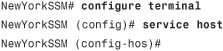
The CIPS CLI is similar to the Cisco ASA and IOS CLIs. It has a configuration command mode that you enter by invoking the configure terminal command. Example 12-4 demonstrates how to enter into global configuration mode.
Example 12-4 Entering Configuration Mode
![]()
The (config)# prompt is displayed after you invoke the configure terminal command.
As in Cisco IOS and ASA, you can display the help for a specific command by typing a question mark (?) after the command. You can also type a question mark to view the valid keywords that complete the command. There are certain commands that generate user interactive prompts. An example of this is the setup command, which is covered in the following section.
Initializing the AIP-SSM
Before the AIP-SSM can communicate with any management station and start analyzing data from the network, you must first configure basic settings with the setup command. The AIP-SSM first displays the current configuration and then generates user interactive prompts that guide you to complete the initial settings.
Note
The default input is displayed inside brackets, [ ]. To accept the default input, press Enter.
Example 12-5 includes the output of the setup command.
Example 12-5 Configuring Initial Settings with the setup Command


Follow these steps after the AIP-SSM prompt asks whether you would like to continue with the configuration dialog:
Step 1. The configuration dialog asks you to enter the hostname to be assigned to the AIP-SSM. The default hostname is sensor. Enter the new hostname (case sensitive) as follows:
Enter host name[sensor]: NewYorkSSM
Step 2. You are asked to enter the IP address and default gateway for the management interface of the AIP-SSM. The default IP address is 10.1.9.201 and the default gateway is 10.1.9.1. Enter the IP address and gateway configuration in the following format:
<ip address>/<mask-bits>,<gateway>
The IP address 192.168.10.28 with a 24-bit mask and gateway of 192.168.10.1 is entered in the following example:
Enter IP interface[10.1.9.201/24,10.1.9.1]:
192.168.10.28/24,192.168.10.1
Step 3. Telnet services are disabled by default. The AIP-SSM allows you to enable Telnet services at this point:
Enter telnet-server status[disabled]:enable
Note that the Telnet protocol is not a secure protocol. SSH should be used instead of Telnet.
Step 4. The default web server port is TCP port 443 (because it is the default for most web servers that support SSL/TLS). The configuration dialog enables you to change the port at this point:
Enter web-server port[443]:
The default port is selected in this example.
Step 5. The configuration dialog prompts you to modify the current access list. Enter yes to add or delete hosts or networks that will be allowed to communicate with the AIP-SSM.

The 192.168.10.0/24 network is added to the list in this example.
Step 6. After adding or deleting entries to your access list, the configuration dialog prompts you to change the clock settings. In the following example, NTP is enabled:

The NTP key ID is set to 1, the key is cisco, and the NTP server address is 192.168.10.123.
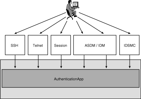
Step 7. You can also modify daylight savings time settings. The default is recurring, which automatically adjusts the time:
Step 8. The configuration dialog asks you to specify the time zone to be displayed when standard time is in effect:
![]()
Step 9. The last step is to modify the monitored interface. In case of the AIP-SSM, the only interface used for monitoring is the internal Gigabit Ethernet interface:
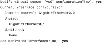
Step 10. The AIP-SSM displays a summary of the configuration entered:
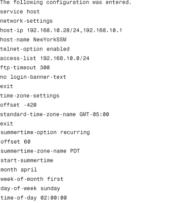

From the menu, you can select any of the available options:
• Go to the command prompt without saving the configuration.
• Return back to the setup without saving the configuration.
• Save the configuration and exit setup.
Select option 2 if you are satisfied with the configuration and you want to save it in the system.
You can use the Startup Wizard in ASDM 6.x or later to set up or to modify an AIP-SSM that has already been configured. However, it cannot be used for initializing a new (not configured) AIP-SSM. You must use the setup command to initialize a new AIP-SSM. To set up or modify the AIP-SSM through ASDM, navigate to Configuration > IPS > Sensor Setup > Startup Wizard and click Launch Startup Wizard. The Startup Wizard leads you through similar steps, followed by the setup CLI command. It enables you to configure basic settings, configure interfaces, create virtual sensors, create policies, assign policies and interfaces to the virtual sensor, and save your changes to the AIP-SSM.
User Administration
Different types of users can be configured in the AIP-SSM with different roles associated with them. This section covers the AIP-SSM user administration.
User Account Roles and Levels
Each AIP-SSM user account has a role associated to it. A total of four roles can be assigned to a specific account:
• Operator
• Viewer
• Service
Administrator Account
The administrator account has the highest privilege level. Users with this role are able to do the following:
• Add users
• Assign passwords
• Control all interfaces on the AIP-SSM
• Configure IP addressing
• Add and delete hosts allowed to connect to the AIP-SSM
• Tune signatures
• Perform all virtual sensor configurations
• Configure shunning
Operator Account
The operator account has the second highest privilege level. These users can view the configuration and statistics. They can also perform some administrative tasks such as modifying their own passwords, tuning signatures, and configuring shunning.
Viewer Account
Users with viewer privileges can view events and some configuration files. They can also change their own passwords.
IPS monitoring applications require viewer access only to perform their monitoring operations. However, if the application is used to perform administrative tasks, a higher privilege account is needed.
Note
The viewer account has the lowest of the privilege levels.
Service Account
The service account does not have direct access to the AIP-SSM CLI. It has access to a bash shell, which enables it to perform specific administrative tasks on the AIP-SSM. This account is not enabled by default.
Note
Only one service account can be configured in the AIP-SSM and any other device running CIPS software. The service account should be created only at the request of the Cisco Technical Assistance Center (TAC).
Adding and Deleting Users
This section guides you on how to create and delete users on the AIP-SSM. It also shows you how to assign different privilege levels to users, depending on their roles.
Complete the following steps to add a user using ASDM:
Step 1. Log in to ASDM, navigate to Configuration > IPS > Sensor Setup > Users, and click on Add. The Add User dialog box shown in Figure 12-6 is displayed.

Step 2. Enter the username in the Username field; viewuser is the username used in this example.
Step 3. Select the user role in the User Role pull-down menu. You can select from Administrator, Operator, Service, and Viewer. The user in this example is configured with Viewer privileges.
Step 4. Enter and confirm the password for the new user under the Password section.
Step 5. Click OK.
Step 6. Click Apply to apply the configuration changes.
Step 7. Click Save to save the configuration.
Alternatively, you can add users on the AIP-SSM via the CLI by using the username command. The following is the command syntax:
username name [password password] [privilege privilege]
Example 12-6 demonstrates how to create the service account, called service with a password of 0plm(OKN.
Example 12-6 Creating the Service Account Using the CLI

Example 12-7 demonstrates how two accounts are created and assigned operator and viewer roles, respectively.
Example 12-7 Creating Other Accounts Using the CLI

A user called opuser is created and assigned operator role privileges, and a user called viewuser is created and assigned viewer privileges.
Note
Usernames must begin with an alphanumeric character and can be 1 to 64 characters in length. The minimum password length is 6 characters, and passwords can be up to 32 characters in length. All characters except spaces and the question mark (?) are allowed to be used in passwords.
Deleting Users
To delete users in the AIP-SSM through ASDM navigate to Configuration > IPS > Sensor Setup > Users, select the user to be deleted, and click the Delete button. If using the CLI, use the no username username command. Example 12-8 demonstrates how the opuser is deleted from the AIP-SSM.
Example 12-8 Deleting a User via the CLI
![]()
Changing Passwords
To change a user’s password in the AIP-SSM through ASDM, navigate to Configuration > IPS > Sensor Setup > Users, select the user, and click the Edit button. Select the Change the Password to Access the Sensor button and enter the new password.
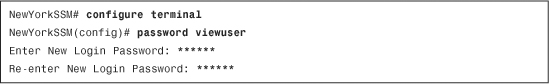
Using the CLI, you can change your own or other user passwords by using the password command. To change the password for another user, you must be logged in through an account with administrator privileges. Example 12-9 demonstrates how the AIP-SSM administrator changes the password for user viewuser.
Example 12-9 Changing viewuser’s Password
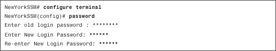
Example 12-10 demonstrates how you can change your own password by just invoking the password command from configuration mode.
Example 12-10 Changing Your Own Password
AIP-SSM Maintenance
This section includes information on administrative maintenance tasks on the AIP-SSM. These tasks include the following:
• Adding trusted hosts to connect to the AIP-SSM
• Upgrading the CIPS software and signatures via the CLI and ASDM
• Displaying software version and configuration information
• Backing up the AIP-SSM configuration
• Displaying and clearing events
Adding Trusted Hosts
For a device to be able to connect to the AIP-SSM for management and monitoring purposes, it needs to be added to the trusted host list. To use ASDM to add trusted hosts that will be able to communicate with the AIP-SSM, navigate to Configuration > IPS > Sensor Setup > Allowed Hosts/Networks and click on Add to add the new hosts or networks. If using the CLI, complete the following steps:
Step 1. Enter configuration mode and invoke the service host command. You will be placed into host configuration mode.
Step 2. Invoke the network-settings command to start adding entries to the ACL for hosts or networks allowed to connect to the AIP-SSM:
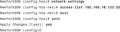
In this example, a host with IP address 192.168.10.123 is added to the ACL.
After you exit from both configuration modes, the AIP-SSM prompts you to apply the changes to the configuration. Enter yes if the configuration parameters are correct.
SSH Known Host List
For any any SSH server to communicate with the AIP-SSM, you must first add it into the SSH known host list. To add an SSH known host key through ASDM, navigate to Configuration > IPS > Sensor Management > SSH > Known Host Keys and click on Add to add the SSH host key.
If using the CLI, the ssh host-key command can be used to add a host to the AIP-SSM SSH known host list. Example 12-11 shows how a host with IP address 192.168.10.33 is added to the NewYork SSM.
Example 12-11 Adding an Entry to the SSH Known Host List

The AIP-SSM asks the administrator to confirm the addition of the SSH host entry. Type yes or press Enter to confirm. The SSH host must be accessible when this command is issued.
TLS Known Host List
The CIPS software enables you to restrict what systems are able to establish a TLS/SSL session to the AIP-SSM.
To use ASDM to add a TLS trusted host to the AIP-SSM, navigate to Configuration > IPS > Sensor Management > Certificates > Trusted Hosts and click Add to add the new host. If using the CLI, use the tls trusted-host command. Example 12-12 demonstrates how to add a TLS host configured with IP address 192.168.10.34. The AIP-SSM does an SSL/TLS exchange with the specified host to obtain its SSL/TLS certificate.
Example 12-12 Adding a TLS Known Host
![]()
Upgrading the CIPS Software and Signatures
You can apply the CIPS software service packs and signature updates using any of the following supported protocols:
• File Transfer Protocol (FTP)
• Hypertext Transfer Protocol (HTTP)
• Hypertext Transfer Protocol Secure (HTTPS)
Note
If HTTPS/SSL is used, a trusted TLS host entry must be added for the server from which you will retrieve the service pack or signature update file.
You can perform one-time upgrades or schedule recurring automatic upgrades.
One-Time Upgrades
To use ASDM to upgrade the AIP-SSM, navigate to Configuration > IPS > Sensor Management > Update Sensor. The screen shown in Figure 12-7 is displayed.
Figure 12-7 Upgrading the AIP-SSM Through ASDM
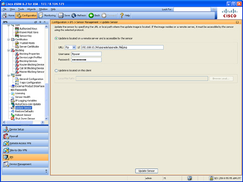
In the example illustrated in Figure 12-7, the FTP protocol is used. The FTP URL is ftp://192.168.10.34/upgrade/upgrade_file.pkg, and the FTP username is ftpuser.
If using the CLI, the upgrade command can be used to apply service packs and signature updates to the AIP-SSM. The following is the command syntax:
upgrade source-url
The source-url is the location where the AIP-SSM retrieves the upgrade file.
The following is the URL syntax if FTP is used:
ftp:[[//username @]location]/relativeDirectory/filename
or
ftp:[[//username@]location]//absoluteDirectory/filename
The syntax for HTTP is as follows:
http:[[//username@]location]/directory]/filename
The syntax for HTTPS is as follows:
https:[[//username@]location]/directory]/filename
The syntax for SCP is as follows:
scp:[[//username@]location]/relativepath]/filename
or
scp:[[//username@]location]/absolutepath]/filename
You are prompted to enter the user’s password when invoking the previously discussed commands. An absolute path is created whenever a link uses the full URL of an object or page. For instance, https://myaipssm.com/ is an absolute path. In contrast, the relative path points to a file or directory in relation to the present file or directory (folder).
Tip
If you enter just the upgrade command followed by a protocol prefix (ftp:, http:, https:, or scp:), the CLI prompts you for all the required information.
In Example 12-13, a signature update is retrieved from the HTTP server that was previously entered into the TLS trusted list (192.168.10.34). A user called httpsuser is being used for authentication purposes. After invoking the command, the AIP-SSM prompts you to enter the password for the HTTPS server user.
Example 12-13 Applying Signature Updates

Scheduled Upgrades
As a best practice, you may want to configure automatic service pack upgrades or signature updates. This eases administration and provides a mechanism to make sure that your AIP-SSM is running updated signatures.
Note
Cisco offers a service where customers can subscribe to obtain IPS signatures shortly after security threats and vulnerabilities are announced. For more information, visit http://www.cisco.com/security.
Automatic updates do not work with Windows FTP servers configured with DOS-style paths. Make sure the server configuration has the UNIX-style path option enabled rather than DOS-style paths.
In the example illustrated in Figure 12-8, the goal is to configure the AIP-SSM module in the NewYork ASA appliance to automatically retrieve signature updates every Monday, Wednesday, and Friday at 1:00 a.m.
Figure 12-8 Scheduled Upgrades

Take the following steps on each device to achieve this goal when using ASDM:
Step 1. Log in to ASDM and navigate to Configuration > IPS > Sensor Management > Auto/Cisco.com Update. The screen shown in Figure 12-9 is displayed.
Figure 12-9 Scheduling Upgrades Using ASDM

Step 2. Select the Enable Auto Update from a Remote Server option.
Step 3. Enter the IP address of the remote server in the IP Address field. The server’s IP address in this example is 192.168.1.188.
Step 3. Select the protocol to be used using the File Copy Protocol pull-down menu. The SCP protocol is used in this example.
Step 4. Enter the directory where the updates will be stored in the remote server, using the Directory field. The directory in this example is called updates.
Step 5. Enter the username and password of the remote server user, using the Username and Password fields respectively. The username in this example is scpuser.
Step 6. Configure the start time and frequency for the automatic updates under the Schedule section. In this example, the AIP-SSM module in the NewYork ASA appliance has been set to automatically retrieve signature updates every Monday, Wednesday, and Friday at 1:00 a.m.
Step 7. Click Apply to apply the configuration changes.
Step 8. Click Save to save the configuration.
Take the following steps on each device to achieve this goal when using the CLI:
Step 1. The IPS signature update from Cisco.com is downloaded and saved on the management server. To enable automatic upgrades and configure auto-upgrade settings, go into service host configuration mode and enable the auto-upgrade option as follows:
NewYorkSSM(config)# service host
NewYorkSSM(config-hos)# auto-upgrade user-server
Step 2. Specify the IP address of the server from which the AIP-SSM will retrieve the update file. In this case, the server is 192.168.1.188:
NewYorkSSM(config-hos-ena)# ip-address 192.168.10.188
Step 3. Specify the file copy protocol used to download files from the server. SCP is used in this example:
NewYorkSSM(config-hos-ena)# file-copy-protocol scp
Step 4. Define the username for authentication on the 192.168.10.188 server. The user in this example is called scpuser:
NewYorkSSM(config-hos-ena)# user-name scpuser
Step 5. Enter the user password for authentication on the 192.168.10.188 server with the password command. The AIP-SSM prompts you to enter and confirm the password:
![]()
Step 6. Specify the directory where upgrade files are located on the server. A leading forward slash (/) indicates an absolute path. The directory in this example is called updates and the update file is called sigupdatefile.pkg:
NewYorkSSM(config-hos-ena)# directory updates/
Step 7. You can configure two types of scheduled updates:
• Calendar based—Specify what days and times of the week the AIP-SSM is to attempt the updates.
• Periodic—Configure the time that the first automatic upgrade should occur, and how long the AIP-SSM will wait between automatic upgrades.
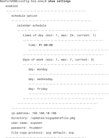
In this example, the AIP-SSM will automatically retrieve signature updates every Monday, Wednesday, and Friday at 1:00 a.m.:

Step 8. Use the show settings command to view and confirm all the settings entered:
Step 9. Exit configuration mode. You will be asked to apply the changes. Enter yes if the information is correct.

Displaying Software Version and Configuration Information
You can use the show version command to display the version of the CIPS software, signature packages, and IPS processes running on the AIP-SSM. Example 12-14 shows the output of the show version command at the NewYorkSSM.
Example 12-14 Output of AIP-SSM show version Command
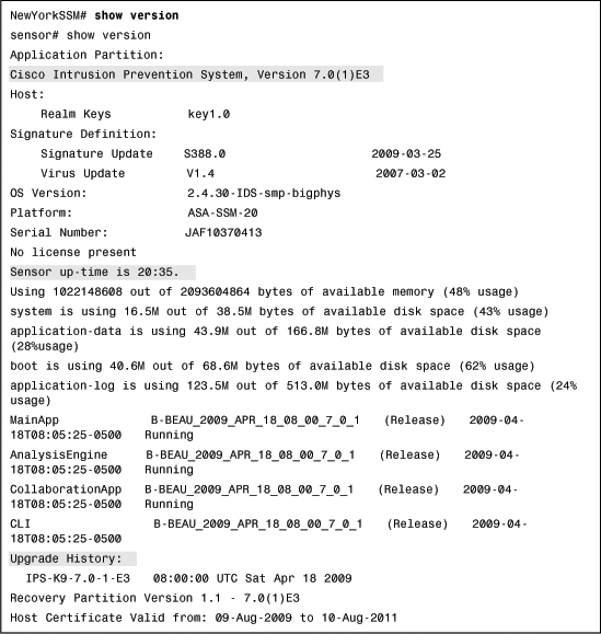
The first shaded line in Example 12-14 shows the CIPS software version running on the AIP-SSM. The second shaded line shows that the AIP-SSM has been up for 20 hours and 35 minutes. The third shaded line shows information about previous upgrades and updates to this AIP-SSM. Other information such as disk and memory utilization is also displayed.
To display the software version when using ASDM, navigate to Home and select the Intrusion Prevention tab. This screen provides information about the state of the sensor according to the gadgets that you choose to display. Each gadget displays the local host time. The gadgets contain the following information:
• Sensor Information—Including the version, IP address, device type, and other information.
• Sensor Health—Includes high-level sensor and network security health information.
• Licensing—Includes the status of the license key, signature updates, and signature engine updates.
• Interface Status—Shows information about the management and sensing interfaces.
• Network Security—Displays alert counts and average and maximum threat and risk ratings.
• Top Applications—Shows the top ten applications the AIP-SMM has discovered.
• CPU, Memory, & Load—Shows the sensor load, CPU, memory, and disk usage for the AIP-SSM.
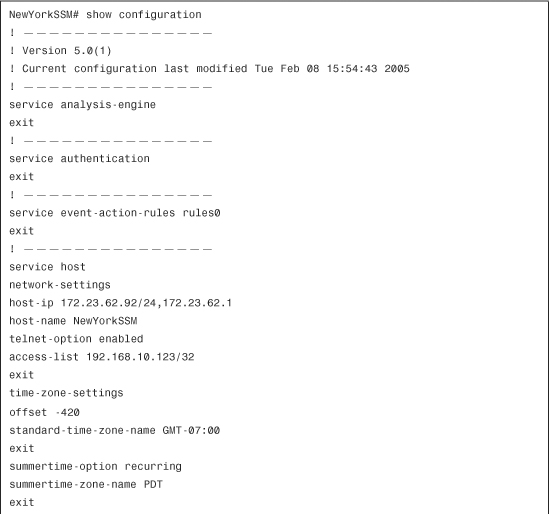
You can use the show configuration command to display the current configuration on the AIP-SSM, as shown in Example 12-15.
Example 12-15 Output of AIP-SSM show configuration Command


Backing Up Your Configuration
It is recommended that you back up your configuration on a regular basis. You can back up your configuration to the local Flash on the AIP-SSM or to a remote server.
Use the copy current-config backup-config command to make a backup of the current configuration to a file (called backup-config) locally stored on the AIP-SSM. You can merge the backup configuration file with the current configuration file or overwrite the current configuration file with the backup configuration file. In Example 12-16, the AIP-SSM merges the backup configuration into the current configuration.
Example 12-16 Merging the Backup Configuration
![]()
In Example 12-17, the AIP-SSM overwrites the backup configuration file into the current configuration file.
Example 12-17 Overwriting the Backup Configuration into Current AIP-SSM Configuration
![]()
As a best practice, you should back up your configuration file to an external server. In the following example, SecureMe’s NewYork AIP-SSM copies a backup of its configuration file to FTP server 192.168.10.159.
Example 12-18 shows the command entered on the AIP-SSM.
Example 12-18 Backing Up the Configuration to an FTP Server
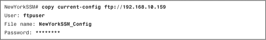
The configuration is successfully copied to a file named NewYorkSSM_Config on the FTP server 192.168.10.159. The AIP-SSM prompts the administrator to enter the FTP user, filename, and password.
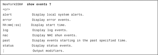
Displaying and Clearing Events
The show events command enables you to view the events stored in the AIP-SSM’s local event log. After this command has been invoked, all the events are displayed as a live feed (to exit, press Ctrl-C). Example 12-19 lists all the available options for the show events command.
Example 12-19 show events Command Options
In Example 12-20, the AIP-SSM displays past events since 8:00 a.m.
Example 12-20 Displaying Past Events

To show IPS events using ASDM, navigate to Monitoring > IPS > Sensor Monitoring > Events, as shown in Figure 12-10.
Figure 12-10 Displaying IPS Events Through ASDM
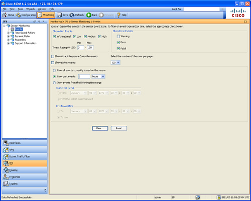
The following are the fields displayed in Figure 12-10:
• Show Alert Events—Enables you to configure the level of alert to be displayed (informational, low, medium, or high). By default, all levels are enabled.
• Threat Rating (0-100)—Used to configure the range (minimum and maximum levels) of the threat rating value.
• Show Error Events—Used to configure the type of errors to be displayed (warning, error, or fatal). By default, all levels are enabled.
• Show Attack Response Controller Events—This was formerly known as Network Access Controller events. This option is disabled by default.
• Show Status Events—Used to show status events. This option is disabled by default.
• Select the Number of the Rows per Page—Enables you to configure how many rows of IPS events are to be displayed per page. The valid range is 100 to 500 and the default is 100.
• Show All Events Currently Stored on the Sensor—Used to retrieve all events stored on the AIP-SSM.
• Show Past Events—Enables you to configure a specified number of hours or minutes within which you can view past events.
• Show Events from the Following Time Range—Used to retrieves events from within the specified time range.
Click View to view the events based on the previously configured options.
You can clear events stored locally in the AIP-SSM by clicking the Reset button or by using the clear events CLI command, as demonstrated in Example 12-21.

The AIP-SSM displays a warning message asking you to confirm the removal of all the events stored on the system because they will be lost if they have not been retrieved by a management or monitoring device.
Advanced Features and Configuration
This section covers advanced configuration topics and features on the AIP-SSM CIPS software. These topics include the following:
• Shunning
• Cisco Security Agent integration
Custom Signatures
The capability to create custom signatures provides you with more flexibility in identifying security threats and network misconduct in a very effective fashion. To create custom signatures, you must know what exactly you want to detect in your network. This section demonstrates how to create a TCP custom signature.
Figure 12-11 illustrates our first example.
Figure 12-11 Custom Signatures Example
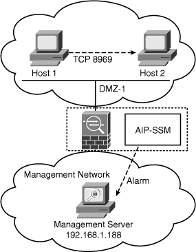
In this example, the security administrator knows that a new vulnerability exists whereby a machine can compromise other hosts and install malicious software while creating a TCP connection on port 8969. Unfortunately, this port is used by other critical applications in the network. The idea is to create a custom signature to detect this behavior, generate an alarm, and report it to a management station from hosts that are not supposed to send any traffic on TCP port 8969. In Figure 12-11, a custom signature on the AIP-SSM triggers an alarm if Host 1 attempts to establish a connection to Host 2 over TCP port 8969. Take the following steps to accomplish this task with ASDM:
Step 1. Log in to ASDM and navigate to Configuration > IPS > Policies > Signature Definitions > sig0 > All Signatures.
Step 2. Click Add to add a new signature. The dialog box shown in Figure 12-12 is displayed.
Figure 12-12 Add Signature Dialog Box

Step 3. Custom signature identifier values are in the range of 60000 to 65000. In this example, the signature identifier is 60088.
Step 4. The SubSignature ID identifies a more granular version of a broad signature. The value can be anything from 0 to 255 (the number 0 is used in this example).
Step 5. The Alert Severity can be High, Informational, Medium, or Low. In this example, the Alert Severity is set to Medium.
Step 6. The Sig Fidelity Rating is used to define how well this signature might perform in the absence of specific knowledge of the target. The value is 0 to 100. In this example, the default value (75) is used.
Step 7. The Promiscuous Delta is used to define the seriousness of the alert. This example uses the default value (0).
Step 8. Enter the name for the new custom signature under the Signature Name field. The signature name in this example is TCP port 8969 Custom Signature.
Step 9. The Alert Notes field enables you to enter a note to be included within an alert produced by this signature. In this example, the alert note configured is Malware in TCP 8969.
Step 10. The User Comments field enables you to add custom comments about this signature.
Step 11. The Release field shows the software release in which the signature first appeared, in this case, the word custom is displayed for a custom signature.
Step 12. The Event Action field enables you to configure the actions the sensor takes when it responds to events. In this case, the default action is configured (Produce Alert).
Step 13. Enter the regular expression string under the Regex String field. In this example, the signature is configured to match the malwareconnect string.
Step 14. Enter the service ports under the Service Ports field. In this example, port 8969 is used.
Step 15. The Direction field enables you to configure the direction in which the packet will be inspected. In this example, the direction is To Service.
Step 16. Click OK to add the new signature.
The following are the steps necessary to add this custom signature with the CIPS CLI:
Step 1. Select the signature engine and signature identifier. Log in with a user that has administrator privileges and enter into signature definition submode:

The signature ID for the new custom signature is 60088. The subsignature ID is 0 because we will have only one signature ID for this example.
Step 2. Enter into signature description submode and define a name for the new signature:
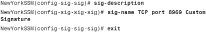
The new signature name is TCP port 8969 Custom Signature.
Step 3. Define the service port under the string-tcp engine configuration, as well as the direction of the connection, as follows:
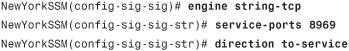
The direction is configured with the to-service option. If you select this option, the AIP-SSM inspects connections from all clients to the server listening on port 8969.
Step 4. Enter the regular expression (regex) string to search for in the TCP packet:
NewYorkSSM(config-sig-sig-str)# regex-string malwareconnect
NewYorkSSM(config-sig-sig-str)# exit
In this case, the offending host sends a known stream to its victim (malwareconnect). After this is detected, the AIP-SSM generates an alarm and alert the administrator.
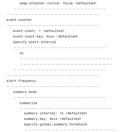
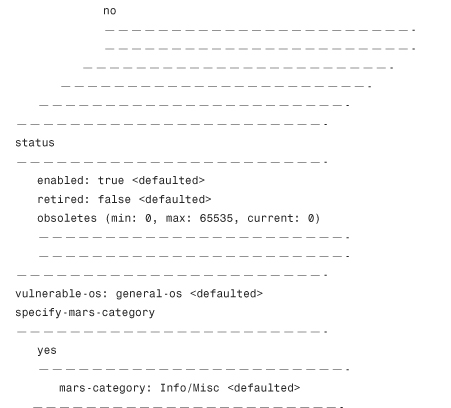
Step 5. To verify the settings, enter the show settings command under the signature definition submode for the new custom signature (60088):


Note
This process also applies to UDP and ICMP custom signatures. The parameters depend on the specific protocol services and ports.
IP Logging
The IP Logging feature enables the AIP-SSM to capture IP packet data if an attack or security threat is seen. This section demonstrates how to configure IP Logging to help perform deep analysis of a security threat on the network.
Note
IP Logging can affect performance on the AIP-SSM. You can limit the size of log files so that performance is not degraded. As an alternative, you may transfer the data to a dedicated management server.
The AIP-SSM can also be configured to capture all IP traffic from a specific host on the network. You can also specify the following:
• The duration during which the IP traffic should be logged
• The number of packets to be logged
• The maximum number of bytes to be logged
Note
The AIP-SSM stops logging packets if any of these parameters is met.
Automatic Logging
The goal in the following example is to configure the AIP-SSM to automatically log IP packets for attacker or victim traffic if a signature is triggered. The AIP-SSM logs the packets until any of the following criteria are met:
• No more than 250 packets
• No more than 300 seconds of logging
• No more than 81920 bytes of data
To accomplish this goal, complete the following steps:
Step 1. Log in to the AIP-SSM and enter into signature IP log configuration submode:

Step 2. Configure the AIP-SSM to only log 250 packets, using the ip-log-packets subcommand:
NewYorkSSM(config-sig-ip)# ip-log-packets 250
Step 3. Specify the duration during which you want the AIP-SSM to log packets:
NewYorkSSM(config-sig-ip)# ip-log-time 45
Step 4. Specify the number of bytes to be logged:
NewYorkSSM(config-sig-ip)# ip-log-bytes 81920
Step 5. Invoke the show settings command to verify the parameters entered:
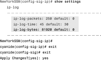
The shaded lines show the parameters entered and the default values.
Manual Logging of Specific Host Traffic
In the example illustrated in Figure 12-13, the goal is to capture all packets from a host with IP address 10.10.10.21. The security administrator was informed that other hosts in the network are seeing unusual packets from this host.
Figure 12-13 Manual Logging Example

The administrator uses the iplog command to configure manual IP Logging to log IP packets only from and to 10.10.10.21 during a three-minute period, as demonstrated in Example 12-22.
Example 12-22 Configuring Manual IP Logging

Notice the warning the AIP-SSM gives the administrator about the performance impact of the IP Logging feature.
The following is the iplog command syntax and all the available parameters:
iplog name ip-address [duration minutes] [packets numPackets] [bytes numBytes]
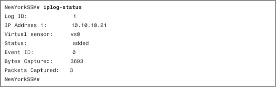
You can monitor the status of the packets logged by using the iplog-status command, as demonstrated in Example 12-23.
Example 12-23 IP Logging Status
To stop logging packets, use the no iplog command. This does not delete any captured packets from the system.
After capturing the respective IP packets, you can copy the IP log files to an FTP or SCP server. This enables you to examine those files with different sniffing tools, such as tcpdump or Wireshark. Use the copy iplog command to copy the IP log files. The following is the command syntax:
copy iplog log-id destination-url
In Example 12-24, the IP log file that was previously captured is copied to an FTP server with IP address 192.168.10.44.
Example 12-24 IP Logging Status
![]()
The IP Log ID displayed in the iplog-status command output is copied to the FTP server 192.168.10.44 and saved as a file named iplog1 by user1 (username on the FTP server).
Configuring Blocking (Shunning)
This section demonstrates how you can configure the AIP-SSM to interact with Cisco IOS routers, switches, PIX firewalls, and Cisco ASA appliances to block (shun) attacking IP addresses. It is important that you analyze your network topology to understand which attacking IP addresses should be blocked by the AIP-SSM and which IP addresses should never be blocked.
The AIP-SSM and other Cisco IPS sensors can interact with Cisco IOS routers and Catalyst switches. The AIP-SSM can apply ACLs in Cisco IOS routers or VACLs in Catalyst switches to permit or deny their interfaces or VLANs. The Cisco PIX Firewall does not use ACLs or VACLs; it uses the shun command to perform this operation.
You can configure the AIP-SSM to be able to block itself with the allow-sensor-block [true | false] command in the service network-access submode. However, this action is not recommended because it causes all packets sent and received by the blocking devices to be dropped.
In the example illustrated in Figure 12-14, the AIP-SSM is configured to interact with a Cisco IOS router (10.10.12.254) that provides extranet connectivity on a dedicated link to a partner connection.
Figure 12-14 Blocking (Shunning) Example

The following steps demonstrate how to configure the AIP-SSM:
Step 1. Configured a user profile called myprofile. Within this profile is stored the information that will be sent to the router for the AIP-SSM to be able to log in and manage it.

The username in this example is admin. You must also enter the router enable password.
Step 2. After configuring the user profile, enter the IP address of the router, as follows:
NewYorkSSM(config-net)# router-devices 10.10.12.254
Step 3. The previously configured user profile (myprofile) is associated to the NAC configuration:
NewYorkSSM(config-net-rou)# profile-name myprofile
Step 4. Specify the protocol the AIP-SSM is to use to communicate with the router:
NewYorkSSM(config-net-rou)# communication ssh-3des
SSH using the 3DES encryption algorithm is selected. You can use Telnet, SSH-DES, or SSH-3DES. The default is SSH-3DES.
Note
If you select DES or 3DES, you must add the router to the trusted SSH hosts in the AIP-SSM with the ssh host-key command.
Step 5. Optionally, you can specify the AIP-SSM NAT address (if the module is behind a NAT device) with the nat-address <nat_address> subcommand. NAT is not used in this example.
Step 6. Set the router’s interface name and direction in which the ACL will be applied (inbound or outbound):
NewYorkSSM(config-net-rou)# block-interfaces ethernet0 in
The ACL will be applied inbound to the ethernet0 interface on the router.
Step 7. Optionally, you can add a preblock ACL. This is generally used for permitting the traffic that the AIP-SSM should never block. A preblock ACL named preACL is configured in this example:
NewYorkSSM(config-net-rou-blo)# pre-acl-name preACL
Step 8. You can also (optionally) add a post-block ACL. This is mainly used to block or permit additional traffic on the same interface or direction.
NewYorkSSM(config-net-rou-blo)# post-acl-name postACL
Step 9. Exit service network access submode and apply the changes:

You can also configure the AIP-SSM to not block specific IP addresses or networks. In Example 12-25, the host with IP address 192.168.10.1 and the network 192.168.10.0/24 will never be blocked.
Example 12-25 Avoiding Blocking Critical Devices and Networks

To allow the AIP-SSM to save the router’s configuration after sending the respective commands, use the procedure demonstrated in Example 12-26.
Example 12-26 Enabling the AIP-SSM to Write Configuration to NVRAM

The default value of the maximum number of devices or networks that can be blocked in the AIP-SSM is 250. However, you can use the max-block-entries command, as demonstrated in Example 12-27, to set how many blocks are maintained simultaneously. The range is from 0 to 65535.
Example 12-27 Maximum Block Entries

The maximum number of block entries in Example 12-27 is 500.
Note
You should implement blocking/shunning very carefully because it can disrupt legitimate services within your network caused by false positives. This is why the tuning process is so important. Attackers can launch a DoS attack if they know about your shunning configuration. These DoS attacks can be orchestrated spoofing legitimate source addresses, consequently causing disruption of legitimate hosts and services.
Cisco Security Agent Integration
The Cisco Security Agent (CSA) solution provides numerous capabilities used to enforce security policies on end-user machines. This section covers the integration and configuration of CSA with the AIP-SSM.
The CSA solution has two components:
• Agents that reside on and protect endpoints
• Management Console (MC) used to manage the agents
The CSA agents send CSA MC host posture information based on the configured security policies. Subsequently, the CSA MC maintains a list of IP addresses that it has determined should be quarantined from the network. The CSA MC can be configured to send two types of events to the AIP-SSM or any Cisco IPS sensor:
• Host posture events
• Quarantined IP address events
Host posture events provide the following information:
• Unique host ID assigned by CSA MC
• CSA agent status
• Host system hostname
• Set of IP addresses enabled on the host
• CSA software version
• CSA polling status
• CSA test mode status
• NAC posture
Note
The host posture events are called imported OS identifications in IPS and AIP-SSM.
The quarantined host events provide the following information:
• IP address
• Reason for the quarantine
• Protocol associated with a rule violation (TCP, UDP, or ICMP)
• Indicator of whether a rule-based violation was associated with an established session or a UDP packet.
Note
The collection of quarantined host events is called the watch list in IPS and AIP-SSM.
SSL/TLS is used for communications between CSA MC and the AIP-SSM. The AIP-SSM initiates the SSL/TLS transactions with the CSA MC; however, this communication is mutually authenticated.
Note
The CSA MC must be added as a trusted host within the AIP-SSM. Instructions on how to add a trusted host in AIP-SSM were covered earlier in this chapter.
The following are several key points to remember when integrating CSA into the AIP-SSM:
• The AIP-SSM can store only a certain number of host records. If this number exceeds 10,000, subsequent records are dropped. If the 10,000 limit is reached and then the number drops to below 9900, new records are no longer dropped.
• Hosts can change an IP address because of DHCP lease expiration or movement in a wireless network and then appear as another host record. The AIP-SSM presumes the most recent host posture event to be the most accurate. IP address conflicts are also a known issue.
• A network can include overlapping IP address ranges in different VLANs, but host postures do not include VLAN ID information.
• The CSA MC event server allows up to ten open SDEE subscriptions by default; however, this value is configurable. On the other hand, you must have an administrative account to open SDEE subscriptions.
• The CSA data is not virtualized and is treated globally by the AIP-SSM.
Complete the following steps to configure the AIP-SSM to process CSA events:
Step 1. Log in to ASDM and navigate to Configuration > IPS > Sensor Management > External Product Interfaces.
Step 2. Click Add to add the CSA MC. The Add External Product Interface dialog box shown in Figure 12-15 is displayed.
Figure 12-15 Adding the CSA MC

Step 3. Enter the CSA MC IP address in the External Product’s IP Address field. The IP address of the CSA MC in this example is 192.168.10.155.
Step 4. Click the Enable Receipt of Information check box to enable the AIP-SSM to receive information from CSA MC.
Step 5. Enter the SDEE URL and port under the Communication Settings section. You must configure the URL based on the software version of the CSA MC with which the IPS is communicating as follows:
• CSA MC version 5.0 uses /csamc50/sdee-server.
• CSA MC version 5.1 uses /csamc51/sdee-server.
• CSA MC version 5.2 and higher uses /csamc/sdee-server (which is the default value).
Step 6. Enter the credentials required to log in to CSA MC under the Login Settings section.
Step 7. Click the Enable Receipt of Watch List check box to enable the receipt of the watch list information CSA MC.
Step 8. Enter the manual watch list risk rating (RR) in the Manual Watch List RR Increase field. The default value (25) is used in this example.
Step 9. The Session RR Increase field enables you to increase the percentage of the session-based watch list RR. The default value (25) is used in this example.
Step 10. The Packet RR Increase field enables you increase the percentage of the packet-based watch list RR. The default value (10) is used in this example.
Step 11. Click the Enable Receipt of Host Postures check box to enable the receipt of the host posture information.
Step 12. Check the Allow Unreachable Hosts’ Postures check box to allow the receipt of host posture information for hosts that are not reachable by the CSA MC.
Step 13. Enter the addresses of hosts that will be explicitly permitted or denied by clicking the Add button under the Permitted and Denied Host Posture Addresses section.
Step 14. Click OK.
To configure CSA MC to support IPS interfaces, follow these steps:
Step 1. Log in to the CSA MC and navigate to Events > Status Summary.
Step 2. In the Network Status section, click No beside Host History Collection Enabled, and then click Enable in the popup window.
Step 3. Navigate to Systems > Groups to create a new group (with no hosts) to use in conjunction with administrator account you will next create.
Step 4. Choose Maintenance > Administrators > Account Management to create a new CSA MC administrator account to provide IPS (AIP-SSM) access to the CSA MC system.
Step 5. Create a new administrator account with the role of Monitor.
Step 6. Choose Maintenance > Administrators > Access Control to further limit this administrator account.
Step 7. In the Access Control window, select the administrator you created and select the group you created.
Anomaly Detection
The Cisco IPS solution includes limited anomaly detection (AD) capabilities. The AD component of the AIP-SSM allows it to be less dependent on signature updates for protection against worms and scanners, such as Code Red, SQL Slammer, Conficker, and others. The AD component lets the AIP-SSM learn normal activity and send alerts or take dynamic response actions for behavior that deviates from what it has learned as normal behavior. This section covers the configuration of the AD component.
When the AIP-SSM is configured for AD, it initially conducts a learning process and then derives a set of policy thresholds that best fit the normal network. This initial learning mode is done for the default period of 24 hours. It is assumed that during this 24-hour period no attack is being carried out. AD creates an initial network traffic baseline, known as a knowledge base (KB).
Note
The default interval value for periodic schedule is 24 hours and the default action is rotate, meaning that a new KB is saved and loaded, and then replaces the initial KB after 24 hours.
After the learning mode, the AD should remain in “detect” mode for 24 hours a day, 7 days a week. AD goes into “inactive” mode when the AD feature is disabled in the AIP-SSM.
Complete the following steps to configure AD in the AIP-SSM when using ASDM:
Step 1. Log in to ASDM and navigate to Configuration > IPS > Policies > Anomaly Detection.
In the Anomaly Detections pane, you can add, clone, or delete an AD policy. The default AD policy is ad0. When you add a policy, a control transaction is sent to the sensor to create the new policy instance. In this example, the default AD policy is used.
Step 2. Select ad0. The screen shown in Figure 12-16 is displayed.
Figure 12-16 Configuring Anomaly Detection
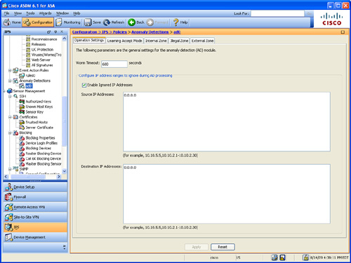
Step 3. On the Operation Settings tab, set the worm detection timeout in the Worm Timeout field. The range is 120 to 10,000,000 seconds. The default value of 600 seconds is used in this example. After this timeout, the scanner threshold returns to the configured value. You can also configure source and destination IP addresses that you want the sensor to ignore when AD is gathering information for a KB. AD does not track these source and destination IP addresses and the KB thresholds are not affected by these IP addresses.
Step 4. Configure IP address ranges to ignore during AD processing. Click the Enable Ignored IP Addresses check box to enable the list of ignored IP addresses entered in the Source IP Addresses and Destination IP Addresses fields respectively.
Step 5. Click the Learning Accept Mode tab to configure whether you want the sensor to create a new KB after a specified time interval. You can configure whether the KB is created and loaded (Rotate) or saved (Save Only). You can schedule how often and when the KB is loaded or saved.
Step 6. Click the Automatically Accept Learning Knowledge Base check box to enable the AIP-SSM to automatically update the KB.
Step 7. The Action pull-down menu enables you to specify whether to rotate or save the KB. If Save Only is selected, the new KB is created.
Step 8. The Schedule field enables you to choose Calendar Schedule or Periodic Schedule. Periodic Schedule option allows you to configure the first learning snapshot time of day and the interval of the subsequent snapshots. The default is the periodic schedule in 24-hour format. The Start Time option allows you to enter the time you want the new KB to start. The valid format is hh:mm:ss.
Step 9. Enter how long AD should be in learning mode under the Learning Interval field (in hours). The default value is 24 hours.
Step 10. Optionally, if you select Calendar Schedule, click Add under Times of Day and enter the times of day in the Add Start Time dialog box. Additionally, check the check boxes of the days of the week you want AD to be in learning mode under the Days of the Week section.
Step 11. AD uses the concept of network zones. A zone is a group of destination IP addresses. There are three zones: internal, illegal, and external. Each of these zones has its own threshold. Click the Internal Zone tab to configure the internal AD zone. The Internal Zone tab has four tabs:
• General—Used to enable the internal zone and specify its subnets.
• TCP Protocol—Used to enable TCP protocol and configure your own thresholds and histograms.
• UDP Protocol—Used to enable UDP protocol and configure your own thresholds and histograms.
• Other Protocols—Used to enable other protocols and your own thresholds and histograms.
Step 12. The illegal zone should represent IP address ranges that should never be seen in normal traffic. An example is unallocated IP addresses or part of your internal IP address range that is not being used. Click the Illegal Zone tab to configure the illegal AD zone. The Illegal Zone tab has four tabs that enable you to configure the same parameters as the ones in the Internal Zone:
• General—Used to enable the illegal zone and specify which subnets it contains.
• TCP Protocol—Used to enable TCP-based protocols and configure your own thresholds and histograms.
• UDP Protocol—Used to enable UDP-based protocols and configure your own thresholds and histograms.
• Other Protocols—Used to enable other protocols and your own thresholds and histograms.
Step 13. Click on the External Zone to configure the external AD zone. The External Zone tab has three other tabs:
• TCP Protocol—Used to enable TCP protocol and configure your own thresholds and histograms.
• UDP Protocol—Used to enable UDP protocol and configure your own thresholds and histograms.
• Other Protocols—Used to enable other protocols and your own thresholds and histograms.
Step 14. Click Apply to apply the configuration changes.
Step 15. Click Save to save the configuration.
The AIP-SSM Traffic Anomaly signature engine has nine AD signatures. Each signature has two sub-signatures: one for the scanner and the other for the worm-infected host. When an anomaly is detected, the AIP-SSM triggers an alert for these signatures.
Note
All the AD signatures are enabled by default. Additionally, their alert severity is set to high by default.
The following are the supported actions for AD signatures:
• Produce alert
• Deny attacker inline (if the AIP-SSM is configured in inline mode).
• Log attacker packets
• Deny attacker service pair inline
• Request SNMP trap
• Request block host
Cisco ASA Botnet Detection
Cisco ASA software release 8.2 introduced the Botnet Traffic Filter feature. This feature leverages IronPort technology to identify potential botnet traffic through the ASA. A botnet is a group of Internet robots (bots) that run malicious software often operated by different criminal entities. Although this is not an IPS feature, it is often referred to as an intrusion prevention feature. This section covers the configuration of the Cisco ASA Botnet Traffic Filter feature.
The Cisco ASA Botnet Traffic Filter feature has three major categories:
• Dynamic and Administrator Blacklist Data
The Botnet Traffic Filter feature does not automatically block botnet-related traffic. An administrator must manually configure ACLs to block malicious traffic.
Dynamic and Administrator Blacklist Data
The Cisco ASA Botnet Traffic Filter feature uses a dynamic database that is downloaded from an IronPort server accessible on the Internet. This database contains domain names and IP addresses for known malware and botnet sites. Complete the following steps to enable the Botnet Traffic Filter feature and configure the dynamic database and administrator black list data:
Step 1. Log in to ASDM and navigate to Configuration > Firewall > Botnet Traffic Filter > Botnet Database. The screen shown in Figure 12-17 is displayed.
Figure 12-17 Configuring the Botnet Database

Step 2. Check the Enable Botnet Updater Client check box to enable the Cisco ASA to fetch the latest database from the Cisco (Ironport) server.
Step 3. Check the Use Botnet Data Dynamically Downloaded from Updater Server check box to enable dynamic updates.
Step 4. The Fetch Botnet Database button is for testing purposes only. It is used to download and verify the dynamic database. However, it does not store the entries in running memory.
Step 5. To purge the botnet database, click the Purge Botnet Database button.
Step 6. Click Apply to apply the configuration changes.
You can also manually configure domain names or IP addresses to blacklist or whitelist. To configure a blacklist or whitelist, complete the following steps:
Step 1. Navigate to Configuration > Firewall > Botnet Traffic Filter > Black and White List pane. The screen shown in Figure 12-18 is displayed.
Figure 12-18 Configuring a Black and White List
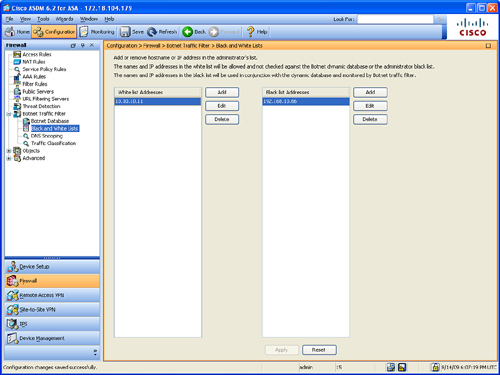
Step 2. Click Add for the Whitelist or Blacklist.
Step 3. Enter the hostname or the IP Address when the dialog box appears. In this example, the 10.10.10.11 host is added to the white list and the 192.168.10.66 host is added to the black list.
Tip
You can enter multiple entries separated by commas, spaces, lines, or semi-colons. Up to 1000 entries can be configured for each type.
DNS Snooping
When the Botnet Traffic Filter feature is enabled, the Cisco ASA compares DNS A-records and CNAME records against the domain names in the database. This is known as DNS snooping and is integrated with the current DNS inspection available on the ASA. When DNS snooping is enabled, the Cisco ASA builds a DNS reverse cache (DNSRC) for all the DNS replies received on interfaces where DNS snooping is enabled.
Complete the following steps to enable the DNS snooping:
Step 1. Navigate to Configuration > Firewall > Botnet Traffic Filter > DNS Snooping. The screen shown in Figure 12-19 is displayed.
Figure 12-19 Configuring DNS Snooping
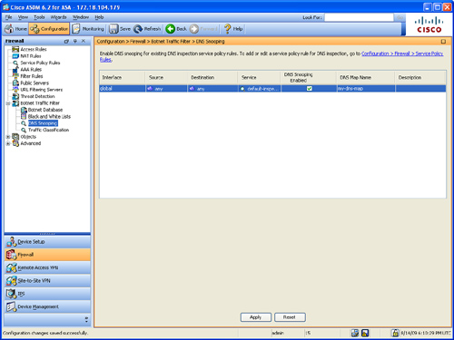
Step 2. Check the DNS Snooping Enabled check box to enable DNS snooping to an existing DNS inspection map. In this example, DNS snooping is enabled in the my-dns-map inspection map. Chapter 6, “Authentication, Authorization, and Accounting (AAA) Services” covers DNS inspection configuration in detail. The my-dns-map is the DNS inspection map configured in the example in Chapter 7. DNS snooping should be configured only on interfaces that are expected to receive external DNS queries.
Step 3. Click Apply to apply the configuration changes.
Traffic Classification
The Botnet Traffic Filter feature allows the administrator to configure different policies to specify what traffic will be inspected or “classified.” Additionally, it makes it possible to exclude certain interfaces to not inspect traffic for botnet activity. For instance, an administrator could enable traffic classification only on the outside interface because all other interfaces are trusted. When the Botnet Traffic Filtering feature is enabled, the Cisco ASA compares the source and destination addresses of traffic that is subject to the classification against the IP addresses that have been discovered for the various lists available.
Additionally, the Cisco ASA can log and report any related events. The Cisco ASA botnet traffic classification is done only for a connection received on the first interface where the feature is enabled. Complete the following steps to configure Traffic Classification and Reporting on the Cisco ASA:
Step 1. Navigate to Configuration > Firewall > Botnet Traffic Filter > Traffic Classification. The screen shown in Figure 12-20 is displayed.
Figure 12-20 Configuring Traffic Classification
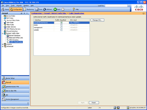
Step 2. Check the Traffic Classified check box for each interface on which Traffic Classification should be enabled. Alternatively, you can configure Traffic Classification globally, applying it to all interfaces, This is done by checking the Traffic Classified box for Global (All Interfaces), as shown in Figure 12-20.
Step 3. (Optional) You can add or edit access control lists (ACLs) to configure more granular parameters to specify what traffic should be classified. For instance, you can create an ACL to only inspect TCP port 80 from a specific network. To add or edit an ACL, click the Manage ACL option to bring up the ACL Manager and add the new ACL.
Step 4. Click Apply to apply the configuration changes.
Example 12-28 shows the equivalent CLI command for the previous ASDM configuration steps.
Example 12-28 Configuring Botnet Traffic Filter Through the CLI

Summary
Cisco ASA, in conjunction with the AIP-SSM modules, delivers a new generation of highly accurate and intelligent inline prevention services. This provides security administrators an Adaptive Threat Defense (ATD) across their business networks and applications. This chapter provided an overview of the Cisco IPS software architecture that runs in the AIP-SSM to provide IPS services. It included an introduction to the CLI, user administration, and maintenance tasks, and explained in depth advanced configuration tasks such as custom signatures, blocking, CSA integration, and anomaly detection. Additionally, the Cisco ASA Botnet Traffic Filter feature was covered in detail.