Chapter 3. Initial Setup and System Maintenance
Cisco Adaptive Security Appliance (ASA) can be set up in a number of ways to adapt to any network topology. However, proper planning is essential for successful implementations of the security features that Cisco ASA offers. This chapter guides you through the initial configuration of the security appliance and shows ways to monitor the system’s health and status.
Accessing the Cisco ASA Appliances
Cisco ASA provides two types of user interfaces:
• Command-line interface (CLI)—The CLI provides non-graphical access to the Cisco ASA. The CLI can be accessed from a console, Telnet, or Secure Shell (SSH) session. Telnet and SSH are discussed later in the chapter, under “Remote System Management.”
• Graphical user interface (GUI) via ASDM—Cisco Adaptive Security Device Manager (ASDM) provides an easy-to-navigate and simple graphical interface to set up and manage the different features that Cisco Adaptive Security Appliance (ASA) provides. It is bundled with a variety of administration and monitoring tools to check the health of the appliance and the traffic traversing through it. ASDM access requires IP connectivity between the ASDM client and the security appliance. If you have a new security appliance, you can assign the initial IP address via the CLI and then establish a GUI ASDM connection.
Establishing a Console Connection
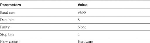
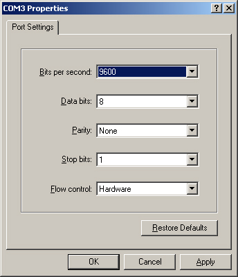
A new security appliance, by default, has no configuration and thus it does not have IP addresses assigned to any of its interfaces. To access the CLI, you need a successful connection to the console port of the security appliance. The console port is a serial asynchronous port with the settings listed in Table 3-1.
Table 3-1 Console Port Settings
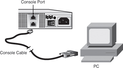
You can connect the console port on the security appliance to a serial port on a PC by using a flat rolled console cable, with a DB9 serial adapter on one end and a RJ-45 port on the other. The DB9 side of the cable goes to the serial port of a PC, and the RJ-45 end of the cable goes to the console port of the security appliance, as illustrated in Figure 3-1.
Figure 3-1 Console Port Connectivity from a Computer
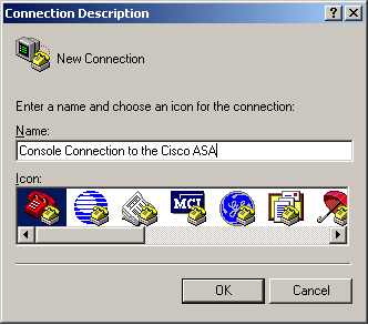
After connecting the console cable to the security appliance and the computer, launch terminal-emulation software, such as HyperTerminal or TeraTerm, to send and receive output. You can launch HyperTerminal by navigating to Start > Programs > Accessories > Communications > HyperTerminal on a Windows-based PC. The initial configuration window of HyperTerminal is shown in Figure 3-2. In the Connection Description dialog box, enter a connection name to identify this session as a unique connection. A connection name of Console Connection to the Cisco ASA is specified in Figure 3-2. You can choose an icon to associate with the connection entry. After filling out the connection name and selecting an icon, click OK to proceed.
Figure 3-2 Initial Configuration of HyperTerminal
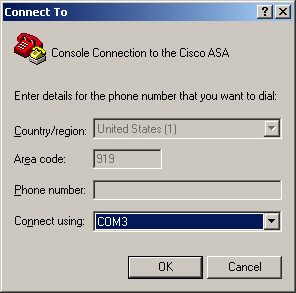
Specify the connection type in the Connect To window. Because the console port uses an asynchronous serial connection, the HyperTerminal setting must use a COM port. As illustrated in Figure 3-3, COM3 is being set up for the serial connection to the security appliance. After you are finished, click OK to proceed to the next configuration window.
Figure 3-3 Setting HyperTerminal Connection Type
The last window is used to configure port properties, such as the baud rate and flow control. Figure 3-4 shows HyperTerminal set up with the values listed in Table 3-1. After configuring the port settings, click OK to complete the configuration setup.
Figure 3-4 Setting HyperTerminal Port Specification
The HyperTerminal application is ready to transmit and receive data from the security appliance. If you press Enter a couple of times, you should see a ciscoasa> prompt in the HyperTerminal window.
The next section describes how to use the CLI after establishing a successful console connection.
Command-Line Interface
After a successful console connection, the security appliance is ready to accept your commands. The Cisco ASA contains a command set structure similar to that of a Cisco IOS router and offers the following access modes:
• User mode, also known as user access mode
• Privileged mode
• Configuration mode
• Sub-configuration mode
• ROMMON mode
User mode, shown as the hostname with a > sign, is the first mode of access available when you log in to the security appliance. This mode offers a limited set of commands that are useful in obtaining basic information about the security appliance. One of the important commands in this mode is enable, which prompts a user to specify a password to log in to privileged mode.
Privileged mode, shown as the hostname with a # sign, gives full access to a user after a successful logon. This mode also allows execution of all the commands that are available in user mode. The security appliance offers a rich set of monitoring and troubleshooting commands to check the health of different processes and features in the security appliance. One of the important commands in this mode is configure terminal, which places a user in configuration mode.
Note
The security appliance enables you to restrict the commands a user can run by implementing command authorization. This is covered in Chapter 6, “Authentication, Authorization, and Accounting (AAA) Services.”
Configuration mode, displayed as the host name with a (config)# prompt, allows a user to enable or disable a feature, set up security and networking components, and tweak the default parameters. This mode not only enables the user to configure the security appliance, but also allows the use of all the commands that are available in the user and privileged modes. A user may enter into the sub-configuration mode of different features from this mode.
Sub-configuration mode, displayed as the hostname with a (config-xx)# prompt, lets a user configure specific networking or security features on the security appliance. The xx is replaced by the process/feature keyword that is being configured on the security appliance. For example, if a user is setting up specific parameters on an interface, the prompt changes to (config-if)#. Sub-configuration mode enables the user to execute all the configuration mode commands as well as the user and privileged mode commands.
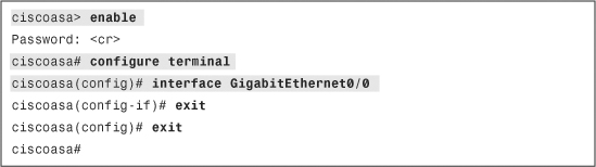
In Example 3-1, a user logs in to privileged mode from user access mode by typing the enable command. The security appliance prompts a user to specify a password to gain privileged mode access. If the security appliance has the default configuration, it uses a null (no) password to grant access. After logging in to privileged mode, the user types configure terminal to access configuration mode. The user enters into interface sub-configuration mode by typing the interface GigabitEthernet0/0 command. To go back to the previous mode, the user can enter exit or quit, as shown in Example 3-1.
Example 3-1 Accessing the Privileged and Configuration Modes
Tip
In the preceding example, the administrator of the security appliance typed exit twice to return to the privileged mode prompt. Optionally, you can type end to return to privileged mode from any configuration mode.
Like a Cisco IOS router, the security appliance also allows you to press the Tab key to complete a partial command. For example, to enter a show command, type sho and press the Tab key. The security appliance displays the complete show command on the screen.
The security appliance allows you to abbreviate commands and keywords to the number of characters that identify a distinct abbreviation. For example, you can abbreviate the enable command as en.
All the supported options and arguments of a command are displayed when you type ? after the command. For example, you can type show ? to see all the options that are supported under the show command.
The security appliance also provides a brief description and command syntax when you type help followed by the command. For example, when you type help reload, the security appliance shows the command syntax for reload, a description, and the supported arguments.
The security appliance uses ROMMON mode (Read-Only-Memory Monitor mode) when it does not find a bootable image or when an administrator forces it to enter into that mode. In ROMMON mode, you can use a TFTP server to load a system image into the security appliance. ROMMON mode is also used to recover the system password, discussed later in this chapter under “Image Recovery Using ROMMON.”
Managing Licenses
As mentioned in Chapter 2, “Cisco ASA Product and Solution Overview,” the security appliance controls the security and networking features through the use of a license key. You can obtain the information of the currently installed license key by issuing the show version command. This command also displays other system information, such as:
• The current version and the location of the system image
• The ASDM version, if installed
• The security appliance uptime
• The security appliance hardware model number, including the memory and flash information
• The physical interface and the associated IRQs (Interrupt Requests)
• The current features that are active on the security appliance
• The license information
• The security appliance’s serial number
• Configuration register setting
• Information about last configuration modification
Example 3-2 shows the output of show version, which has a VPN Plus–based license key installed.
Example 3-2 Output of show version
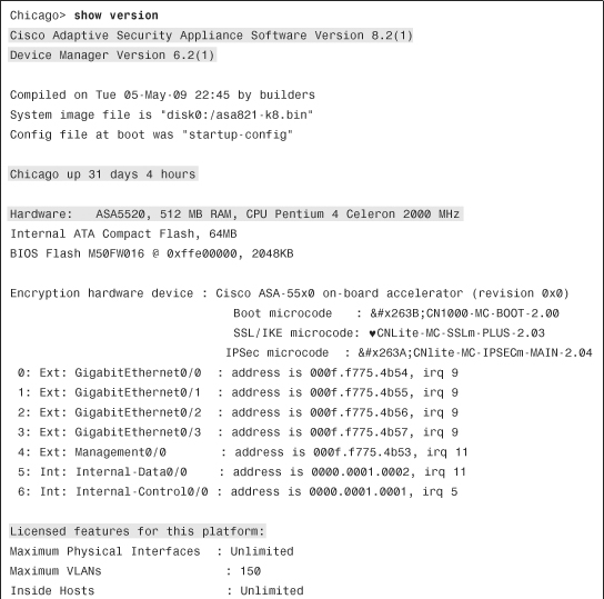
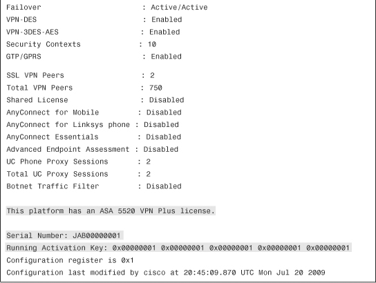
In Example 3-2, the security appliance is running a system image of 8.2(1) with the ASDM image of 6.2(1). The hardware model is ASA5520, running the Plus license. The serial number and the license activation key are masked to protect this system’s identity. The configuration register is set to 0x1, which instructs the security appliance to load the image from flash. The configuration register is discussed later in the “Password Recovery Process” section.
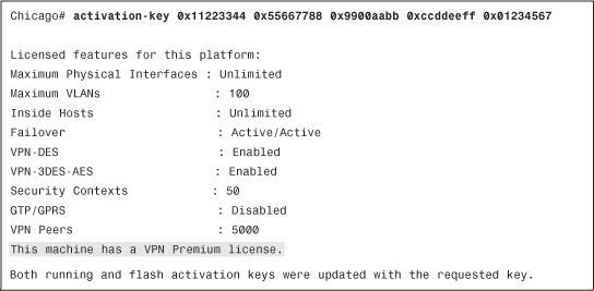
You can change the installed license key by using the activation-key command followed by the five-tuple key, as shown in Example 3-3. After the new activation key is entered, the security appliance shows the features set activated by the new license key. In this example, a VPN premium license key is installed.
Example 3-3 Changing the Activation Key
Note
Feature-specific activation keys are discussed in their respective chapters. For example, Chapter 19 discusses the license model for SSL VPN tunnels.
Initial Setup
If you are setting up a new security appliance, it must be configured from the CLI first. You cannot use ASDM until the security appliance is configured with the appropriate IP addresses and it has IP connectivity to ASDM client machine.
Initial Setup via CLI
When the security appliance is booted with no configuration, it offers a setup menu that enables you to configure the initial parameters such as the device name and the IP address. You can choose to go through the initial setup menu for quick configuration.
In Example 3-4, a security appliance prompts users to specify whether they wish to go through the interactive menu to preconfigure the device. If a user types no, the interactive menu is not shown and the security appliance shows the ciscoasa> prompt. If a user types yes, the default option, the security appliance walks the user through the configuration of ten parameters. The security appliance shows the default values in brackets ([]) before prompting the user to accept or change them. To accept the default input, press Enter. After going through the initial setup menu, the security appliance displays the summary of the new configuration before prompting the user to accept or reject it.
Example 3-4 Initial Setup Menu

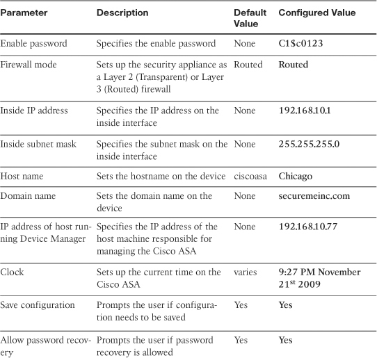
Table 3-2 lists all the parameters that can be configured in the initial setup menu. It also provides a brief description of each parameter, along with the default and configured values.
Table 3-2 Initial Setup Parameters and Their Values
You can define the initial parameters and features by using either the CLI commands or the ASDM. They are discussed throughout this chapter. The next section discusses how to configure a device name from the ASDM.
Tip
You can rerun the interactive setup process by using the setup command in configuration mode.
Initial Setup of ASDM
Before you can access the ASDM graphical console, you must install the ASDM software image on the local flash of the security appliance. The ASDM console can manage a local security appliance only. Therefore, if you need to manage multiple security appliances, the ASDM software must be installed on all the Cisco ASAs. However, a single workstation can launch multiple instances of ASDM clients to manage the different appliances. Optionally, you can leverage Cisco Security Manager (CSM) to configure multiple appliances simultaneously.
Note
This book focuses on setting up Cisco ASA through ASDM and the CLI. Configuring ASA through CSM is beyond the scope of this book.
Uploading ASDM
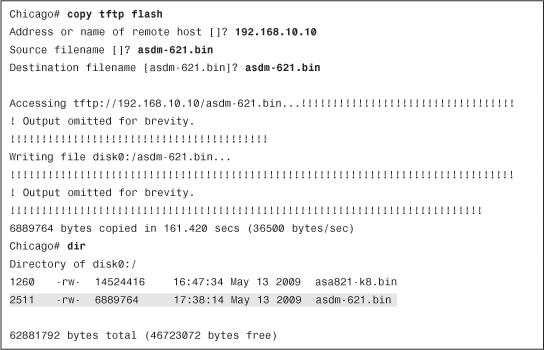
You can use the dir command to determine whether the ASDM software is installed. If the security appliance does not have the ASDM software, your first step is to upload the image from an external file server, using the one of the supported protocols. The appliance needs to be set up for basic configuration, such as the interface names, security levels, IP addresses, and proper routes, discussed later in this chapter. After setting up basic information, use the copy command to transfer the image file, as shown in Example 3-5, where an ASDM file, named asdm-621.bin, is being copied from a TFTP server located at 192.168.10.10. Verify the content of the local flash after the file is successfully uploaded. Copying images is discussed later in this chapter.
Example 3-5 Uploading the ASDM Image to the Local Flash
Setting Up the Appliance
When the ASDM file is accessed, the Cisco ASA loads the first ASDM image that it finds from the local flash. If multiple ASDM images exist in the flash, use the asdm image command and specify the location of the ASDM image you want to load. This ensures that the appliance always loads the specified image when ASDM is launched. In Example 3-6, the appliance is set up to use asdm-621.bin as the ASDM image file.
Example 3-6 Specifying the ASDM Location
![]()
The security appliance uses the Secure Socket Layer (SSL) protocol to communicate with the client. Consequently, the security appliance acts as a web server to process the requests from the clients. You must enable the web server on the appliance by using the http server enable command.
The security appliance discards the incoming requests until the ASDM client’s IP address is in the trusted network to access the HTTP engine. In Example 3-7, the administrator enables the HTTP engine and sets up the appliance to trust the 192.168.10.0/24 network connected toward the inside interface.
Example 3-7 Enabling the HTTP Server
![]()
Note
The SSL VPN implementation on the appliance also requires you to run the HTTP server on the appliance. Starting from version 8.0, you can set up the security appliance to terminate both the SSL VPN as well as the ASDM sessions on the same interface, using the default port of 443. Use https://<ASAipaddress>/admin to access the GUI for admin and management purposes. This is discussed in Chapter 19.
Accessing ASDM
ASDM’s interface can be accessed from any workstation whose IP address is in the trusted network list. Before you establish the secure connection to the appliance, verify that IP connectivity exists between the workstation and the Cisco ASA.
To establish an SSL connection, launch a browser and point the URL to the appliance’s IP address. In Figure 3-5, the administrator accesses ASDM by entering https://192.168.10.1/admin as the URL. The URL is redirected to https://192.168.10.1/admin/public/index.html.
Figure 3-5 Accessing the ASDM URL

Note
ASDM requires Sun Java plug-in 1.4(2), 1.5.0, or 6.0 installed on the web browser. The supported operating systems include Microsoft Windows Vista, 2003 Server, XP, 2000 Service Pack 4, Macintosh OS X, Red Hat Desktop, and Enterprise version 4.
The new security appliance presents its self-signed certificate to the workstation so that a secure connection can be established. If the certificate is accepted, the security appliance prompts the user to present authentication credentials. If the ASDM authentication or enable password is not set up, there is no default username or password. If enable password is defined, there is no default username and you must use enable password as the login password. If user authentication is enabled on the security appliance through use of the aaa authentication http console command, then those login credentials must be provided. After a successful user authentication, the appliance presents two ways to launch ASDM:
• Run ASDM as Java web start application—The security appliance launches ASDM in the client’s browser as a Java applet. This option is not feasible if a firewall that filters out Java applets exists between the client and the security appliance.
• Run ASDM as a local application—The security appliance offers a setup utility called asdm-launcher.msi, which can be saved to the workstation’s local hard drive.
Note
ASDM as a local application feature is currently supported on Windows-based operating systems.
When the ASDM application is launched, it prompts for the IP address of the security appliance to which you are trying to connect, as well as the user authentication credentials. Figure 3-6 illustrates this, where an SSL connection is being made to an appliance located at 192.168.10.1. If you have an enable password configured, specify it under Password and leave the Username blank to log in to ASDM.
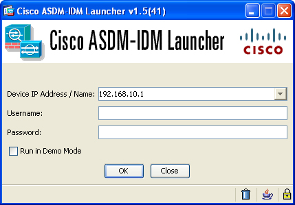
Note
If you are running version 8.2(1) on the security appliance, make sure that you use version 6.2(1) of ASDM. For more information about ASDM, consult http://www.cisco.com/go/asdm.
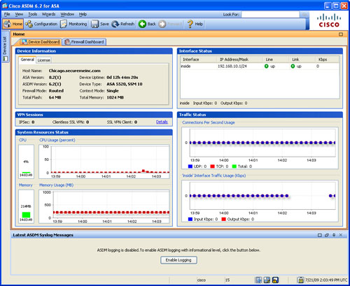
If the user authentication is successful, ASDM checks the current version of the installer application and downloads a new copy if necessary. It loads the current configuration from the security appliance and displays it in the GUI, as shown in Figure 3-7.
Figure 3-7 Initial ASDM Screen
Tip
ASDM logs debug and error messages into a file to troubleshoot any application-related issues. The name of the file is asdm-log-[timestamp].txt, and it is located at user_home_directory.asdmlog. For example, C:Documents and Settingsuser.asdmlog.
ASDM divides the initial screen, also known as the Home screen, into the following six sections:
• Device Information—Displays the hardware and software information of the security appliance, such as the current version of operating system and the device type. If the License tab is selected, ASDM shows the features that are enabled on the security appliance.
• VPN Sessions—Displays the number of active IPSec, clientless, and AnyConnect SSL VPN tunnels
• System Resources Status—Provides the current status of CPU and memory usage on the appliance.
• Interface Status—Displays the interface name and the assigned IP address. It also shows the link information of the currently configured interfaces and the rate of traffic passing through them.
• Traffic Status—Provides information about the number of active TCP and UDP connections and the traffic rate passing through the outside interface.
• Latest ASDM Syslog Messages—Shows the latest ASDM syslog messages that are generated by the security appliance. Syslogging is disabled by default and needs to be enabled for log monitoring. When enabled, the security appliance sends the messages to the ASDM client. This is discussed later in the chapter, in the “System Logging” section.
The statistics on the Home screen are refreshed every 10 seconds and show the information for the last 5 minutes.
ASDM shows three additional tabs on the home screen. They include
• Firewall Dashboard Tab—The Firewall Dashboard tab presents statistical information about the traffic passing through your security appliance. This includes the number of connections, NAT translations, dropped packets, attacks, and top usage statistics.
• Content Security Tab—The Content Security tab displays information about the Content Security and Control (CSC) SSM. This pane appears only if a CSC SSM is installed in the adaptive security appliance.
• IPS Tab—The Intrusion Prevention System tab displays information about the IPS module, if present.
Functional Screens of ASDM
In addition to the Home screen, the ASDM interface comes with the following two functional screens:
Configuration Screen
The Configuration screen is useful when the new or existing configuration needs to be modified. On the left side, it contains five to six features icons, depending on the hardware setup of the appliance, as shown in Figure 3-8.
Figure 3-8 Configuration Screen

The Feature icons of the Configuration screen are as follows:
• Device Setup—Configures interfaces and sub-interfaces on the security appliance. This panel is discussed in the section “Configuring an Interface,” later in the chapter.
• Firewall—Helpful in creating security policies to filter and to translate packets traversing through the appliance. Also enables you to define Failover, QoS, AAA, certificates, and many other firewall-related features.
• Remote Access VPN—Sets up the remote access VPN connections such as IPSec, L2TP over IPSec, Clientless SSL VPN, and AnyConnect tunnels.
• Site-to-site VPN—Sets up the site-to-site VPN tunnels.
• IPS—Sets up policies for the SSM card to monitor and drop unauthorized packets. This icon is not visible if an SSM card is not present.
• Device Management—Here, the basic device features can be set up. Most of these features are discussed later in this chapter. Helpful in setting up the basic software features, such as system logging and failover.
Monitoring Screen
The Monitoring screen displays statistics about the hardware and software features of the security appliance. ASDM provides real-time graphs to monitor the appliance’s health and status. Figure 3-9 shows the initial Monitoring screen.
Similar to the Configuration screen, the Monitoring screen also displays five or six icons, depending on whether or not you have the SSM module installed.
The Features icons of the Monitoring screen are described below:
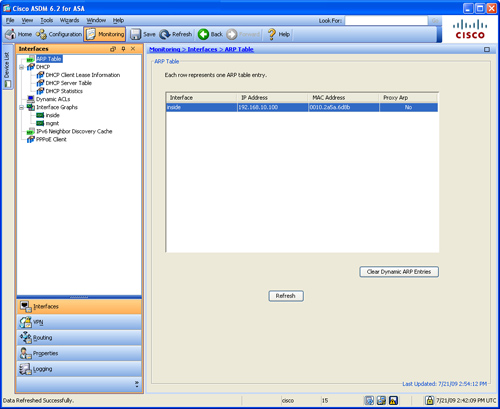
• Interfaces—Monitors interfaces and sub-interfaces by maintaining ARP, DHCP, and dynamic ACLs tables. It also provides a graphical representation of interface utilization and packet throughput.
• VPN—Monitors the active VPN connections on the security appliance. It provides graphs and statistical analysis of the site-to-site, IPSec, and SSL VPN–based remote-access tunnels.
• IPS—Provides statistical information for the packets going through the IPS engine. This icon is not present if the IPS module is not installed.
• Routing—Displays the current routing table and provides information on EIGRP and OSPF neighbors.
• Properties—Monitors active administrative sessions such as Telnet, SSH, and ASDM. It also provides graphical information about CPU, memory, and blocks utilization. Provides graphical information about the active translations and UDP/TCP connections. It provides graphical information of the IP audit, WCCP, CRL, and DNS Cache features
• Logging—Displays log messages as live events. It also shows log messages from the buffer space.
• Trend Micro Content Security—ASDM enables you to monitor the CSC SSM statistics, as well as CSC SSM-related features such as types of threats detected by the module, live event logs for real-time monitoring, and resource utilization graphs.
Note
If you use ASDM as the primary mode of configuring a security appliance, it is highly recommended that you enable the Preview Command Before Sending Them to the Device option in ASDM. This way, before the commands are pushed to the ASA, ASDM shows them to you for verification. You can enable this feature on ASDM under Tools > Preferences and selecting Preview commands before sending them to the device.
Device Setup
After you have connectivity to the security appliance, either via CLI or ASDM, you are ready to start configuring the device. This section guides you to configure the security appliance for basic setup.
Setting Up Device Name and Passwords
The default device name—also known as the hostname—of a security appliance is ciscoasa. It is highly recommended that you set a unique device name to identify the security appliance on the network. Additionally, networking devices usually belong to a network domain. A domain name appends the unqualified hostnames with the configured domain name. For example, if the security appliance tries to reach a host, secweb, by its hostname and the configured domain name on the security appliance is securemeinc.com, then the fully qualified domain name (FQDN) will be secweb.securemeinc.com.
In a new security appliance, you can configure the Telnet and enable password. The Telnet password is used to authenticate remote sessions either via the Telnet or SSH protocol, discussed later in this chapter. By default, the Telnet password is cisco. For the SSH sessions, the default username is pix. The enable password, on the other hand, gives you access to the privileged exec mode if you are on the user mode. The enable password is also used for ASDM user authentication. There is no enable password by default.
Note
If you have user authentication configured for Telnet and/or SSH access, the security appliance does not use the Telnet/enable passwords for those sessions.
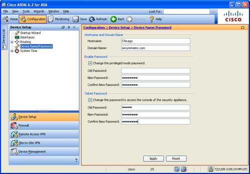
To configure the hostname, domain name, and the Telnet/enable passwords via ASDM, navigate to Configuration > Device Setup > Device Name/Password and specify the new settings. As shown in Figure 3-10, the hostname is Chicago and the domain name is securemeinc.com. If you want to configure a new Telnet and/or enable password, select the appropriate change the Telnet and/or enable password option and specify the current and the new passwords. In Figure 3-10, both passwords are set to C1$c0123 (masked).
Figure 3-10 Configuring Hostname, Domain Name, and Local Passwords
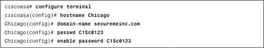
If you prefer to use the CLI, Example 3-8 shows the identical configuration of Figure 3-10. The hostname is changed using the hostname command, the domain name is changed using the domain-name command, and the Telnet and enable passwords are changed using the passwd and enable password commands, respectively.
Example 3-8 Setting Up the Hostname, Domain Name, and Passwords
Tip
If you view the configuration after adding the passwords, the security appliance displays the encrypted passwords as follows:
Chicago# show running-config | include pass
enable password 9jNfZuG3TC5tCVH0 encrypted
passwd 2KFQnbNIdI.2KYOU encrypted
Configuring an Interface
Cisco ASA 5500 appliances come with a number of Fast-Ethernet, Gigabit-Ethernet and Ten Gigabit-Ethernet interfaces. They also include one management interface (Management0/0) in all one-rack unit (1RU) models and two management interfaces (Management0/0 and Management0/1) in ASA5580s. Additionally, you can create one or more sub-interfaces off each physical interface. The Fast-Ethernet, Gigabit-Ethernet, and Ten Gigabit-Ethernet interfaces are used to route traffic from one interface to another based on the configured policies, whereas the management interface is designed to establish out-of-band connections.
Configuring Data-Passing Interface
Cisco ASA protects the internal network from external threats. Each interface is assigned a name to designate its role on the network. The most secure network is typically labeled as the inside network, whereas the least secure network is tagged as the outside network. For semi-trusted networks, you can define them as demilitarized zones (DMZs) or any logical interface name. You must use the interface name to set up the configuration features that are linked to an interface.
Note
If you go through the initial setup and configure an IP address and a subnet mask, the security appliance designates the GigabitEthernet0/1 interface as the inside interface on the Cisco ASA 5520, 5540, and 5550, and it designates Ethernet0/1 as the inside interface on the Cisco ASA 5510. By default, all these interfaces are shut down, meaning no traffic can pass through them.
The security appliance also uses the concept of assigning security levels to the interfaces. The higher the security level, the more secure an interface is. Consequently, the security level is used to reflect the level of trust of this interface with respect to the level of trust of another interface on the Cisco ASA. The security level can be between 0 and 100. Therefore, the most secure network is placed behind the interface with a security level of 100, whereas the least secure network is placed behind an interface with a security level of 0. A DMZ interface can be assigned a security level between 0 and 100.
The Cisco ASA enables you to assign the same security level to more than one interface. If communication is required between the hosts on interfaces at the same security level, use the global configuration same-security-traffic permit inter-interface command. Additionally, if an interface is not assigned a security level, it does not respond back at the network layer.
Note
When an interface is configured with a nameif command, the security appliance automatically assigns a preconfigured security level. If an interface is configured with the inside name, the security appliance assigns a security level of 100. For all the other interface names, the security appliance sets the security level to 0.
The most important parameter under the interface configuration is the assignment of an IP address. This is required if an interface is to be used to pass traffic in the Layer 3 firewall, also known as routed mode. An address can be either statically or dynamically assigned. For a static IP address, configure an IP address and its respective subnet mask.
The security appliance also supports interface address assignment through a Dynamic Host Configuration Protocol (DHCP) server and via PPPoE. Assigning an address via DHCP is a preferred method if an ISP dynamically allocates an IP address to the outside interface. You can also inform the security appliance to use the DHCP server’s specified default gateway as the default route if the “Obtain default route using DHCP” option is enabled on ASDM.
Note
If a security appliance is deployed in transparent mode, as discussed in Chapter 9, “Transparent Firewalls,” the IP address is configured in global configuration mode.
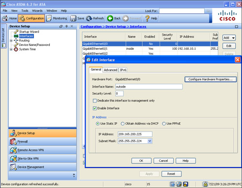
To configure a physical interface on a security appliance via ASDM, navigate to Configuration > Device Setup > Interfaces, select an interface, and click the Edit button. As shown in Figure 3-11, the physical GigabitEthernet0/0 interface is configured as the outside interface with a security level of 0. The static IP address is 209.165.200.225 with a mask of 255.255.255.224. The Enable Interface box is checked to activate the interface.
Figure 3-11 Configuring a Physical Interface with an IP Address
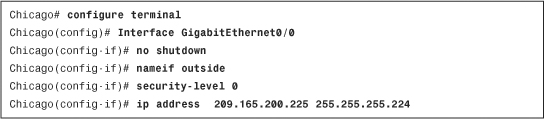
In Example 3-9, the administrator enables the GigabitEthernet0/0 interface as the outside interface and assigns a security level of 0. The IP address is 209.165.200.225 with a mask of 255.255.255.224.
Example 3-9 Enabling an Interface
ASDM enables you to configure speed, duplex, and media-type on an interface if you click an interface’s Configure Hardware Properties. By default, the speed and duplex are set to auto and can be changed to avoid link negotiations. If the speed and duplex settings do not match the speed and duplex settings on the other end of the Ethernet connection, you see packet loss, which results in performance degradation. The media-type is either RJ45 for copper-based interfaces or SFP for fiber-based interfaces. RJ45 is the default media-type.
Tip
The Ethernet-based interfaces on the Cisco ASA 5500 series use the auto-MDI/MDIX (media-dependent interface/media-dependent interface crossover) feature, which does not require a crossover cable when connecting interfaces of two similar types. They perform an internal crossover when a straight network cable connects two similar interfaces. This feature works only when both the speed and duplex parameters are set to auto-negotiate.
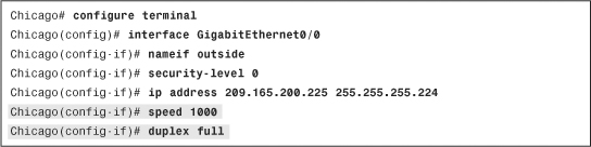
As demonstrated in Example 3-10, the outside interface is set up with a connection speed of 1000 Mbps, using full-duplex mode.
Example 3-10 Configuring Speed and Duplex on an Interface
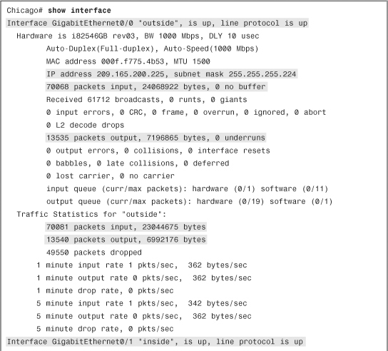
The security appliance shows the output of interface-related statistics when you issue the show interface command from the CLI. As illustrated in Example 3-11, GigabitEthernet0/0 is set up as the outside interface and has an IP address of 209.165.200.225, whereas GigabitEthernet0/1 is set up as the inside interface with an IP address of 192.168.10.1. This command also shows the packet rate and the total number of packets entering and leaving the interface.
Example 3-11 Output of show interface

Configuring a Subinterface
Cisco ASA has a limited number of Ethernet-based interfaces, depending on the platform you are using. However, you can divide a physical interface into multiple logical interfaces to increase the total number of interfaces. You do so by tagging each subinterface with a unique virtual LAN (VLAN) ID, which keeps the network traffic separate from other VLANs using the same physical interface. The security appliance uses the IEEE-specified 802.1Q trunking to connect the physical interface to an 802.1Q-enabled device.
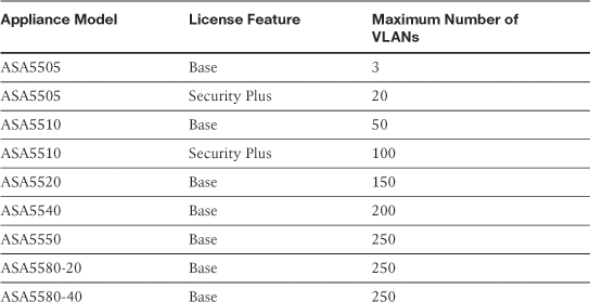
The number of VLANs (subinterfaces) can range from 3 to 250 depending on the security appliance model and the license key used, as shown in Table 3-3. VLAN ID must be between 1 and 4094, whereas the subinterface must be an integer between 1 and 4,294,967,295. Although the subinterface number and the VLAN ID do not have to match, it is a good practice to use the same number for ease of management.
Table 3-3 Supported Subinterfaces on the Security Appliances
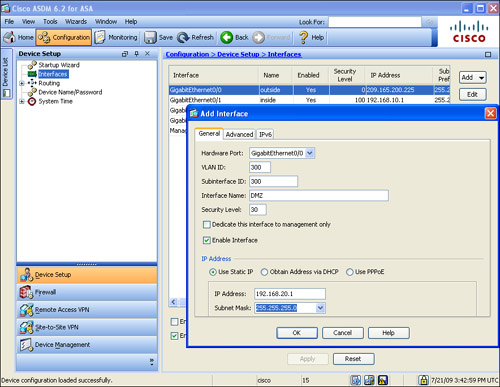
To create subinterfaces via ASDM, you can go to Configuration > Device Setup > Interfaces, select a physical interface, and click the Add button. As shown in Figure 3-12, the administrator is creating a sub-interface from a physical GigabitEthernet0/0 interface. The sub-interface number is 300 and it is linked to VLAN 300. A static IP address of 192.168.20.1/24 is configured for this sub-interface.
Figure 3-12 Configuring a Subinterface
Example 3-12 demonstrates how to create a subinterface 300 off GigabitEthernet0/0. It is linked to VLAN 300 and configured with an IP address of 192.168.20.1/24.
Example 3-12 Creating a Subinterface

Note
If the main physical interface is shut down, all the associated subinterfaces are disabled as well.
Even if you create subinterfaces, a security appliance can still pass untagged traffic over the physical interface if an interface name (nameif), a security-level, and an IP address are configured.
Configuring a Management Interface
All Cisco 1 RU security appliances have one built-in Management0/0 port, whereas the 5580 appliances have two built-in Management0/0 and Management0/1 interfaces. These interfaces are designed to pass management-related traffic only. The management interface blocks all the traffic that is trying to pass through it, and permits only traffic destined to the security appliance. This ensures that the management traffic is separate from the data traffic on an appliance. Any Gigabit Ethernet or Fast Ethernet interface can act as a dedicated management interface when Dedicate this interface for management only option is configured within ASDM or the management-only command is issued from the CLI. Some general characteristics about management interfaces include the following:
• Routing protocols such as RIP and OSPF are supported on a management interface.
• A subinterface can also act as a management interface if configured to do so.
• Multiple management interfaces are supported on an appliance.
• Traffic through the security appliance is dropped on a management interface and a syslog message is generated to log this event.
• VPN tunnels for remote management are allowed to terminate on a management interface.
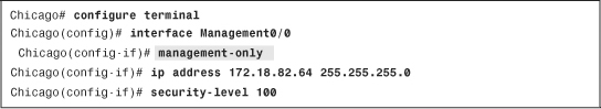
As shown in Example 3-13, the Management0/0 interface is set up as a management-only interface with an IP address of 172.18.82.64/24 and a security level of 100.
Example 3-13 Configuring a Management-Only Interface
You can change this default behavior of Management0/0 interface so that it can start passing through-traffic if you use the no management-only interface command.
DHCP Services
Cisco ASA can act as a DHCP server to distribute IP addresses to the end machines that are running DHCP client services. This feature is particularly important if you have a small branch office that does not own a dedicated DHCP server. To configure the DHCP server via ASDM, go to Configuration > Device Management > DHCP > DHCP Server and select the interface where you want to enable the DHCP services. ASDM opens a new window where you can define the following attributes:
• Enable DHCP Server—The first thing in setting up the DHCP server is to enable it on the selected interface by selecting the Enable DHCP Server check box.
• DHCP Address Pool—You must define a pool of addresses that can be assigned to a DHCP client. Specify a start and an end address for the DHCP pool. The network addresses need to be on the same network as the address assigned to the interface.
• Optional Parameters—Cisco ASA enables you to set up a number of useful DHCP parameters such as the WINS and DNS addresses, domain-name, lease length, and the ping timeouts. The DHCP server sends the WINS, DNS, and domain name when an address is offered to a DHCP client. The client computers do not need to be manually set up for these addresses. If the ping timeout is configured, the security appliance sends two ICMP request packets to the address it is about to assign, before it allocates the IP address to a DHCP client. It waits for 50 milliseconds to receive an ICMP response. If a response is received, the security appliance assumes that the address is being used and thus does not assign it. If a response is not received, the security appliance allocates the IP address until the DHCP lease expires. After the lease expires, the DHCP client is expected to return the assigned IP address. You can change the default lease time setting of 3600 seconds by specifying a value in the Lease Length box.
• Enable Auto-Configuration from Interface—In many network implementations, the security appliance acts as a DHCP client on one interface and a DHCP server on another. This is usually the case when the security appliance gets an IP address from the ISP’s DHCP server on its outside interface. At the same time, it acts as a DHCP server to assign addresses to the DHCP clients connected on the inside networks. In this network scenario, the security appliance can pass the DNS, WINS, and domain-name information to the DHCP clients after it receives those attributes from a DHCP server that resides on its interface acting as a DHCP client. You enable this feature by selecting the Enable Auto-Configuration from Interface box and specifying a DHCP client–enabled interface such as the outside.
• Advanced—The security appliance enables you to assign DHCP option codes ranging from 0 to 255. These DHCP option codes are defined in RFC 2132 and can be set up on the security appliance if you click the Advanced option. For example, the DHCP option code 66 (TFTP server) is assigned to the DHCP clients with a TFTP server address. This DHCP option code is typically used by the Cisco IP Phones to retrieve their configuration from the TFTP server.
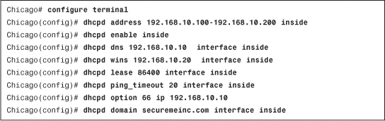
In Figure 3-13, a DHCP server is enabled on the inside interface with a pool of addresses that starts at 192.168.10.100 and ends at 192.168.10.200. The optional parameters are configured where the DNS address of 192.168.10.10, WINS address of 192.168.10.20, and a domain name of securemeinc.com are sent to the DHCP clients. The ICMP ping timeout is set to 20 milliseconds and the lease time of 86400 seconds (1 day) is defined. The DHCP auto-configuration is not enabled.
Figure 3-13 Configuring DHCP Service on the Security Appliance

Example 3-14 shows that DHCP service is enabled for the inside interface with the address range from 192.168.10.100 to 192.168.10.200. The assigned DNS and WINS addresses are 192.168.10.10 and 192.168.10.20 respectively. A DHCP option code 66 (TFTP server) is assigned to the DHCP clients, with a TFTP server address of 192.168.10.10.
Example 3-14 Configuring DHCP Service on the Inside Interface
IP Version 6
IP version 6 (IPv6) is a relatively new IP protocol developed to fix the shortcomings of the current IPv4 implementations. When IPv4 was standardized in 1981, the current challenges were not anticipated. The challenges include
• Exponential growth of Internet usage
• Scalability of large routing tables on the Internet backbone routers.
• Supportability of real-time data delivery
IPv6 not only fixes these problems but also provides improvements to IPv4 in areas such as IP security and network auto-configuration.
With the increased use of IP-enabled wireless phones and PDAs, the IPv4 address space is running out. Although network techniques such as Network Address Translation (NAT) and short-term DHCP leases have helped to conserve these addresses, more and more home users are demanding always-on Internet connections.
To accommodate the growing global demand for IP addresses, the new IPv6 implementation quadruples the number of bits used in an IPv4 address-from 32 bits to 128 bits. It provides 2128 routable IP addresses, enough to assign over a thousand IP addresses per person on this planet.
IPv6 Header
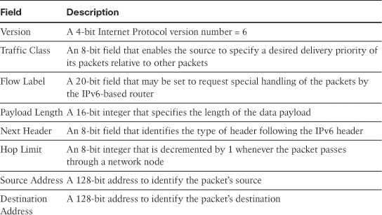
IPv6 specifications, defined in RFC 2460, describe an IPv6 header, as shown in Figure 3-14.
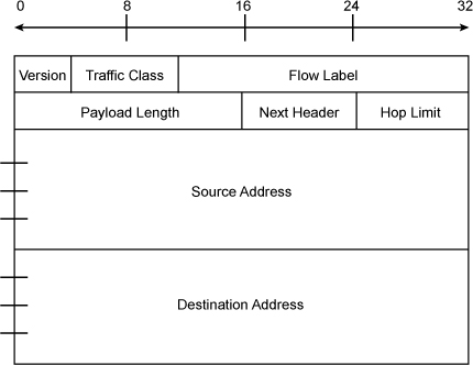
Table 3-4 lists and describes the fields in an IPv6 header.
In the case of IPv4, an IP address is represented in four octets, separated by dots (.). To accommodate a 128-bit IPv6 address, the address is divided into eight blocks of 16 bits each, separated by colons (:). Consequently, this representation is referred to as colon-hexadecimal notation.
The following are a few examples of IPv6 addresses:
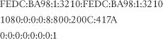
FEDC:BA98:0001:3210:FEDC:BA98:0001:3210
1080:0000:0000:0000:0008:0800:200C:417A
0000:0000:0000:0000:0000:0000:0000:0001
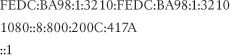
In an IPv6 address, it is not required to write the leading zeros in the individual block, as in an IPv4 address. Thus the preceding addresses can be rewritten as follows:
As you can see from the preceding addresses, an IPv6 address may have long strings of zero bits. For ease of representation, an IPv6 address with long sequences of zeros can be compressed and replaced with ::. This notation, also known as double colon, can compress contiguous blocks of zeros. However, the :: notation can appear only once in an address, to avoid confusion on how many zeros should go to which instance of ::. The preceding addresses, with zero compression, can be written as follows:
Configuring IPv6
The security appliance supports a number of IPv6 features, which include IP address assignment, packet filtering, basic routing using static routes, neighbor discovery, limited remote-access VPNs, and IPv6-supported application inspections such as FTP, HTTP, and SMTP. This section discusses IP address assignment, whereas packet filtering and basic routing using static routes are discussed in Chapter 4 and Chapter 5 respectively. In version 8.2(1) or higher, the security appliance supports the intrusion prevention system (IPS) and transparent firewall features.
IP Address Assignment
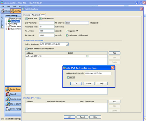
The security appliance supports simultaneous IPv4 and IPv6 addresses on an interface. You can configure an IPv6 address on an interface by navigating to Configuration > Device Setup > Interfaces, selecting an interface, clicking the Edit button, and then selecting the IPv6 tab, as shown in Figure 3-15.
Figure 3-15 IPv6 Address Assignment
The security appliance supports four types of interface address assignments:
• Auto-configuration address
Note
For detailed information about these types, consult RFC 4291.
Global Unicast Address
A global unicast IPv6 address, similar to an IPv4 public routable address, is used for Internet connectivity. It uses a prefix of 2000::/3 and requires a 64-bit interface identifier in the extended universal identifier 64 (EUI-64) format.
Each physical interface has an embedded 48-bit MAC address that specifies a unique link-layer address. You can derive the EUI-64 format interface ID from the interface MAC address by using the following rules:
• Insert FFFE between the upper and the lower 24 bits. For example, if the interface’s MAC address is 000F.F775.4B57, the modified address will be 000F.F7FF.FE75.4B57.
• Change the 7th bit in the leftmost byte to 1. For example, if the 64-bit address is 000F.F7FF.FE75.4B57 (derived in the previous step), after the 7th bit is changed the new address becomes 020F.F7FF.FE75.4B57. This new address is in the EUI-64 format.
The earlier Figure 3-15 shows how to set up a global unicast IPv6 address of 2001:1ae2:123f with a mask of /48 followed by the EUI-64 format identifier to make up the full 128-bit address.
Site-Local Address
A site-local IPv6 address, similar to an IPv4 private address, is used for the hosts on the trusted networks that do not require Internet connectivity. It uses a prefix range of FEC0::/10 and uses the EUI-64 format interface ID for a complete IPv6 address. The use of site-local addresses is deprecated by RFC 3879. Therefore, the configuration of a private IPv6 addresses should be done based on the recommendations of unique local addressing in RFC 4193.
Link-Local Address
A link-local IPv6 address allows IPv6-enabled hosts to communicate with each other by using the neighbor discovery protocol without needing to configure a global or site-local address. The neighbor discovery protocol provides a messaging channel on which the neighbor IPv6 devices can interact. It uses a prefix of FE80::/10 and the EUI-64–format interface ID as the complete link-local address. The link-local address is auto-assigned to an interface when IPv6 is enabled. To manually assign a different link-local address, configure an IPv6 address in the Link-local address option. As shown in Figure 3-15, where an IPv6 address of fe80::20f:f7ff:fe75:4b58 is being assigned.
The security appliance enables you to assign a link-local address on the interface if you select the Enable addresss autoconfiguration option. The security appliance listens for the Router Advertisement (RA) messages to determine the prefix and generates an IPv6 address by using the EUI-64–format interface ID.
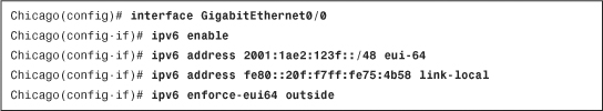
Example 3-15 shows complete IPv6 interface configuration on the outside interface, where a global address of 2001:1ae2:123f::/48 and a link-local address of fe80::20f:f7ff:fe75:4b58 are configured.
Example 3-15 Assigning IPv6 Addresses
Note
The current implementation of IPv6 on the security appliances does not support anycast addresses.
Optional IPv6 Parameters
The security appliance supports a number of IPv6 optional parameters that are configured under the IPv6 tab of an interface, as shown earlier in Figure 3-15. These parameters are discussed in the following sections.
Neighbor Solicitation Messages
These messages are sent to perform duplicate address detection. By default, the security appliance sends one duplicate address detection message on an IPv6-enabled interface. The security appliance sends Neighbor Solicitation messages only when it needs to do neighbor discovery. You can change this behavior by specifying a new value under the DAD Attempts option. If you specify a value of 0, the security appliance disables duplicate address detection on the interface.
If you configure an interface to send out more than one duplicate address detection message, you can also specify the interval at which the neighbor solicitation messages are sent out. The security appliance sends out one message every second. You can change this behavior by specifying a new value under the NS Interval option.
Neighbor Reachable Time
The neighbor reachable time is the amount of time, in milliseconds, that a remote IPv6 node is considered reachable. The security appliance can detect the unavailable neighbors in an IPv6 network by using the neighbor reachable time. If you define short reachable times, the security appliance can quickly detect unavailable neighbors. However, it adds bandwidth and processing overhead on the IPv6-enabled devices, and thus configuring short reachable time is not recommended in a typical IPV6 network. You can change this behavior by specifying a new value under the Reachable Time option. The default value of 0 indicates that the reachable time is sent as undetermined. It is up to the receiving devices to set and track the reachable time value.
Router Advertisement Transmission Interval
A security appliance can send router advertisements to an all-nodes multicast address so that neighboring devices can dynamically learn a default router address. The security appliance includes the router lifetime value to indicate its usefulness as the default router on the network. You can change the router lifetime from its default interval time of 1800 seconds by specifying a new value under the RA Lifetime box.
Router advertisement messages use ICMPv6 Type 134 and are periodically sent out to all the IPv6-enabled interfaces. If you would rather change the router advertisement interval from its default value of 200 seconds to something different, specify a new value in the RA Interval box. The transmission interval must be less than or equal to the IPv6 router advertisement lifetime.
Lastly, you can configure the security appliance to suppress router advertisement messages so that the security appliance does not provide its IPv6 prefix on an interface, such as an untrusted interface. You can do that by enabling the Suppress RA option.
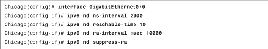
Example 3-16 shows the GigabitEthernet0/0 is set up for a neighbor solicitation messages interval of 2000 milliseconds, a neighbor reachable time of 10 milliseconds, and a router lifetime value of 10000 milliseconds. The security appliance is also set up to suppress router advertisement messages on the interface.
Example 3-16 Setting Up Optional IPv6 Parameters
Setting Up the System Clock
One of the most important tasks when setting up the security appliance is to verify that the clock settings are accurate. The security appliances can use the system clock to timestamp the syslog messages before sending them, as discussed in the “Enabling Logging” section. The system clock is also checked when the VPN tunnels, using PKI, are being negotiated to verify the validity of the certificate presented by the VPN peer. The security appliance supports two methods to adjust the system clock:
• Automatic clock adjustment using the Network Time Protocol
Manual Clock Adjustment
Similar to a Cisco IOS router, the security appliance allows the use of the clock set command to adjust the system clock. After setting the clock, the security appliance updates the system BIOS, powered by a battery on the motherboard. Consequently, if the security appliance is rebooted, the time setting does not need to be reconfigured. To manually adjust the system clock using ASDM, navigate to Configuration > Device Setup > System Time > Clock and specify a time zone, date, and the current time.
Time Zone
Cisco ASA supports displaying the system time in the correct time zone. It maintains the system clock in Universal Time, Coordinated (UTC), but shows it in the configured time zone. As shown in Figure 3-16, the configured time zone is Eastern Standard Time (EST), which is 5 hours behind UTC time. The security appliance automatically displays the system clock in the correct daylight savings time (DST).
Figure 3-16 Adjusting System Clock Manually

Note
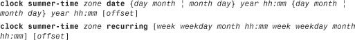
Even though the ASDM automatically adjusts the system clock for DST, you can manually override the DST setting using one of the two formats:
• Using specific date and time settings
• Using recurring date and time settings
The command syntax for both formats is as follows:
For example, you can set a policy to always start DST at 5 a.m. on the first Sunday of April and end it at 5 a.m. on the last Sunday of October, as follows:
Chicago(config)# clock summer-time CDT recurring 1 Sun Apr 5:00 last Sun Oct 5:00
Date
Cisco ASDM presents a drop-down calendar where you can select the current date. The calendar year is a four-digit number ranging between 1993 and 2035. In Figure 3-16, the current date is October 22, 2009.
Time
Cisco ASDM allows you to specify time in hours, minutes, and seconds, using the 24-hour time format.
Example 3-17 shows the clock on the security appliance is updated to use the current time of 11:36:50 and the current date of October 22, 2009. The current time zone is CST, where DST starts on the second Sunday in March and ends on the first Sunday in November.
Example 3-17 Setting the System Clock and Time Zone

Automatic Clock Adjustment Using the Network Time Protocol
Cisco ASA provides support for the Network Time Protocol (NTP) to synchronize the system clock with an NTP server. The device administrator does not need to update the system clock manually because the security appliance overrides the manual clock setting when it synchronizes the time with the NTP server. Setting up an NTP server is important when an organization uses certificates (PKI) to authenticate users and devices on the network.
To set up NTP, navigate to Configuration > Device Setup > System Time > NTP > Add and specify the attributes discussed in Table 3-5.
Table 3-5 NTP Arguments and Description

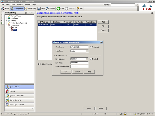
Figure 3-17 illustrates two NTP servers located on the inside interface. The server at 192.168.10.16 is a trusted and preferred server, whereas the server at 192.168.10.15 is the secondary NTP server. Both servers use an authentication key of 919919. They require an MD5 authentication key of cisco123 to successfully authenticate the security appliance.
Figure 3-17 Adjusting System Clock Automatically via NTP
Example 3-18 shows the equivalent configuration of Figure 3-17 via the CLI.
Example 3-18 Configuration of NTP Server

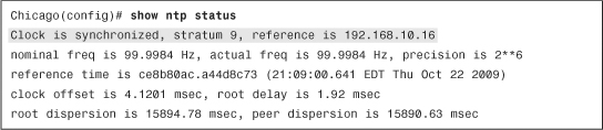
To verify whether the system clock is synchronized with the NTP server, use the show ntp status command, as shown in Example 3-19.
Example 3-19 Output of show ntp status
Configuration Management
The security appliance keeps two copies of the configuration in the system:
• The active, or running, configuration
• The saved, or startup, configuration
These configurations, as well as how to remove configurations from the security appliance, are discussed in the following subsections.
Running Configuration
The running configuration is the actual configuration that the security appliance loads in its memory. When the security appliance boots up, it copies the saved configuration in its memory and then uses it to function as configured. Use the show running-config or write terminal command to display the current configuration that the security appliance is using. These are the most important commands to verify that the security appliance is configured properly. The running configuration is not saved in nonvolatile RAM (NVRAM) until the security appliance is instructed to store it there.
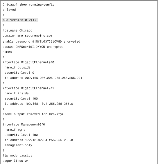
Example 3-20 shows the current configuration on an appliance via the CLI. As you can see, the configuration file can be fairly large and complex, depending on the number of features configured on the security appliance. The configuration file displays the current version of the system image and then the rest of the configuration parameters. If you prefer to see the same configuration via ASDM, click File > Show Running Configuration in New Window. ASDM launches a new default browser window to show the running configuration.
Example 3-20 Output of show running-config

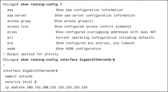
Cisco ASA allows you to display specific parts of the configuration by using show running-config, followed by the name of the command you are interested in checking. As shown in Example 3-21, the show running-config ? command shows all possible keywords you can use, and the show running-config interface gigabitEthernet0/0 command shows the running configuration of the GigabitEthernet0/0 interface.
Example 3-21 Partial Output of show running-config
Tip
The show running-config command does not display all security appliance commands set to their default values. Use show running-config all to display the entire running configuration.
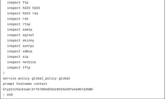
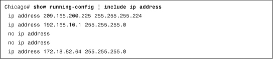
The Cisco ASA operating system enables you to enhance the search capabilities when a show command is executed, by using | grep at the end of the command. Alternatively, | include displays the output when the exact phrase matches a show command. You can also use | exclude command to exclude lines that match a particular phrase. In Example 3-22, the administrator is only interested in looking at the IP addresses set up on the security appliance and their respective subnet masks in the running configuration.
Example 3-22 Selective Output of show running-config
The security appliance can also display the selective output of a show command when the | begin option is used. In this case, the security appliance displays the output beginning from a specific keyword. As shown in Example 3-23, the administrator is interested in looking at the running configuration beginning from the physical interfaces. Use the show running-config | begin interface command to do this.
Example 3-23 Output of show running-config Beginning from the Interface Configuration

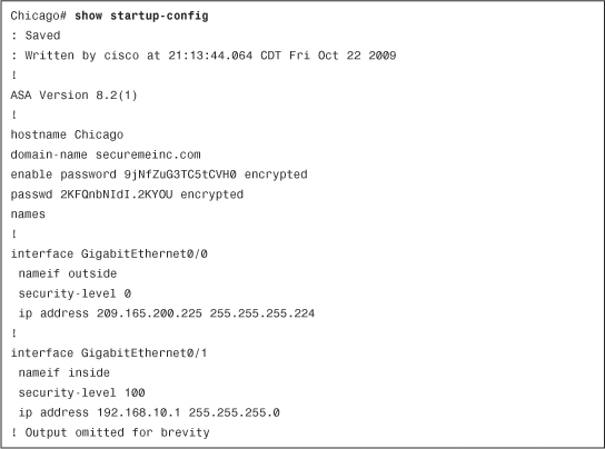
Startup Configuration
During the bootup process, the security appliance uses the saved configuration as the running configuration. This saved configuration is known as the startup configuration. You can view the startup configuration by using the show startup-config or show configuration command, as shown in Example 3-24.
Example 3-24 Output of show startup-config
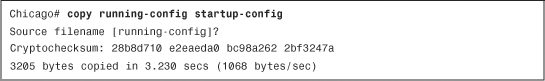
The output of show running-config and show startup-config may or may not be identical, depending on whether the two configurations were synced. Use the copy running-config startup-config or write memory command to copy the active configuration into NVRAM, as shown in Example 3-25.
Example 3-25 Output of copy running-config startup-config
Using ASDM, save the running-configuration as startup-configuration by clicking File > Save Running Configuration to Flash.
Removing the Device Configuration
If you use ASDM, you can remove any configured feature by selecting that feature and deleting it or changing the values to their defaults. For example, if you created a subinterface on the Gigabit-Ethernet0/0, you can remove that subinterface by selecting it and then clicking the Delete button.
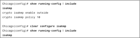
Using the CLI, you can remove a configured command from the configuration by using the no form of the command. This undoes the command that was previously entered into the configuration. In Example 3-26, the security appliance is set up for ISAKMP processing on the outside interface. It is being disabled with the no isakmp enable outside command.
Example 3-26 Disabling ISAKMP Processing on the Outside Interface
![]()
The security appliance can also remove the current configuration for a specific feature if the clear configure command is used. If the security appliance is set up with an ISAKMP policy 10 for Phase 1 IPsec negotiations, the clear configure isakmp command removes all the isakmp commands from the running configuration. This is demonstrated in Example 3-27.
Example 3-27 Clearing All ISAKMP Commands from the Running Configuration
Note
The use of no in a command removes a single line, whereas clear configure removes the parts of the configuration for a feature.
The preceding example not only cleared the ISAKMP policy, but also removed the crypto isakmp enable outside command from the running configuration. Use the clear configure crypto isakmp policy command to remove only the ISAKMP policy from the active configuration.
Unlike a Cisco IOS router, the Cisco ASA can clear the running configuration without going through the reboot process. This is helpful in a scenario where the security appliance needs to be put in the default configuration. Use the clear configure all command to clear the running configuration, as shown in Example 3-28.
Example 3-28 Clearing the Running Configuration
![]()
Warning
The use of clear configure all command disconnects your connection if your connection to the security appliance uses a remote-management protocol such as SSH. Make sure that you are connected to the ASA via console before you issue this command.
With ASDM, you can also clear the entire configuration of a security appliance by clicking File > Reset Device to the Factory Default Configuration. ASDM prompts you to configure an IP address on the management interface. You can reestablish your ASDM connection to this IP address.
The security appliance can also erase the startup configuration from NVRAM if the write erase command is issued from privileged mode, as shown in Example 3-29.
Example 3-29 Clearing the Startup Configuration
![]()
Tip
Cisco ASDM allows you to back up the configuration, certificates, XML files, SSL VPN customized files, and CSD/AnyConnect images. You can restore them in a different security appliance if you are configuring both appliances identically. Navigate to Tools > Backup Configuration to start the backup process.
Remote System Management
You do not have to be physically connected to the console port of the security appliance to access the CLI. The security appliance supports three remote-management protocols:
• Telnet
As mentioned earlier, we discuss ASDM throughout this book. The other remote system management protocols are discussed next.
Telnet
Cisco ASA comes with a Telnet server that enables users to manage it remotely via the CLI. The default behavior of the security appliance is to deny Telnet access from all clients unless they are explicitly permitted.
Note
The communication between a client and the security appliance is not encrypted; therefore, it is highly recommended to use SSH rather than Telnet for remote device management.
You may choose to enable Telnet on all interfaces. However, the security appliance does not allow clear-text Telnet communication on the outside interface unless the session is protected by an IPSec tunnel. The security appliance requires a user to establish an IPSec tunnel to the outside interface to encrypt the traffic destined to the security appliance. After the tunnel is successfully negotiated, the user can start a Telnet session to the outside interface.
When a Telnet client tries to connect, the security appliance verifies the following two conditions:
• The client’s IP address falls in the allowed address space.
• The interface that is receiving the request is allowed to accept requests from the client’s address space.
If either one of the conditions is not valid, the security appliance simply drops the request and generates a syslog message for this incident. Syslogs are discussed later in this chapter.
An external authentication server, such as CiscoSecure Access Control Server (ACS), can be used to authenticate the Telnet sessions. Consult Chapter 6, “Authentication, Authorization, and Accounting (AAA) Services” for more information.
You can configure the security appliance to accept Telnet sessions on an interface by navigating to Configuration > Device Management > Management Access > ASDM/HTTPS/Telnet/SSH and clicking Add. ASDM prompts you to select the following:
• Interface name from which the Telnet clients will be coming.
• IP Address of the hosts or a network address that is allowed to connect to the selected interface.
• Mask of the allowed IP or subnet address.
In Figure 3-18, the management network, 172.18.82.0/24, is allowed to establish Telnet sessions to the security appliance’s mgmt interface.
Figure 3-18 Telnet Services for the Management Network

Example 3-30 shows the relevant configuration for this setup. If the Telnet connection is idle, the security appliance is set up to time it out after 5 minutes, which is the default timeout.
Example 3-30 Configuration of Telnet Access on the Management Interface

If a user is allowed to connect, the security appliance goes through the user authentication phase and prompts the user for login credentials. The default Telnet password to gain user access mode is cisco. Consult the “Setting Up Device Name and Passwords” section earlier in the chapter to learn how to change the Telnet password.
Note
It is highly recommended that you change the default password of the security appliance to avoid unauthorized access.
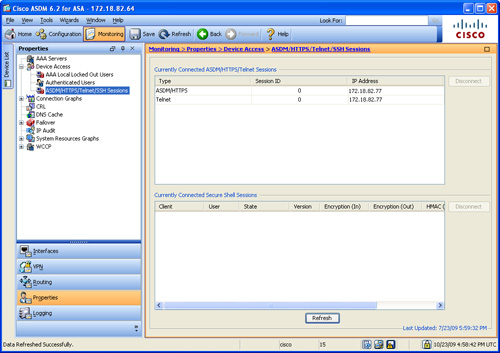
If the authentication is successful, the security appliance grants user access–mode CLI to the authenticated user. You can monitor the active Telnet sessions by going to Monitoring > Properties > Device Access > ASDM/HTTPS/Telnet/SSH Sessions. This displays the Telnet connection ID along with the client’s IP address. You can use the connection ID to clear out a session if you believe that it should not be established. You do so by selecting the user and clicking the disconnect button.
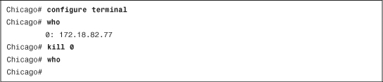
In Figure 3-19, the security appliance has assigned a connection ID of 0 to a Telnet client 172.18.82.77. An ASDM session is also established from the same client IP address.
Figure 3-19 Monitoring Remote Management Sessions
Example 3-31 shows the relevant configuration for this setup. A Telnet session is built from 172.18.82.77. This connection is being disconnected by use of the kill command.
Example 3-31 Monitoring and Clearing Active Telnet Sessions
Secure Shell (SSH)
SSH is the recommended way to connect to the security appliance for remote management because the data packets are encrypted by industry-standard algorithms such as 3DES and AES. The SSH implementation on the security appliance supports both version 1 and 2.
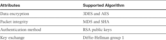
Before the SSH client and the Cisco ASA SSH server encrypt data, they go through an exchange of RSA security keys. These keys are used to ensure that an unauthorized user cannot look at the packet content. When a client tries to connect, the security appliance presents its public keys to the client. After receiving the keys, the client generates a random key and encrypts it, using the public key sent by the security appliance. These encrypted client keys are sent to the security appliance, which decodes them using its own private keys. This completes the key exchange phase, and the security appliance starts the user authentication phase. Cisco ASA supports a number of security algorithms, listed in Table 3-6.
Table 3-6 Security Algorithms Supported by Cisco ASA
To configure SSH on the security appliance, follow these steps:
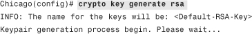
Step 1. Generate the RSA keys.
The SSH daemon on the security appliance uses the RSA keys to encrypt the sessions. You generate the public and private key pair by going to Configuration > Device Management > Certificate Management > Identity Certificates > Add > Add a New Identity Certificate and selecting New for Key Pair. Alternatively, you can use the crypto key generate rsa command from the CLI as shown in the following output. For detailed information about generating the RSA keys, consult Chapter 18, “Public Key Infrastructure (PKI).”
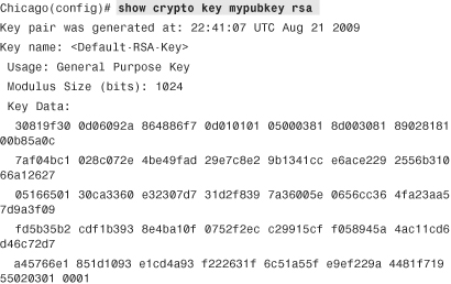
You can change the default modulus size, 1024 bits, to 512, 768, or 2048 bits. After the keys have been generated, you can view the public keys by using the show crypto key mypubkey rsa command:
Step 2. Enable SSH on an interface.
You can configure the security appliance to accept SSH sessions on an interface by navigating to Configuration > Device Management > Management Access > ASDM/HTTPS/Telnet/SSH and clicking Add. ASDM prompts you to select an interface name and specify the IP address/mask, similar to what was covered in the Telnet section. As shown in the following example, the security appliance is configured to accept SSH sessions from the mgmt network, 172.18.82.0/24:
Chicago(config)# ssh 172.18.82.0 255.255.255.0 mgmt
Note
Unlike Telnet, Cisco ASA enables you to terminate SSH sessions on the outside interface. SSH sessions are already encrypted and do not require an IPSec tunnel.
After a client negotiates the security parameters, the security appliance prompts the user for authentication credentials. If the authentication is successful, the user is put into user access mode.
Note
If AAA settings or local user accounts are not used, the default username is pix and the password is cisco.
Step 3. Restrict the SSH version.
The security appliance can restrict a user to use either SSH version 1 (SSHv1) or SSH version 2 (SSHv2) when a connection is made. By default, the security appliance accepts both versions. SSHv2 is the recommended version because of its strong authentication and encryption capabilities. However, the security appliance does not provide support for the following SSHv2 features:
• X11 forwarding
• Port forwarding
• Secure File Transfer Protocol (SFTP) support
• Kerberos and AFS ticket passing
• Data compression
In ASDM, select the SSH version from the Allowed SSH Version(s) drop-down menu, as shown in Figure 3-18. To set a specific SSH version via CLI, use the ssh version command, followed by the actual version of the shell.
Note
The security appliance must have the 3DES-AES feature set in the license to support SSHv2 sessions.
Step 4. Modify the idle timeout (optional).
Similar to the Telnet timeout, you can fine-tune the idle timeout value between 1 and 60 minutes. If the organizational security policy does not allow long idle connections, the idle timeout value can be changed to a lower value, such as 3 minutes, from its default value of 5 minutes.
Step 5. Monitor the SSH sessions.
As with Telnet sessions, you can monitor the SSH session by going to Monitoring > Properties > Device Access > ASDM/HTTPS/Telnet/SSH Sessions. This displays useful information such as the username, IP address of the client, encryption and hashing used, the current state of the connection, and the SSH version that is used. You can also use the show ssh session command from the CLI to get similar information.
If you like to manually disconnect an active SSH session, click the Disconnect button. CLI admins can issue the ssh disconnect command followed by the session ID number.
Step 6. Enable secure copy (SCP).
You can use the SCP file transfer protocol to move files to the network device securely. It functions similarly to FTP but with the added advantage of data encryption. The security appliance can act as an SCP server to allow SSHv2 clients to copy files in Flash. SCP can be enabled by navigating to Configuration > Device Management > Management Access > File Access > Secure Copy (SCP) Server and selecting Enable Secure Copy Server. If you prefer to use the CLI, use the ssh scopy enable command as follows:
Chicago(config)# ssh scopy enable
Note
The SSH client must be SCP capable to be able to transfer files.
System Maintenance
This section explains how to manage and install a different system image file on the Cisco ASA and ways to recover a device with no operating system. This section also discusses how to recover authentication passwords if they are lost.
Software Installation
Cisco ASA supports upgrading a system image file to flash via both the Cisco ASDM and the Cisco ASA CLI.
In case the security appliance does not have a bootable image, this section also discusses steps to upload the image from ROMMON.
Image Upgrade via the Cisco ASDM
ASDM can upload either an ASA or an ASDM image to the Cisco ASA flash with the HTTPS protocol if you click Tools > Software Updates. ASDM gives you two options:
• Upload a file from the local computer to the local flash of Cisco ASA.
• Check Cisco’s website for the latest version of the ASA bootable image.
In most cases, you want to download a bootable image from Cisco.com to your local workstation. Many enterprises want to test an ASA image in their lab environment first to make sure that the new image fits their requirements.
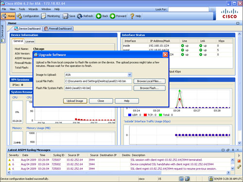
If you choose Upgrade Software from Local Computer, select whether you want to upload an ASDM or an ASA image, and then specify the path to the image file on the local drive. For ease of use, you can also click Browse Local Files and select the file by browsing the local hard-drive file structure. Specify the destination location on the Cisco ASA flash and then click Upload Image to initiate the file transfer process, as shown in Figure 3-20.
Figure 3-20 Upgrading Image Through ASDM
If the system Flash contains more than one system image, the security Cisco ASA boots off from the first image it finds in Flash. If the image you want to boot is not the first one on the disk, you should set the boot order to load the desired binary image file. Navigate to Configuration > Device Administration > System Image/Configuration > Boot Image/Configuration > Add > Browse Flash and select the image from which you want to boot. If you have selected multiple images to boot from, you can change the priority of a particular image by clicking the Move Up and Move Down buttons.
After a new image has been uploaded, you must reboot the appliance to load the new image. You do so by clicking Tools > System Reload. Cisco ASDM prompts to ask whether you want to save the running configuration in the NVRAM and whether you want to reload now or schedule a time to reboot later.
Image Upgrade via the Cisco ASA CLI
The security appliance supports a number of file server types, including TFTP, HTTP(s), and FTP, to download a system image into flash (disk0). The image upgrade process uses the copy command followed by the name of the file transfer type. The copy command copies the specified files from the source location or URL to the destination location (flash). The destination location of the system image is the local file system. The security appliance has an internal storage disk, referred to as disk0: or flash. Additionally, an external storage device, referred to as disk1:, can be used to save system images.
You can also use the noconfirm option to notify the security appliance to accept the parameters without prompting the user for confirmation. This is useful if customized scripts are used to upload system images.
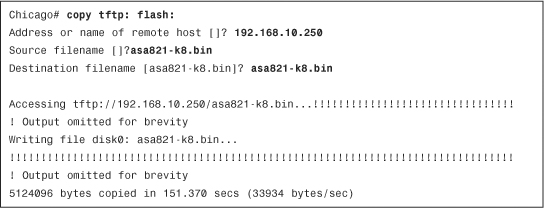
Example 3-32 illustrates how to configure the security appliance to download an image file, called asa821-k8.bin, from a TFTP server located at 192.168.10.250. The security appliance initiates the download process and stores the image file as asa821-k8.bin.
Example 3-32 Copying a System Image from a TFTP Server to the Local Flash
Example 3-33 illustrates how to configure the security appliance to download an image file, called asa821-k8.bin, from an FTP server located at 192.168.10.251. The username is Cisco and the password is cisco123.
Example 3-33 Copying a System Image from a FTP Server to the Local Flash

You can verify that the downloaded image file was successfully saved in flash by typing the dir command, as demonstrated in Example 3-34.
Example 3-34 Output of the dir flash Command

As mentioned earlier, the security appliance allows multiple system image files to reside in flash. If rebooted, the security appliance loads the first available system image. You can modify this default behavior by using the boot system command to ensure that the newly uploaded image file is used for bootup. This is shown in Example 3-35, where the security appliance is set up to boot from asa821-k8.bin.
Example 3-35 Setting the Boot Parameter
![]()
After configuring the Cisco ASA to boot a specific image upon bootup, the running configuration needs to be saved to NVRAM, as shown in Example 3-36.
Example 3-36 Copy Running-Config to NVRAM
![]()
To reboot the security appliance, you can use the reload command, as shown in Example 3-37. The security appliance shuts down all the processes and reloads itself. Based on the boot system parameters, it loads the asa821-k8.bin image.
Example 3-37 Reloading the Security Appliance

Note
Before you reload the security appliance, schedule a maintenance window to avoid disrupting production traffic.
The last step in verifying that the security appliance is running the desired version of code is to issue the show version command, as shown in Example 3-38.
Example 3-38 Output of show version
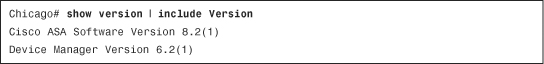
Image Recovery Using ROMMON
The security appliance provides a way to recover the system image in case the file is lost or gets corrupted and the security appliance ends up in ROMMON mode. If the security appliance is actively running an image file, you can upload a new image in flash by using the guidelines described previously in the “Software Installation” section. However, if an image file is not present and the security appliance is reloaded, ROMMON mode can be invoked to upload an image using the TFTP protocol. You must complete this process through the CLI.
Before an image can be uploaded, verify that the TFTP server hosts the file in the root directory and that network connectivity exists between the security appliance and the TFTP server. Assign an IP address to the security appliance by using the address command, and configure a TFTP server by using the server command. You can map the configured IP address to an interface by using the interface command followed by the physical interface name. The file command can be used to set the name of the system image file. Example 3-39 assigns an IP address of 192.168.10.1 to the GigabitEthernet0/1 interface. The TFTP server is 192.168.10.250 and the name of the system image file is asa821-k8.bin.
Example 3-39 Setting Up TFTP Parameters
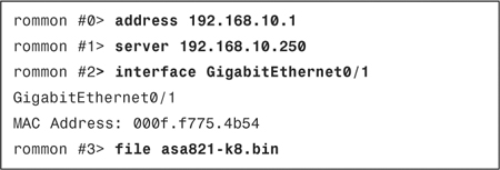
Note
If the security appliance and the TFTP server reside on different IP subnets, then you must define a default gateway on the security appliance by using the gateway command:
rommon #2> gateway 192.168.10.100
To verify whether all the attributes are properly configured, use the set command, as shown in Example 3-40. Start the TFTP process by issuing the tftpdnld command.
Example 3-40 Verifying the TFTP Parameters
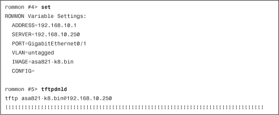
Note
The security appliance downloads the system image file in memory and boots up the device. However, the downloaded system image is not stored in Flash. Follow the guidelines described previously in the section “Image Upgrade via the Cisco ASA CLI” to upload the image in the system flash.
Password Recovery Process
The password recovery process on a security appliance is used when the system password is either locked out due to configured authentication parameters or lost. This process for Cisco ASA is similar to the password recovery process for an IOS router, which uses ROMMON mode to recover. You should schedule a maintenance window in which to recover the system passwords, because this process will require you to reboot the security appliance. Use the following steps for password recovery:
Step 1. Establish a console connection.
This process requires you to have physical access to the security appliance, for security reasons. This is to ensure that remote or unauthorized users cannot reset passwords. Consequently, a console connection to the security appliance is required. Consult the “Establishing a Console Connection” section earlier in the chapter.
Step 2. Reload the security appliance.
You start the password recovery process by turning the security appliance off and then turning it back on. This is necessary when you do not have the password to reboot the appliance from the CLI.
Step 3. Break into ROMMON.
When the security appliance starts to reboot, the startup messages are displayed on the console. Press the Esc (Escape) key after Use BREAK or ESC to interrupt boot is shown. This takes you into ROMMON mode, as follows:
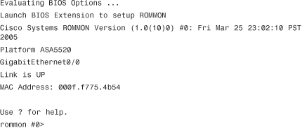
Step 4. Set the ROMMON configuration register.
ROMMON mode includes the confreg command, which sets the configuration register responsible for changing the security appliance boot behavior. It can be used to specify how an appliance should boot (ROMMON, NetBoot, and Flash boot) or if it should ignore the default configuration during bootup. When the confreg command is entered, the security appliance displays the current configuration register value and prompts the user for several options. Record the current configuration register value and press y to enter interactive mode:
The security appliance prompts the user for new values to be assigned to the configuration register. Select all the default values until the system prompts the user to disable system configuration. Enter y as shown in the following configuration:
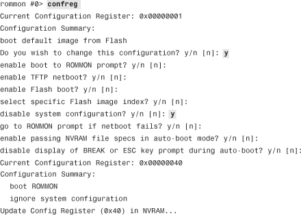
Step 5. Boot up the security appliance.
After setting up the configuration register to ignore the configuration file, boot the security appliance by using the boot command:
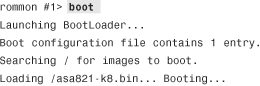
Step 6. Access privileged mode.
The security appliance loads the default configuration, which does not use an enable password to access privileged mode. After the security appliance shows the default ciscoasa prompt, type the enable command to gain privileged mode access:
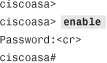
Step 7. Load the saved configuration.
After you have privileged mode access to the security appliance CLI, load the saved configuration from NVRAM. You do so by using the copy command, which copies the startup-config file to the running-config as follows:
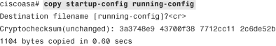
Step 8. Reset the passwords.
After loading the saved configuration, change the login, enable, and user passwords. The login password is used to get user mode access, and the enable password is used to gain privileged-mode access. In the following example, login and enable passwords are changed to C1$c0123:
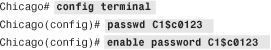
If the security appliance is using local user authentication, the user passwords can also be changed, as shown here for user cisco:
Chicago(config)# username cisco password C1$c0123
Step 9. Restore the original configuration register value.
To ensure that the security appliance does not ignore the saved configuration in the next reboot, you must change the configuration register value to reflect this. Restore the original configuration register value of 0x1 by using the config-register configuration-mode command:
Chicago(config)# config-register 0x1
Step 10. Save the current configuration into NVRAM.
Make sure that the newly specified passwords are stored in the saved NVRAM configuration. You do so by using the copy command to copy the running-config file in NVRAM as the startup-config, as follows:
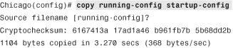
Note
The write memory command copies the running-config file into NVRAM as startup-config.
Disabling the Password Recovery Process
Cisco ASA can disable the password recovery process discussed in the previous section to enhance device security. This ensures that even if an unauthorized user gets access to the console port, that user should not be able to compromise the device or configuration settings. Use the no service password-recovery command to disable password recovery from configuration mode, as shown in Example 3-41. The security appliance displays a warning message saying that the only way to do password recovery is by erasing all files in flash and then downloading a new image and a configuration file from an external server such as TFTP. With this option, access to ROMMON mode is disabled to protect the system from unauthorized users.
Example 3-41 Disabling the Password Recovery Process

You can also disable the password recovery process by going through the initial setup as demonstrated in Example 3-42. The security appliance prompts users to reconfirm whether they really want to disable the password recovery process after displaying a warning that specifies the consequences of this option.
Example 3-42 Disabling Password Recovery Using Initial Setup
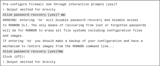
If you have forgotten the security appliance password and the password recovery process is disabled, the only way to recover out of this state is to erase all system files (including the software image and the configuration file). Make sure that the configuration and system image files are stored in an external server with IP connectivity to the security appliance. Use the following procedure to recover system passwords when password recovery is disabled:
Step 1. Establish a console connection.
This process requires you to have physical access to the security appliance, for security reasons. This is to ensure that remote or unauthorized users cannot reset passwords. Consequently, a console connection to the security appliance is required. Consult the “Establishing a Console Connection” section earlier in the chapter.
Step 2. Reload the security appliance.
You start the password recovery process by turning off the security appliance and then turning it back on.
Step 3. Break into ROMMON.
When the security appliance starts to reboot, the startup messages are displayed on the console. Press the Esc (Escape) key after Use BREAK or ESC to Interrupt Boot is shown. This displays a warning message saying that all files will be erased from flash if access to ROMMON is made. The following example illustrates this process:

Step 4. Erase system files from flash.
Before the security appliance allows a user to get access to ROMMON mode, it issues a prompt to erase all file systems. Press yes to start the process of erasing all system files. After all files have been erased, the security appliance enables the password recovery process and grants access to ROMMON mode.
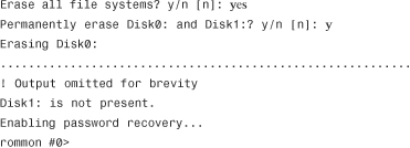
Step 5. Upload a system image.
When access to ROMMON mode is available, go through the image upgrade process discussed earlier in this chapter. The following example shows a system image, asa821-k8.bin, being uploaded from a TFTP server, 192.168.10.250:
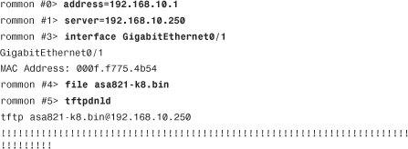
Note
The security appliance downloads the system image file in memory and boots up the device. However, the downloaded system image is not stored in flash.
Step 6. Upload a configuration file.
The security appliance loads a default configuration file without an interface configured. To upload a configuration file, the interface closest to the external file server must be set up to upload the saved file. In the following example, GigabitEthernet 0/1 is set up to upload a configuration file called Chicago.conf from a TFTP server located at 192.168.10.250 toward the inside interface:
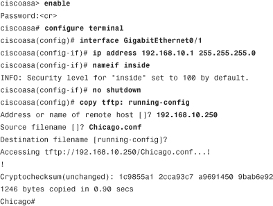
Step 7. Reset the passwords.
After uploading the saved configuration, change the login, enable, and user passwords. The login password is used to get user-mode access, and enable password is used to gain privileged mode access. In the following example, login and enable passwords are changed to C1$c0123:
![]()
If the security appliance is using local user authentication, the user passwords can also be changed, as follows:
Chicago# config terminal
Chicago(config)# username cisco password C1$c0123
Step 8. Save the current configuration into NVRAM.
Make sure that the newly specified passwords are stored in the saved NVRAM configuration. Do so by using the copy command to copy the running-config file in NVRAM as the startup-config:
Chicago(config)# copy running-config startup-config
Source filename [running-config]? <cr>
Load ASA image to Flash.
Finally, load the image from the TFTP server to the local flash. Follow the guidelines discussed under the “Image Upgrade via the Cisco ASA CLI” section earlier in this chapter.
System Monitoring
The security appliance generates system and debug messages when an event occurs. These messages can be logged to the local buffer or to an external server, depending on an organization’s security policies. This section discusses how to enable event logging and Simple Network Management Protocol (SNMP) polling, which can be used to check the security appliance’s status.
System Logging
System logging is a process by which the Cisco ASA generates an event for any significant occurrence that affects the system, such as network problems, error conditions, and threshold breaches. These messages can either be stored locally on the system buffer or be transferred to external servers. You can use these logs for event correlations to detect network anomalies or you can use them for monitoring and troubleshooting purposes.
The security appliance assigns a message ID to each event it generates. As of version 8.2, these message IDs range from 101001 to 741006 and contain a brief description of the event. The security appliance also associates each message ID to a severity level ranging from 0 to 7. The lower the severity level number is, the more critical the message is. Table 3-7 lists the severity levels, along with the associated keyword and a brief description.
Table 3-7 Severity Levels and Their Descriptions

Each severity level not only displays the events for that level but also shows the messages from the lower severity levels. For example, if logging is enabled for debugging (level 7), the security appliance also logs levels 0 through 6 events.
Note
For a complete list of all the severity messages, please consult the System Log Messages Guide located at www.cisco.com/go/asa under “Troubleshoot and Alerts.”
The next subsection discusses how to enable system logging (syslog) on the security appliance to log relevant events.
Enabling Logging
To enable logging of system events through ASDM, go to Configuration > Device Management > Logging > Logging Setup and select the Enable Logging option. This option enables the security appliance to send logs to all the terminals and devices set up to receive the syslog messages.
The security appliance does not send debug messages as logs, such as debug icmp trace, to a syslog server unless you explicitly turn it on using the Send debug messages as syslogs option. For UDP-based syslogs, the security appliance allows logging of messages in the Cisco EMBLEM format. Many Cisco devices, including the Cisco IOS routers and CiscoWorks management server, use this format for syslogging. Figure 3-21 illustrates that syslogging is globally enabled, with debugs being sent as syslogs to an external server in the EMBLEM format.
Figure 3-21 Enabling Syslog via ASDM
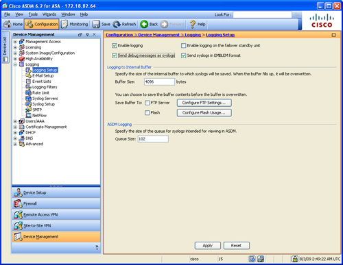
Example 3-43 shows the equivalent configuration in the CLI format.
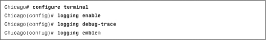
After the logging is enabled, ensure that the messages are timestamped before they are sent. This is extremely important because in case of a security incident, you want to use the logs generated by the security appliance to back trace. Navigate to Configuration > Device Management > Logging > Syslog Setup and select the Include timestamp in syslog option. If you prefer to use the CLI, use the logging timestamp command, as shown in Example 3-44.
Example 3-4 Enabling Syslog Timestamps
![]()
Defining Event List
The security appliance’s robust operating system enables you to define and choose the events and messages to be sent to specific different syslog stores. For example, you can choose to send all the VPN-related log messages to the local buffer, whereas all the other events can be sent to an external syslog server. You do so by defining a logging list under Configuration > Device Management > Logging > Event Lists > Add. ASDM prompts you to specify an “Event List” name, which can be used to specify the level of messages the security appliance should be logging. You can add events to this list based on either the Event Class or Message ID. In the Event Class option, you can classify messages using the predefined event classes to log specific processes and then assign appropriate severity to them. These classes include
• auth—Identifies user authentication messages
• bridge—Classifies transparent firewall events
• ca—Logs PKI certificate authority messages
• citrix—Classifies citrix client messages in sslvpn
• config—Logs the command interface–specific events
• csd—Classifies secure desktop messages
• dap—Logs dynamic access policies messages
• eap—Identifies EAP messages in NAC implementations
• eapoudp—Logs EAPoUDP messages in NAC implementations
• eigrp—Classifies EIGRP routing events
• email—Logs WebVPN email proxy messages
• ha—Logs failover events
• ids—Classifies the intrusion detection system events
• ip—Identifies IP stack messages
• ipaa—Identifies IP address assignment messages
• nac—Logs NAC messages in NAC implementations
• nacpolicy—Logs NAC policy messages in NAC
• nacsettings—Classifies NAC setting messages
• np—Logs network processor events
• ospf—Classifies OSPF routing events
• rip—Logs RIP routing messages
• rm—Identifies resource manager events
• session—Identifies user session–specific messages
• snmp—Classifies SNMP-specific events
• ssl—Logs SSL-specific events
• svc—Classifies AnyConnect client messages
• sys—Logs system-specific events
• vm—Classifies VLAN mapping messages
• vpdn—Classifies L2TP session messages
• vpn—Classifies the IKE- and IPSec-related messages
• vpnc—Identifies the VPN client–specific events
• vpnfo—Logs VPN failover messages
• vpnlb—Logs VPN load-balancing events
• webfo—Logs WebVPN failover messages
• webvpn—Logs WebVPN-related messages
Note
The default severity level for a logging list is 3 (errors).
In Figure 3-22, a logging list called IPSec_Critical is set up to group all the vpn (IKE and IPSec) messages. The selected severity level is critical, which also includes level 0 and level 1 events.
Figure 3-22 Defining Event Class for Logging via ASDM

Example 3-45 shows the equivalent configuration of Figure 3-22.
Example 3-45 Setting Up a Logging List
![]()
Logging Types
Cisco ASA supports the following types of logging capabilities:
• External syslog server logging
• External SNMP server logging
The followings sections describe each logging type in detail.
Console Logging
Console logging enables the security appliance to send syslog messages to the console serial port. This method is useful for viewing specific live events during troubleshooting.
Caution
Enable console logging with caution; the serial port is only 9600 bits per second, and the syslog messages can easily overwhelm the port.
If the port is already overwhelmed, access the security appliance from an alternate method, such as SSH or Telnet, and lower the console-logging severity.
Terminal Logging
Terminal logging sends syslog messages to a remote terminal monitor such as a Telnet or a SSH session. This method is also useful for viewing live events during troubleshooting. It is recommended that you define an event class for terminal logging so that your session does not get overwhelmed with the logs.
ASDM Logging
You can enable the security appliance to send logs to Cisco ASDM. This feature is extremely useful if you use ASDM as the configuration and monitoring platform. You can specify the number of messages that can exist in the ASDM buffer. By default, ASDM shows 100 messages in the ASDM logging window.
Email Logging
The security appliance supports sending log messages directly to individual email addresses. This feature is extremely useful when you are interested in getting immediate notification when the security appliance generates a specific log message. When an interesting event occurs, the security appliance contacts the specified email server and sends an email message to the e-mail recipient from a preconfigured e-mail account.
Syslog Server Logging
Cisco ASA supports sending the event logs to one or multiple external syslog servers. Messages can be stored for use in anomaly detection or event correlation. The security appliance allows the use of both TCP and UDP protocols to communicate with a syslog server. You must define an external server to send the logs to it, as discussed later in the “Defining a Syslog Server” section.
Cisco ASA also supports sending the event logs to one or multiple external SNMP servers. Messages are sent as SNMP traps for anomaly detection or event correlation. This is discussed in detail under the SNMP section.
Buffered Logging
The security appliance allocates 4096 bytes of memory to store log messages in its buffer. This is the preferred method to troubleshoot an issue because it does not overwhelm the console or the terminal ports. If you are troubleshooting an issue that needs to store more messages than it can store, increase the buffer size up to 16,384 bytes.
Note
The allocated memory is a circular buffer; consequently, the security appliance does not run out of memory as the older events get over-written by newer events.
In Figure 3-23, the logging level for the syslog server is set up for debugging. The figure also illustrates that the logging level for SNMP trap is an event list called FailoverCommunication, internal buffered logging is set to debug, email logging is set to the FailoverCommunication event list, Telnet and SSH sessions logging is set to the IPSec_Critical event list, syslogging is set to debug, and ASDM logging is set to the Informational level. The email and syslog server parameters are configured later in this chapter.
Figure 3-23 Forwarding Syslogs to Multiple Stores
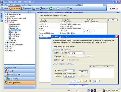
Example 3-46 shows the equivalent configuration of Figure 3-23.
Example 3-46 Setting Up a Logging List
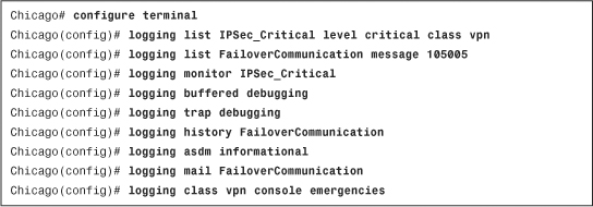
You can view the buffered logs by using the show logging command, as demonstrated in Example 3-47. This shows all different types of logging supported on the security appliance and indicates whether they are enabled or disabled. Additionally, it provides the number of messages logged on each of the configured logging types with the logging severity. Each syslog message starts with %ASA, to indicate that a Cisco security appliance generated the message, followed by the logging level, the unique message ID, and then a brief string to describe the log message.
Example 3-47 Output of show logging
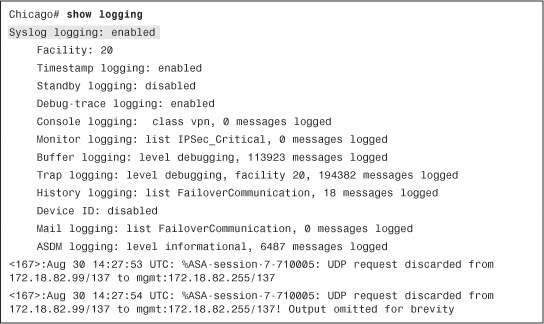
Defining a Syslog Server
You must define an external UDP- or TCP-based syslog server before the Cisco ASA can send logs to it. To define a syslog server, navigate to Configuration > Device Management > Logging > Syslog Servers > Add. ASDM prompts you to specify an interface where the syslog server resides, the IP address of the server, a selection of UDP or TCP port and the respective port numbers, and whether you want to send the log in the Cisco EMBLEM format to UDP-based syslog servers.
For TCP-based syslog servers, the security appliance
• Enables you to create a secure TLS connection so that the messages can be encrypted.
• Drops all new connections if the session to the syslog server cannot be established.
To enable secure communication between the security appliance and the TCP-based syslog server, select the Enable secure logging using SSL/TLS (TCP only) option. To allow new connections to be established if the TCP-based syslog server is down, enable the Allow user traffic to pass when TCP syslog server is down global option, which is configured in the “Syslog Servers” window.
In Figure 3-24, two syslog servers to which log messages are to be sent are defined. The first server collects the logs, using UDP and in the Cisco EMBLEM format, and the other server uses TCP port 1470 to accept the syslog messages. The security appliance sends all logging level 7 and below messages to these servers. The security appliance is configured to establish secure connection with the TCP-based syslog server. If the syslog server is not enabled, the security appliance continues to establish new connections.
Figure 3-24 Defining Syslog Servers
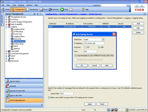
Example 3-48 shows the equivalent configuration of Figure 3-24.
Example 3-48 Setting Up Syslog Servers
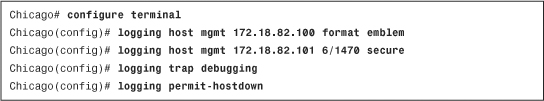
Defining an Email Server
The security appliance enables you to send sensitive log messages via an email. This is extremely useful if you are monitoring a specific event or a group of events and want to get alerted right away when it occurs. To define a new SMTP server, navigate to Configuration > Device Management > Logging > SMTP and specify the IP address of the primary and optionally the secondary SMTP server. Additionally, you must specify the source and destination email addresses. You can define them by choosing Configuration > Device Management > Logging > E-Mail Setup. The source address is used to generate the log messages, whereas the destination email address is where the messages are sent.
In Example 3-49, a logging list called FO_Cable is set up with a message ID of 101002 to classify the failover cable issues. This logging list is linked to send email messages from [email protected] to [email protected], using 192.168.10.50 as the primary email server and 192.168.10.51 as the secondary email server.
Example 3-49 Configuration of Email Logging
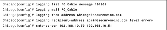
Storing Logs Internally and Externally
The ASA enables you to save the buffered log messages as files to the local flash or to an FTP server for future analysis. The security appliance supports two methods to save buffered logs:
Flash Logging
Using the flash logging method, you can save the log messages located in the buffer space to the local flash (disk0: or disk1:). The security appliance creates a file in the /syslog directory of flash, using the default name of LOG-YYYY-MM-DD-HHMMSS.TXT, where YYYY stands for year, the first MM for month, DD for days, HH for hours, the second MM for minutes, and SS for seconds. Navigate to Configuration > Device Management > Logging > Logging Setup and enable the Save Buffer to Flash check box. If you click the Configure Flash Usage, you can specify the following options:
• Maximum Flash to Be Used by Logging—The maximum space the security appliance can use to store the buffered logs in flash.
• Minimum Free Space to Be Preserved—The minimum space in kilobytes that the security appliance should maintain to ensure that there is room left in flash for other administrative tasks.
Note
The Cisco ASA uses the local clock settings to add the timestamp. Consult the “Setting Up the System Clock” section earlier in this chapter.
Example 3-50 shows that the security appliance is allocating 2 MB of space to save logs in flash and the minimum free space in flash should be 4 MB.
Example 3-50 Automatic Saving of Logs in Flash
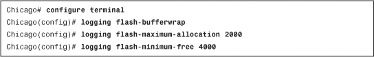
Tip
The Cisco ASA also enables you to manually save the buffered logs to the local flash if you issue the logging savelog command. You can check the flash directory by using the dir /recursive command. The /recursive option shows the complete file structure of the Flash by displaying all files even if they are located in sub-directories.
FTP Logging
The security appliance can transfer the buffer logs to an FTP server to conserve disk space. You enable this by navigating to Configuration > Device Management > Logging > Logging Setup and enabling the Save Buffer to FTP Server check box. You must click Configure FTP Settings, then the Enable FTP Client check box and specify the IP address, username, and password.
In Example 3-51, an appliance is set up to send log files to an FTP server, located at 192.168.10.150. The username to log in to the FTP server is cisco with a password of C1$c0123. The logs will be stored in the root directory (.) of the FTP server for that user.
Example 3-51 Automatic Saving of Logs in the FTP Server

Syslog Message ID Tuning
The security appliance sends all log messages to the logging devices, internal and external. However, if you are not interested in logging a particular message, you can suppress it by navigating to Configuration > Device Management > Logging > Syslog Setup, selecting the message ID, clicking Edit and selecting the Disable Messages check box. You can also achieve the same result with the CLI by issuing the no logging message command followed by the message ID number, as shown in Example 3-52, where message ID 101001 is disabled.
Example 3-52 Disabling a Message ID
![]()
Even though the debug-level syslogs provide extensive information about the traffic and device health, many enterprises do not want to enable syslogs at that level. They choose to enable logging at information or notification level and then move the appropriate debug-level message to a lower level. You can change a message’s logging level by navigating to Configuration > Device Management > Logging > Syslog Setup, selecting the message ID, clicking Edit, and selecting the appropriate level under Logging Level.
NetFlow Secure Event Logging (NSEL)
Cisco security appliance supports using the NetFlow architecture to send syslogs, if you are using version 8.2(1) or higher. If you are using ASA 5580s, you can also enable this feature in the 8.1(1) version of the software. Sending logs via syslog is considered inefficient because
• Syslog sends logs in the ASCII text format, which produces logs that are verbose and lengthy.
• Syslog generates a single UDP packet for each log messages, which results in a large number of small packets.
• Generating lots of text-based syslogs adds considerable load on the security appliance.
Using NetFlow as a means to send syslogs can greatly enhance performance. The security appliance generates log information in binary, which can be parsed easily and sends multiple records in a single flow packet.
Note
You must have a NetFlow collector in your network that can parse the flow of information the security appliance sends. CS-MARS running version 6.0 can read and parse NetFlow v 9 information. To learn more about NetFlow version 9, consult RFC 3954.
Cisco ASA uses NetFlow version 9, which leverages the template-based approach as a flow export mechanism. The NetFlow template defines the structure of the NetFlow record being exported. The NetFlow implementation exports records when a significant event in the life of a flow, such as creation and teardown, occurs. The security appliance also exports information about flows that are allowed or denied by access control lists (ACLs). ACLs are discussed in Chapter 4.
You cannot display the NetFlow packets on a terminal session, unlike what you can do with a Cisco IOS router, where you can view the NetFlow data via a terminal session. Additionally, the security appliance exports the flow information periodically to a collector. This is also different from the typical NetFlow version 9, such as on a Cisco IOS router, where the flows are exported in a single packet when a number of flows are collected.
When you are exporting logs via NetFlow, you do not want to send the same logs via syslog to avoid duplication of packets. The security appliance allows you to disable all syslogs messages that generate the same information as NetFlow. This way, you do not have to manually disable individual syslogs in the ASA configuration. The security appliance disables 106015, 106023, 106100, 302013, 302014, 302015, 302016, 302017, 302018, 302020, 302021, 313001, 313008, and 710003 syslog messages.
The configuration of NSEL can be broken into two steps:
Step 1: Defining a NetFlow Collector
Using ASDM, you can define a NetFlow collector by navigating to Configuration > Device Management > Logging > NetFlow > Add under “Collectors”. You can specify the IP address, the UDP port that your collector uses for NetFlow packets, and the interface where the collector resides.
You can optionally configure a delay in sending the flow creation event. This option is useful if you have a large number of created connections so that the appliance can package them up into fewer export packets. If the flow is torn down before the configured delay, only the flow teardown event is dispatched and the flow creation event is not sent. You configure this by selecting the Delay transmission of flow creation events for short-lived flows check box.
The security appliance sends the template record to your NetFlow collector, by default, every 30 minutes. You can change the frequency when the template record is sent, in minutes, under the Template Timeout Rate option box. The default timeout value of 30 minutes works in most cases.
Figure 3-25 illustrates that a new NetFlow collector is being added. It is located toward the mgmt interface at 172.18.82.81 and listens on UDP port 2055. The Disable redundant syslog messages check box is also enabled to avoid duplication of syslog messages.
Figure 3-25 Defining NetFlow Collector

Example 3-53 shows the equivalent configuration of Figure 3-25.
Example 3-53 Configuring NetFlow via CLI
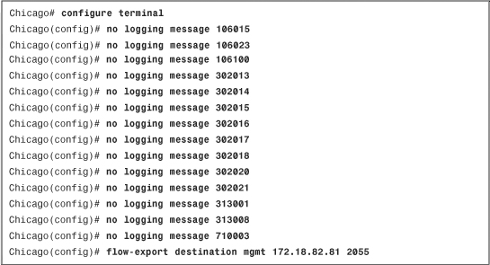
Step 2: Defining a NetFlow Export Policy
The security appliance does not send NetFlow to an external collector until you classify the traffic type it should be monitoring to generate the NetFlow events. For example, if you want it to monitor all traffic for NetFlow exports, specify a global policy that analyzes all traffic. NetFlow export policy is constructed via the modular policy framework (MPF), discussed in Chapter 7 and 11. Follow these steps to successfully configure an export policy:
Step 1. Navigate to Configuration > Firewall > Service Policy Rules, select inspection_default policy, and then click Add > Insert After. ASDM launches a Service Policy Rule Wizard where you can select Global—applies to all interfaces. Click Next.
Step 2. Under Traffic Match Criteria, specify a traffic class name of NetFlow. Select Any Traffic as the Traffic Match Criteria and click Next.
Step 3. Under Rule Action, click the NetFlow tab and click Add. A new window opens where you can specify Flow Event Type. Select All and enable the Send check box next to the collector’s IP address. This collector was defined under the preceding “Defining a NetFlow Collector” section. Click OK and then Finish to complete defining a NetFlow export policy.
If you prefer to use the CLI, you can define an identical policy as shown in Example 3-54.
Example 3-54 Defining an NetFlow Export Policy
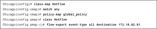
Cisco ASA also enables you to monitor the status of the NetFlow exports if you use the show flow-export counters command as shown in Example 3-55. It shows you the number of export packets sent and statistics about any potential export issues.
Example 3-55 Monitoring NetFlow Exports

Simple Network Management Protocol (SNMP)
SNMP is an application layer protocol that was developed to monitor the health of network devices. It has become a de facto standard because of its simple protocol design. A successful SNMP implementation requires a management station, also known as the manager, and at least one agent, such as the Cisco ASA. The network management station, such as CiscoWorks, monitors the agents by collecting the device and network information and presenting it in a GUI. The agents, on the other hand, respond to the manager’s request for information. If an important event occurs, the agents can also initiate a connection to the manager to send the message.
The SNMP implementation uses the following five message types, known as protocol data units (PDUs), for the communication between the management station and the agent:
• GET
• GET-NEXT
• GET-RESPONSE
• SET
• TRAP
The network manager uses the Management Information Base (MIB) to initiate the GET and GET-NEXT messages and request specific information. The agent replies with a GET-RESPONSE, which provides the requested information, if available. In a case where the requested information is not available, the agent sends an error detailing why the request cannot be processed.
The network manager uses the SET message type to change or add values in the configuration rather than retrieve the information. The agent replies with a GET-RESPONSE message to indicate whether the change was successful. The TRAP messages are agent-initiated to inform the network manager about an event, such as a link failure, so that an immediate action can be taken. Figure 3-26 illustrates the PDU communication between a security appliance, as an agent, and a CiscoWorks server, as a management server.
Figure 3-26 SNMP Communication Between the Cisco ASA and CiscoWorks

Note
The security appliance does not allow SET PDUs, for device-security reasons. Consequently, you cannot use SNMP to modify the configuration of the security appliance.
Configuring SNMP
The security appliance must be configured before a network management server can initiate a connection. Configure SNMP on a security appliance through ASDM by navigating to Configuration > Device Management > Management Access > SNMP and following these steps:
Step 1. Configure a global community string.
A community string acts as a password when the management server tries to connect to the security appliance to get information. It is used to validate the communication messages between the devices. In ASDM, specify a global community string under “Community String (Default)”. If you prefer to use the CLI, set a global community string by using the snmp-server community command.
Step 2. Set device information.
Specify the location of the security appliance so that the SNMP server knows where the device is physically located. The security appliance enables you to set up contact information for an individual who is responsible for it. In ASDM, specify the device information, such as the Contact and ASA Locations options. If you prefer to use the CLI, use the snmp-server location and snmp-server contact commands.
Step 3. Modify SNMP Polling ports.
The Cisco ASA can be configured to listen on a nondefault port for SNMP polls. To use a port other than UDP 161, specify it under the “Listening Port” option. If using the CLI, use the snmp-server listen-port command, followed by a port number.
Step 4. Define an SNMP server.
You must specify an SNMP management server before the ASA can listen for polls or send SNMP traps. To define a new SNMP server, click Add under SNMP Management Stations and specify the following information:
• Interface Name—The name of the interface where the SNMP server resides. In most cases, it is the inside or the management interface. If you select an interface other than the inside interface, ASDM generates a warning that you should consider about using an inside interface for security reasons. However, using a management interface is as secure if you have a dedicated management network.
• IP address—The actual IP address of the SNMP server. The IP address must reside toward the interface selected
• UDP Port—The security appliance uses UDP port 162 when it needs to send SNMP traps to the management server. If the SNMP server listens on a different port, you can change the UDP port on the security appliance by specifying a port under the “UDP Port” option.
• SNMP Version—The security appliance supports SNMP versions 1, 2c, and 3. Version 2c overcomes the deficiencies and problems associated with version 1. It uses the administrative framework of version 1 but enhances protocol operations by increasing security capabilities. SNMPv3 adds many security and remote configuration enhancements such as message integrity (to ensure that a packet has not been tampered with in transit), authentication (to verify that the message is from a valid source), and encryption (to prevent snooping by an unauthorized source). If you select SNMP version 3, you must define a username. If you select SNMP version 1 or 2c, ASA enables you to specify a host-specific SNMP community string.
• Server Poll/Trap Specification—The security appliance allows an SNMP server to poll information from the security appliance. It also sends event traps when unusual incidents occur. You can optionally restrict the security appliance to allow either SNMP polls only or traps only. In most implementations, an SNMP server is designed to poll as well as receive traps from the network devices.
Step 5. Configure SNMP traps.
The security appliance sends limited SNMP traps by default; however, you can configure it to send all supported traps or a superset of all traps. Do so by clicking the Configure Traps icon and selecting the following trap types:
• Standard event traps—These traps include interface link up/link down, authentication, and device cold start.
• IPSec event traps—These include IPSec tunnel start and stop traps.
• Remote-access traps—The security appliance generates a trap when remote-access sessions reach the session threshold limit.
• Entity traps—These traps are sent when changes are made to the device, such as configuration modification or insertion/removal of hardware modules into or from the chassis.
• Syslog traps—The security appliance sends syslog messages as SNMP traps to the management station.
Note
To set up traps for syslog messages, you must determine what severity of syslog messages need to be forwarded to the management server. This was discussed earlier in the “Logging Types” section.
In Figure 3-27 a new SNMP server is being added. The IP address of the server is 172.18.82.90 and it is located toward the mgmt interface. The server is configured to use SNMP version 3, which requires you to configure a username. The configured user name is cisco.
Figure 3-27 SNMP Server Definition
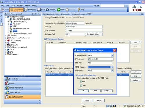
Example 3-56 shows equivalent configuration of Figure 3-27.
Example 3-56 Automatic Saving of Logs in the FTP Server

SNMP Monitoring
The show snmp-server statistics command is useful for checking the statistics of the SNMP engine. It displays not only the total SNMP packets received and transmitted but also any bad or illegal packets handled by the security appliance. Example 3-57 displays the output of this command, where the security appliance received 12 GET requests and replied to all of them as GET-RESPONSE.
Example 3-57 Output of show snmp-server statistics
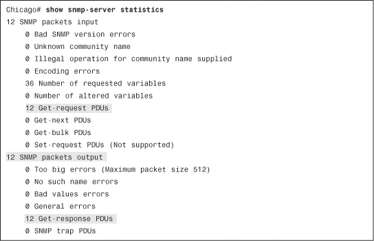
Device Monitoring and Troubleshooting
Cisco ASA is loaded with a number of show and debug commands to monitor the health of the device and troubleshoot any network- or device-level issues.
CPU and Memory Monitoring
The show cpu usage command indicates current CPU utilization. It displays an approximation of load over 5, 60, and 300 seconds. Example 3-58 shows that the 5-second utilization is 2 percent, whereas the 1-minute and 5-minute utilizations are 1 percent.
Example 3-58 Output of show cpu usage
![]()
The security appliance can display memory usage through the show memory command. It shows a summary of the available and allocated memory in bytes and as a percentage. In Example 3-59, the free memory on the security appliance is 849,120,760 bytes (~810 MB), and the allocated or used memory is 224,621,064 bytes (~214 MB). The total memory on the security appliance is 1024 MB.
Example 3-59 Output of show memory
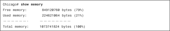
Note
Using the show memory detail command output with show memory binsize enables you to check the number of bytes allocated to a given size memory chunk. These commands should be used under a TAC engineer’s supervision if advanced memory troubleshooting needs to be done.
The security appliance can display the system buffer utilization if the show block command is executed. When the security appliance boots up, the operating system carves out memory to create the maximum number of blocks for different block sizes. The maximum number of blocks does not change, except for the 256- and 1550-size blocks. For these blocks, the security appliance can dynamically create more blocks if necessary. The security appliance allocates a block from the pool when it needs to use it, and returns it when it is done using it.
There are eleven different sizes of buffer blocks, and each buffer type is responsible for handling specific packets. Table 3-8 shows the buffer block sizes and provides a brief description on where they are used.
When you run the show block command, the security appliance displays the following counters:
• MAX—Indicates the maximum number of blocks available for a specific block size.
• LOW—Indicates the lowest numbers of blocks available at one point since the last reboot or the last time the counters were cleared by the clear block command. A low count of 0 indicates that the security appliance had run out of buffer space for a particular block at some point since the last reboot or the last time the counters were cleared.
• CNT—Displays the currently available blocks for each block size
In Example 3-60, the security appliance has allocated 300 blocks for the 4-byte block size, and it is currently using one block. The LOW counter is set to 299 because the security appliance had allocated only one block of it since the last reboot.
Example 3-60 Output of show block
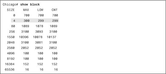
Using ASDM, you can monitor the health of a security appliance by navigating to Monitoring > Properties > System Resources Graphs and selecting a graph for Block use, CPU utilization and memory use and availability.
Troubleshooting Device Issues
Cisco ASA provides a number of troubleshooting and diagnostic commands for troubleshooting traffic as well as device-related issues.
Troubleshooting Packet Issues
In any firewall deployment, administrators spend most of their time defining new policies and troubleshooting packet flow issues. The following sections discuss three scenarios to show how the security appliance assists in troubleshooting those issues.
Tracing Packet Flow
To learn which processes are being applied to a packet flow, use the packet tracer feature. Using this feature, describe how a packet should be structured based on the IP protocol, source and destination IP addresses, and source and destination ports. The security appliance provides information when that packet goes through different processes such as the access-control lists (ACLs), routing, and address translation (NAT). Each process inspects the packet individually and decides whether it needs to allow or deny that packet.
Use this feature by choosing Tools > Packet Tracer and specifying the interface from which the packet should be coming, the IP protocol, and the source and destination IP addresses and ports. As illustrated in Figure 3-28, the administrator is tracing a TCP packet sourced toward the inside interface from 192.168.10.50 and destined to 209.165.200.229 on source port 1024 and destination port 80. Each process checks the packet and allows it, the end result is successful, and that packet is allowed to pass through the security appliance.
Figure 3-28 Tracing Packets Through the Security Appliance

Example 3-61 shows the CLI equivalent of Figure 3-28.
Example 3-61 Tracing Packet Through the CLI
![]()
Capturing Packets
One of the most robust features in the security appliance for troubleshooting traffic-related problems is the packet capture feature. When packet capture is turned on, the security appliance sniffs interesting traffic and stores it in the buffer. This is important if you want to confirm that traffic from a particular host or network is reaching the interfaces. You can use an ACL to identify the type of traffic and bind it to an interface by using the capture command. The captured packets can be viewed either locally on the security appliance or on an external device such as Wireshark if you export the information in the pcap format.
In Example 3-61, an ACL, called inside-capture, is set up to identify packets sourced from 209.165.202.130 and destined for 209.165.200.230. The security appliance is using this ACL to capture the identified traffic on the inside interface, using a capture list named cap-inside.
To view the captured packets, use the show capture command, followed by the name of the capture list. In Example 3-62, the security appliance captured 15 packets that matched the ACL on the inside interface. The highlighted entry shows that it is a TCP SYN (shown as “S” after the destination port) packet sourced from 209.165.202.130 with a source port of 11084 and it is destined for 209.165.200.230 on destination port 23. The TCP window size is 4128, and the Maximum Segment Size (MSS) is set to 536 bytes.
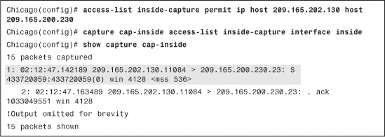
Note
When the capture command is enabled, the security appliance allocates memory right away. The default memory allocation is 512 KB. The security appliance can overwrite content when the allocated memory is full by removing the oldest entry first. The capture command has minimal CPU impact and therefore it is one of the most important troubleshooting tools available in Cisco ASA.
The output of the capture command can be exported into pcap format, which can be imported into a sniffing tool such as Wireshark or TCPDUMP for further analysis. To download the file in pcap format, use https://<IPAddressOfASA>/capture/<CaptureName>/pcap in a browser. For example, to download the pcap file for the capture defined in Example 3-62, use https://172.18.82.64/capture/cap-inside/pcap.
Tip
To see traffic in real time, use the real-time keyword in the capture. For example, the capture command in Example 3-61 can be defined for real-time traffic analysis as capture out-inside access-list inside-capture interface inside real-time. Even though real-time capturing is extremely useful in troubleshooting traffic-related issues, the security appliance displays up to only 1000 packets in case of excessive traffic load.
Monitoring Dropped Packets
The security appliance, being a firewall, drops packets if they do not adhere to an enterprise’s security policy. These drops could be related to the deny statements in the ACLs, illegitimate VPN packets, a malformed TCP segment, or a packet with invalid header information. In some cases, you will want to get the statistical information about the packets or connections dropped by the security appliance within its accelerated security path (ASP). Use the show asp drop command as shown in Example 3-63, which shows that over 57,000 packets were dropped because of the deny statement in the ACLs.
Example 3-63 Output of show asp drop
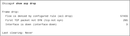
Note
For a complete list of asp drop reasons, refer to the command reference guide for the security appliance.
You can see that the security appliance has dropped over 57,000 packets because they were denied by the ACLs. About 300 packets were dropped because the adaptive security appliance received a non-SYN packet as the first packet of a connection. This usually occurs when the client and server believe that a connection was opened but the firewall has already closed that session. Finally, the security appliance dropped three packets when the interface was shut down.
Note
The security appliance enables you to capture on a specific drop type or all asp drop types through the capture command, as follows:
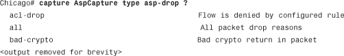
Troubleshooting CPU Issues
If you are monitoring your CPU utilization and it is constantly running high, you can activate the CPU profiling feature on the security appliance by using the cpu profile activate command. You can also allocate memory for storing a specific number of samples, which can vary from 1 to 100,000, with the default being 1000. The more memory you allocate to this process, the better the accuracy for CPU profiling. After CPU profiling is activated, use the show cpu profile output to view the output. Unfortunately, you have to send the output of this show command to a TAC engineer for analysis.
Summary
This chapter introduced the different CLI modes and discussed the initial configuration of the Cisco ASA. It presented a brief overview of the networking technologies, such as IPv6, DHCP, NTP, and SNMP, and provided examples of how to set them up. Telnet and SSH were discussed as the remote-management protocols. This chapter also assisted in system maintenance features such as image upgrade and password recovery methods. The last section discussed the security appliance monitoring capabilities, such as system logging, SNMP, and a set of show commands to check the device’s status and health.