
Chapter 10. Failover and Redundancy
With more organizations moving toward e-commerce, dependence on both LANs and WANs has increased drastically. They cannot afford to lose connectivity with their core servers in the network infrastructure. This connectivity loss could cause multimillion-dollar revenue losses per minute. Consequently, organizations want to deploy and maintain reliable network devices to ensure nonstop availability and nearly 100 percent uptime. They do so by implementing layers of redundant devices to prevent interruption should any network component fail.
Because Cisco is fully committed to provide a resilient infrastructure to its customer base, Cisco ASA provides many valuable failover features to suit your environment. For failover to work, you must have two Cisco ASA devices connected to each other, using a dedicated network connection. The appliances have to be identical in terms of hardware model, number of interfaces, and the software license. Thus, if one of the appliances fails to perform its duties, the other appliance takes over and seamlessly starts passing traffic.
Architectural Overview
When two identical Cisco ASAs are set up in failover, one of the appliances, the active appliance, is responsible for creating the state and translation tables, transferring the data packets, and monitoring the other unit. The other security appliance, the standby appliance, is responsible for monitoring the status of the active unit. The active and standby appliances are connected through a dedicated network link to send failover-related messages to each other. This connection, known as a failover control link, is established over a dedicated failover LAN interface. When a failure occurs on the active appliance, the standby takes over the active role and starts forwarding traffic. This newly active appliance also takes over the IP and MAC addresses that were used by the previous appliance. After the failed unit recovers, it assumes the standby role.
The failover control link provides a medium over which the two security appliances can communicate and update one another about:
• The unit state (whether active or standby)
• Network link status
• Hello or keepalive messages (which are sent on all interfaces)
• MAC address exchange
• Configuration replication from active to standby
Figure 10-1 shows two Cisco ASA devices connected to each other through the GigabitEthernet interfaces. The GigabitEthernet0/2 interface is used as the failover link, shown as the dotted line.
Figure 10-1 Failover Setup Between Two ASAs

Conditions that Trigger Failover
For failover to occur, any one of the following conditions has to be met:
• An administrator manually has switched over from active to standby—This happens when either no failover active is issued on the active unit or failover active is issued on the standby unit.
• The active appliance has lost power or crashed due to hardware/software defects.
• A standby appliance has stopped receiving hello (or keepalive) packets on the failover control interface—In this condition, if the standby unit does not receive three consecutive hello packets, it sends additional testing packets to the remaining data-passing interfaces. If it still does not receive a response from the active unit, it assumes that a failure has occurred and takes over the role of the active appliance.
• The failover control interface link is down—In this scenario, the security appliance sends additional testing packets to the remaining interfaces to determine whether the peer’s control interface is also down. If the peer’s control interface is also down then failover does not occur and the failed interface is marked as “Failed.” However, if the peer’s control interface is not down, then failover occurs because the standby is deemed healthier then the current active appliance.
• The link state of a data-passing interface is down—In this condition, the appliance marks the interface as failed and initiates the failover process. Additionally, if the standby appliance does not receive the hello packets for two consecutive polling periods on an interface, the appliance goes through a series of additional tests on the interface to determine the root cause of the problem. These tests are discussed in detail in the following section.
Note
When using the Active/Active failover and the preempt command, discussed later in the “Active/Active Failover” section, the failover group might change which firewall is active for a context based upon whether the preferred physical unit is online and healthy.
Failover Interface Tests
To ensure that a failure is properly detected on monitored interfaces before initiating a failover, the security appliance goes through four different interface tests. These tests are discussed in the order in which they are checked:
• Link up/down test—The security appliance determines the status of its network interface card (NIC) by doing the link up/down test, which finds out whether one of the ports on the security appliance is not plugged into an operational network. In this case, the security appliance marks the interface as failed and initiates the failover process. Some examples of this failover include hardware port failure, unplugged cable of an interface, and a failure on the hub or switch to which the interfaces are connected. If the interface passes the link up/down test, the security appliance moves to the network activity test.
• Network activity test—In this test, the security appliance counts all received packets for up to 5 seconds. If the security appliance receives any packet during this time interval, it stops this test and marks the interface operational. If no traffic is received, the test is inconclusive, so the security appliance proceeds to the next test.
• ARP test—In the ARP test, the security appliance reads its ARP table for the last ten acquired entries. It sends an ARP request to those machines one at a time, and then counts packets for up to 5 seconds. If it receives traffic during this time window, it marks the interface as operational. If it does not receive a response from the host, it moves to the next host and sends an ARP request, and so on. At the end of the list, if the security appliance does not receive any traffic, it moves on to the ping test.
• Broadcast ping test—In this test, the security appliance sends out a broadcast ping request and then counts all received packets for up to 5 seconds. If it receives any packets during this time window, the security appliance declares this interface operational and stops the test. If the appliance does not receive any traffic, it marks the interface as failed and initiates failover.
Note
Although the network activity, ARP, and broadcast ping tests are time consuming, they do help avoid unnecessary failover on the security appliance. Even when an interface is going through these tests, the security appliance forwards traffic on the remaining interfaces.
If both active and standby interfaces fail all tests, then both interfaces go into the “unknown state.” The interfaces with the unknown state do not count toward the monitored interface failover limit. Interface monitoring is discussed in the “Monitoring Failover Interfaces” section.
Stateful Failover
When a connection is established through the active appliance, Cisco ASA updates its connection table. A connection entry includes the source and destination IP addresses, protocol used, current state of the connection, the interface to which it is tied, and the number of bytes transferred. Depending on the failover configuration, the security appliance takes one of the following actions:
• Stateless failover—The security appliance maintains the connection table but does not replicate entries to the standby appliance.
• Stateful failover—The security appliance maintains the connection table and replicates it to the standby appliance.
In a stateless failover, the active appliance is not responsible for sending the state table updates to the standby appliance. When the standby unit becomes active (whether by detecting a failure or by manually switching over), it has to build all the connection entries from scratch. This causes all the stateful traffic, such as TCP, to get disrupted.
In a stateful failover, the active appliance sends an update to the standby unit whenever there is a change in the state table. In this mode, the active appliance sends stateful updates over a dedicated link to the standby unit. When the standby unit becomes active, it does not need to build any connection entries because all the entries already exist in its database. This dedicated connection is known as the stateful link.
Note
You can use the same physical interface for both failover control and stateful link updates. However, it is not recommended if your appliances generate a lot of state updates. Additionally, it is recommended that you use the fastest interface as the stateful link and that the latency for the link should be less than 10 milliseconds to avoid performance degradation.
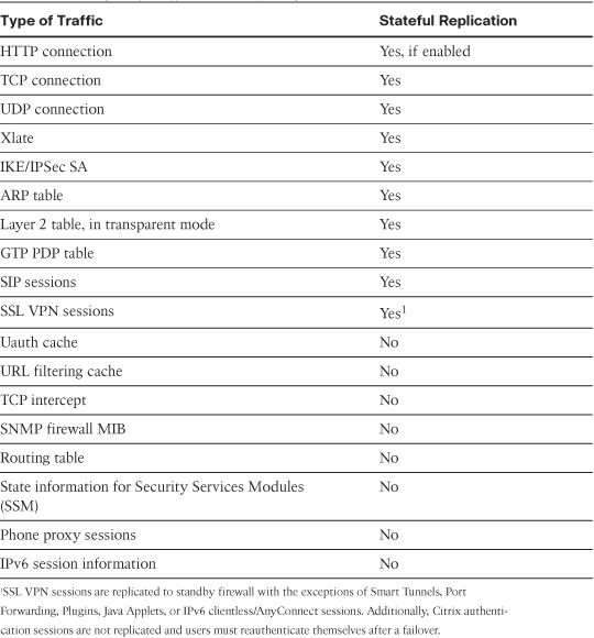
Table 10-1 lists the entries and the types of traffic that are replicated to the standby appliance in the stateful failover.
Table 10-1 Types of Traffic and Stateful Replication
Note
The security appliances replicate IPSec states only if stateful failover is used in Active/Standby. Any form of VPN is not supported in multimode firewall, and Active/Active failover works only in multimode.
Hardware and Software Requirements
For failover to work properly, the following specifications must be identical:
• Product or model number of the appliance—For example, both appliances must be Cisco ASA 5520. You cannot use an ASA 5520 and an ASA 5540 in failover.
• Amount of RAM—You cannot use 512 MB of RAM in one appliance and 1024 MB in the other one.
• Number of interfaces—Both appliances must have the same number of physical interfaces. For example, if you plan to deploy ASA5580s in your network in failover, then you cannot have mismatched interfaces on the two security appliances. Additionally, interfaces must be of the same type. You cannot use copper-based interfaces on one of them and fiber-based interfaces on the other.
• External Module—If you have a security module such as SSM-IPS, then both appliances must have it.
• Activation key with the same features—The activation key must have the same features, such as the failover mode, encryption level, and number of VPN peers.
Note
The software version does not have to be the same on the security appliances when failover is configured. This is called zero-downtime software upgrade, covered later in this chapter.
Before setting up security appliances for failover, verify that they have a valid license to run failover. After you verify the activation key, you can proceed with failover configuration.
Additionally, it is recommended that you use the same size of Flash memory on both appliances.
Types of Failover
Cisco ASA supports two different types of failover: device-level failover and interface-level failover.
Device-Level Failover
In device-level failover, if the active appliance starts experiencing issues such as hardware failure, the standby device can change its role and become the active device in the network. In the initial device-level failover configuration, you designate one device as primary and the other one as secondary. If both devices are powered on at the same time, then the primary appliance becomes active while the secondary appliance assumes the standby role. If the primary/active device experiences issues and a failover occurs, then the secondary appliance becomes active. When the primary appliance recovers, it keeps itself in the standby role until a failover occurs on the secondary/active appliance.
Cisco ASA supports two different types of device-level failover:
Note
Device-level failover supports up to two physical security appliances.
Active/Standby Failover
Active/Standby failover is identical to the failover scenario described earlier in the chapter where the active unit is responsible for passing the traffic and the standby appliance monitors the status of the active appliance. Both appliances send hello messages to monitor the status of one another.
Note
Cisco 5505 security appliances support Active/Standby stateless failover only if a Security Plus license is purchased. You cannot use failover on an ASA 5505 if it is used as an EasyVPN client. EasyVPN client functionality is discussed in Chapter 17, “IPSec Remote-Access VPNs.”
In Active/Standby failover, the Cisco ASAs go through the following election process. They assume roles based on their designated status, whether primary or secondary.
Step 1. When both appliances are up and running, one of them assumes the active role while the other appliance assumes the standby role.
Step 2. If both devices boot up simultaneously, the primary appliance takes over the active appliance role, and the secondary appliances goes into the standby state. The primary uses the active IP address and its MAC-address as the Layer 3 and Layer 2 addresses respectively. If failover occurs, the secondary firewall keeps using the IP address and primary’s MAC address as the active addresses.
Step 3. If one of the security appliances boots up and detects an active failover unit, it goes into the standby state regardless of its primary or secondary designation.
Step 4. If one of the security appliances boots up and does not detect an active failover unit, it goes in the active state regardless of its primary or secondary designation.
Step 5. In case both appliances become active, the secondary changes its state to standby as soon as it discovers another active primary firewall, while the primary remains active.
Step 6. In case both appliances become standby, the primary changes its state to active, while the secondary remains standby after they detect each other’s state.
Active/Active Failover
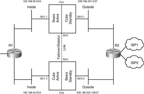
Active/Active failover is a feature in which both appliances, while monitoring the status of their peers, actively pass traffic. The appliances in Active/Active failover mode can be deployed only in multimode, discussed in Chapter 8, “Virtualization.” Figure 10-2 shows a network topology where two appliances are set up in stateful multimode Active/Active failover. The primary appliance is named FO1 and the secondary appliance is named FO2. The appliances are set up for two customer contexts: Cubs and Bears. In this deployment, the Cubs security context is active on FO1 and standby on FO2. However, the Bears security context is active on FO2 and standby on FO1. If FO1 fails, the standby security context on FO2 for Cubs becomes active and takes over the IP and MAC addresses of FO1. As a result, both security contexts will be active on FO2.
Figure 10-2 Appliances in Active/Active Multiple Mode

If stateful failover is turned on, the device failover is completely transparent to the end hosts because the firewalls replicate state and connection tables. When the security appliances are deployed in Active/Active mode, both the Primary and Secondary firewalls pass traffic and thus the firewall resources are efficiently utilized. If one of the appliances fails, the active firewall passes all traffic; it is therefore recommended that you do not oversubscribe the failover pair.
A key point to remember is that the failover in the Cisco ASA is per failover redundancy group (discussed in the section, “Failover Configuration”) as opposed to per-context failover. The Cisco ASA’s failover is currently limited to only two failover redundancy groups.
Note
If you are sharing an interface between multiple contexts, all those contexts need to be in the same failover redundancy group.
In Active/Active failover, it is possible that packets can leave from one active unit and can return to the other active unit. Cisco ASA implements a feature known as asymmetric routing to guide packets back to the context from which they originated. This feature is discussed in the following section.
Active/Active Failover and Asymmetric Routing
Many enterprise customers use multiple ISPs to get connectivity to the Internet or to their remote locations. Depending on their implementation, these enterprises can use these ISPs to either load-balance traffic or back each other up in the event of a failure.
Figure 10-3 depicts two appliances connected to two different ISPs and running in Active/Active failover with multiple contexts. Context Cubs is active on FO1, whereas context Bears is active on FO2. The problem arises when both ISPs are load-balancing the traffic out to the cloud and both appliances are in Active/Active mode. If Host A, sitting behind context Cubs, sends out a TCP SYN packet to Host B, the packet can leave the active appliance (FO1). However, there is no guarantee that the SYN-ACK, the reply from the server, will be routed back through the same unit. If the SYN-ACK packet lands on the other active appliance (FO2), FO2 drops the packet because it does not have the connection table entry for the original SYN packet.
Figure 10-3 Asymmetric Routing

Note
The asymmetric routing feature is supported only in multimode. Asymmetric routing is not supported if the appliances use shared interfaces.
If the asymmetric routing functionality is enabled, the appliances restore asymmetric routed packets to the correct interface. FO1 will replicate the connection table entry for the SYN packet to FO2 over the stateful failover link. Thus, when the active context on FO2 (Bears) receives the SYN-ACK packet, it will forward the packet to FO1 because it belongs to context Cubs, which is active on FO1. Figure 10-4 depicts all the steps when Host A communicates with Host B.
Step 1. Host A sends the SYN packet to its gateway router.
Step 2. The gateway router consults its routing table and forwards the SYN packet to FO1, because it belongs to context Cubs.
Step 3. FO1 looks at the routing table and forwards the SYN packet out to the Internet through ISP1.
Step 4. Host B sends SYN-ACK, which gets routed to FO2 through ISP2.
Step 5. FO2 receives the packet on context Bears (as it is active) but it does not have an active connection. It checks other interfaces that are in the same asymmetric routing group for the corresponding connection. In this case, it detects an active connection from FO1 for context Cubs. Therefore, it forwards the packet to FO1 via the outside interface by rewriting the Layer 2 information. It will continue to forward packets until the connection is terminated on FO1.
Step 6. FO1 forwards the packet to its next-hop router (R1).
Step 7. R1 forwards the packet to Host A, after checking the routing table.
Figure 10-4 Redundant Interfaces

Note
As a race condition, if the SYN-ACK packet arrives at FO2 before FO2 has the chance to process the state update message from FO1, then FO2 will drop the SYN-ACK packet. You can remedy this problem by using a high-bandwidth link as the stateful failover interface.
Interface-Level Failover
In traditional failover scenarios, when a data-passing interface fails, the firewall starts the process of failing over to the standby device. Consequently, some of the traffic gets disrupted during a device failover, even if stateful failover is enabled. Some examples of traffic disruption with device-level failover include
• All incomplete TCP sessions have to be reinitiated.
• Routing updates (for OSPF, RIP and EIGRP) have to be relearned as new adjacencies have to be established.
• Most inspection engines’ states will need to be re-created because they are not synchronized to the failover peer unit.
Cisco security appliances can provide an additional layer of redundancy by grouping two physical interfaces into a logical interface. This way if one of the physical interfaces fails, the security appliance activates the standby interface of that group, rather than activating a device failover. The interface-level switchover takes less than 500ms, which is faster than the device-level failover.
In interface-level redundancy, only one physical interface is active at a time while the other interface is in standby. When the active interface fails, the standby interface starts passing traffic to avoid device-level failover. When both physical interfaces of the redundant logical interface fail, the security appliance triggers the device-level failover, assuming it is configured and enabled.
Note
You must use version 8.0 or higher to use the interface-level redundancy feature.
Redundant Interface Guidelines
Before you enable a redundant interface, follow these guidelines:
• Any physical interface can be added as a member to a redundant interface except the management interface (M0/0 or M0/1).
• You can define up to eight redundant interfaces.
• You do not configure any network-related command, such as the IP address, nameif, or security level on the physical interface. They are configured on the logical redundant interface. If you have the nameif command configured on a physical interface, you must remove it first before the interface can be part of the redundant interface. All the other network commands are cleared from a physical interface as soon as it is assigned to a redundant interface.
• You can define parameters such as speed, duplex, shutdown, and description under a physical interface.
• Link status for the physical interfaces is monitored by default as soon as you configure the nameif command on the redundant interface. If the link status on the active interface fails but the link status is up on the standby interface, then the security appliance triggers switch to the standby interface.
• The standby interface drops all inbound packets and does not send any outbound packets.
• Interface statistics on the redundant interface are the summation of the active and standby interfaces. As soon as a physical interface becomes a member of the redundant interface, its interface statistics are cleared.
• The redundant interface uses the MAC address of the first member physical interface, unless you are manually assigning a unique virtual MAC address on the redundant interface. In case of an interface switchover, the redundant interface keeps the same MAC address. If the first member is removed from the group, then the redundant interface changes its MAC address to the other member’s address, assuming that no virtual MAC address is configured.
In Figure 10-4, GigabitEthernet0/0 (G0/0) and GigabitEthernet0/1 (G0/1) are grouped together as the Redundant1 logical interface. G0/0 on the active firewall is physically connected to switch 1, whereas G0/1 is connected to switch 2. Similarly, G0/0 on the standby firewall is physically connected to switch 2, whereas G0/1 is connected to switch 1. If one of the physical interfaces fails to pass traffic, the standby interface within the redundant interface starts passing traffic.
You can use a redundant interface for any type of interface, such as
• Data interfaces
• Management interface
• Failover control link interface
• Stateful link interface
Note
The physical interfaces in the redundant interface must both be of the same physical type.
The redundant interfaces can be configured with or without device-level failover.
Failover Configuration
As mentioned in the previous section, the Cisco ASA supports two types of redundancy: device-level redundancy and interface-level redundancy. Configuration for these redundancy types is discussed in the next subsection.
Device-Level Redundancy Configuration
As discussed earlier, you can have two types of device-level failover: Active/Standby and Active/Active. The configuration steps are discussed in the next subsections.
Active/Standby Failover Configuration
The configuration of the Active/Standby failover feature in the Cisco ASA is broken down into seven steps:
Step 1. Select the failover link.
Step 2. Assign failover IP addresses.
Step 3. Set the failover key (optional).
Step 4. Designate the primary appliance.
Step 5. Enable the stateful failover (optional).
Step 6. Enable failover globally.
Step 7. Configure failover on the secondary appliance.
Figure 10-1 is used throughout this section to demonstrate how to configure Active/Standby failover functionality on the Cisco ASA.
Note
Before configuring the failover, verify that the secondary appliance is turned off. This way, you are not going to have two active firewalls in the network.
Also verify that the license on the security appliances is identical and supports failover.
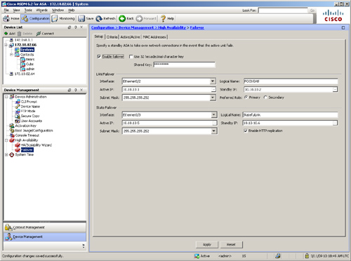
Using ASDM, you can configure device failover by browsing to Configuration > Device Management > High Availability > Failover and selecting the Setup tab. Figure 10-5 illustrates how to configure ASDM for Active/Standby failover.
Figure 10-5 Active/Standby Configuration Through ASDM

Step 1: Select the Failover Link
Decide which interface will be used to send failover control messages. With ASDM, the failover control link interface is selected under the LAN Failover interface drop-down menu. As shown in Figure 10-5, GigabitEthernet0/2 is selected as the failover control link interface and assigned a logical name of FOCtrlIntf.
Use the failover lan interface command followed by the interface name to configure the failover link via the CLI. Example 10-1 shows that the appliances are using GigabitEthernet0/2 as the failover control interface. In this example, the LAN interface is given a name of FOCtrlIntf. However, you can specify any name for this interface.
Example 10-1 Assigning an Interface for LAN-Based Failover
![]()
Note
If an interface already has the nameif statement configured, the security appliance displays an error stating that the interface is already in use. For example:
FO1(config)# failover lan interface FOCtrlIntf GigabitEthernet0/2
Interface already in use
To fix this issue, issue the no nameif command under that interface.
You can use the management interface as the failover link by issuing the clear config interface management0/0 command. This removes the management-only parameter, which then allows the interface to be configured as the failover link.
After the failover lan interface command is configured, the appliance adds a description of LAN Failover Interface under the failover interface configuration, as shown in Example 10-2.
Example 10-2 Description Under the Failover Interface Configuration
![]()
Step 2: Assign Failover IP Addresses
For two security appliances to communicate, the designated failover control interface should be configured with two IP addresses: The first address is used by the active appliance, and the second IP address is owned by the standby appliance. The active unit uses its address to synchronize the running configuration with the standby and to send and receive hello messages.
As shown in Figure 10-5, the active IP address is 10.10.10.1 and the standby IP address 10.10.10.2. The configured subnet mask is 255.255.255.252.
Example 10-3 shows how to configure the IP addresses on the failover control interface, using the CLI.
Example 10-3 Configuring LAN Interface for Failover IP Addresses

After selecting and assigning the active/standby IP on the failover control interface, the next step is to configure the data-passing interfaces for the system and the standby IP addresses. The active appliance uses the system IP addresses, whereas the other appliance uses the standby IP addresses.
In Figure 10-6, the standby IP addresses are configured on the outside, inside, and management interfaces.
Figure 10-6 Standby IP Address Configuration Through ASDM

Example 10-4 shows that the FO1 appliance is using 209.165.200.225, 192.168.10.1, and 172.18.82.64 as the system IP addresses and 209.165.200.226, 192.168.10.2 and 172.18.82.65 as the failover IP addresses on the outside, inside, and management (mgmt) interfaces, respectively.
Example 10-4 Configuring Interface and Failover IP Addresses

Note
If you are not sure whether you are on the active or the standby firewall and want to send commands to the correct unit, you can use the failover exec command, introduced in 8.0(2). For example, if you are logged in to the standby appliance and want to change the hostname on the active appliance to ChicagoASA, issue the following command:
failover exec active hostname ChicagoASA
The failover exec commands are sent over the failover link. It is important that you use a failover key to encrypt traffic, discussed next.
Step 3: Set the Failover Key (Optional)
To secure the failover control messages that are sent between the Cisco ASA appliances, an administrator can optionally specify a shared secret key. It is highly recommended that you specify the shared secret to encrypt and authenticate the failover messages if they are susceptible to interception by unauthorized users. If a failover key is not used, the active appliance sends all information in clear text, including the UDP/TCP states, the user credentials, and the VPN-related information.
Using ASDM, the failover key can be defined under the Shared Key option. Figure 10-5 shows a secret key of cisco123 (obfuscated) is configured to secure the communication between the two devices. Example 10-5 illustrates how to configure a failover shared secret key of cisco123 using the CLI. After you enter the key, it is obfuscated if you view the configuration.
Example 10-5 Configuring Shared Secret Key
![]()
The failover key uses DES or AES, depending on the installed license. It also uses MD5 as the hash to authenticate the message. Therefore, it is important that both appliances use the same cipher license key.
Step 4: Designate the Primary Appliance
The two security appliances send failover control messages through a network cable that has identical ends. Unlike a Cisco PIX Firewall, in which the serial failover cable decides which firewall becomes primary, it is impossible to designate a Cisco ASA as primary based on the Ethernet cable. To resolve the problem of which device should act as primary or secondary, you must designate the primary and secondary status through software configuration.
In ASDM, select the preferred role as either primary or secondary. As illustrated earlier in Figure 10-5, the security appliance is designated as primary. If you prefer to user the CLI, use the failover lan unit command, followed by its role. In Example 10-6, FO1 is designated as the primary failover appliance.
Example 10-6 Designating a Primary Appliance
![]()
Step 5: Enable the Stateful Failover (Optional)
As discussed earlier, the stateful failover feature in the Cisco appliances replicates the state and translation tables from the active unit to the standby unit. In the event of a failure, the standby unit becomes active and begins passing traffic so that data flows are not disrupted. The stateful failover feature requires a network connection between the two units to replicate the connection state information. The appliances can use either a dedicated or the failover control interface to replicate the updates. You can use the failover LAN interface if the stateful updates do not oversubscribe the interface bandwidth. Set up a different interface for stateful failover if you are concerned about possibly oversubscribing the failover control interface.
If you want to set up a stateful link via ASDM, select the physical interface to be used to send stateful packets and specify the active/standby addresses under the Stateful Failover section. As shown in Figure 10-5, GigabitEthernet0/3 is used for stateful failover. The logical name is defined as StatefulLink and is configured with 10.10.10.5 as the active and 10.10.10.6 as the standby IP address with a mask of 255.255.255.252.
Define the stateful interface in the CLI by using the failover link command followed by the name of the interface. Example 10-7 shows GigabitEthernet0/3 is used as the stateful interface, 10.10.10.5 as the active address, and 10.10.10.6 as the standby IP address. The administrator uses StatefulLink as the interface name.
Example 10-7 Configuring Stateful Failover

Note
If you want to use the failover control interface as the stateful link, use the failover link command without the physical interface reference, as follows:
FO1(config)# failover link StatefulLink
The stateful failover does not replicate HTTP-based connections. HTTP connections usually have a short lifetime and therefore are not replicated by default. Additionally, they add considerable load on the security appliance if the amount of HTTP traffic is large in comparison to other traffic. If you want to replicate the HTTP connections to the standby appliance, check the Enable HTTP Replication option in ASDM. You can use failover replication http command via CLI, as illustrated in Example 10-8.
Example 10-8 Configuring HTTP Replication
![]()
Note
Like the failover lan interface command, the appliance adds a description under the stateful link interface and clears any configuration on that interface.
Step 6: Enable Failover Globally
The last step in configuring failover on the primary appliance is to enable failover globally. Select the Enable Failover option in ASDM as shown in Figure 10-5. If you prefer to use the CLI, use the failover command as shown in Example 10-9.
Example 10-9 Enabling Failover Globally
![]()
Note
If you turn off failover on the active appliance by using the no failover command, the standby appliance goes in the pseudo-failover state.
Step 7: Configure Failover on the Secondary Appliance
In the Cisco failover feature, there is no need to manually configure the secondary appliance. Instead, you just need to configure some basic information about failover. After that, the primary/active appliance starts synchronizing its configuration. The bootstrap configuration includes the following six configuration parameters:
• Enabling the failover control interface
• Failover designation as secondary
• Failover link interface
• Same failover interface IP addresses
• Same failover shared key
• Failover enable
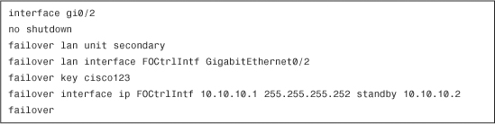
Example 10-10 shows the bootstrap configuration of the secondary appliance needed in LAN-based failover.
Example 10-10 Bootstrap Configuration of the Secondary Appliance
Note
After failover is enabled on both appliances, their running configuration is identical except for the failover lan unit command.
Active/Active Failover Configuration
The configuration of the Active/Active failover feature in the Cisco ASA is broken down into 11 steps:
Step 1. Select the failover link.
Step 2. Assign failover interface IP addresses.
Step 3. Set the failover key (optional).
Step 4. Designate the primary appliance.
Step 5. Enable the stateful failover (optional).
Step 6. Set up failover groups.
Step 7. Assign failover-group membership.
Step 8. Assign interface IP addresses.
Step 9. Set up asymmetric routing (optional).
Step 10. Enable failover globally.
Step 11. Configure failover on the secondary appliance.
Figure 10-2 is used throughout this section to demonstrate how to configure Active/Active failover functionality on the Cisco ASA.
Using ASDM, you can configure device failover by browsing to Configuration > System Context > Device Management > High Availability > Failover and selecting the Setup tab. Figure 10-7 is used throughout this section to illustrate how to configure ASDM for Active/Active failover.
Figure 10-7 Active/Active Configuration Through ASDM
Step 1: Select the Failover Link
Decide which interface will be used to send failover control messages. The failover control link interface in ASDM is selected under the LAN Failover interface drop-down menu. As shown in Figure 10-7, GigabitEthernet0/2 is selected as the failover control link interface and assigned a logical name of FOCtrlIntf.
Example 10-11 illustrates how to configure GigabitEthernet0/2 as the LAN failover interface in the appliance when you’re using the CLI. In this example, the LAN interface is given a name of FOCtrlIntf.
Example 10-11 Assigning an Interface for LAN-based Failover
![]()
Step 2: Assign Failover Interface IP Addresses
After selecting the failover control interface, configure the active/standby IP addresses. As shown in Figure 10-7 and Example 10-12, the active IP address is 10.10.10.1 and the standby IP address is 10.10.10.2. The configured subnet mask is 255.255.255.252.
Example 10-12 Configuring LAN Interface for Failover IP Addresses

Step 3: Set the Failover Key
To protect the failover control messages sent between two Cisco ASAs, you can optionally specify a shared secret key. Figure 10-7 shows a secret key of cisco123 (obfuscated) is configured to secure the communication between the two devices. Example 10-13 illustrates the same via the CLI.
Example 10-13 Configuring Shared Secret Key
![]()
Step 4: Designate the Primary Appliance
You must designate one appliance as primary and the other as secondary. As illustrated in Figure 10-7 and Example 10-14, the security appliance is designated as the primary failover appliance.
Example 10-14 Designating a Primary Appliance
![]()
Step 5: Enable the Stateful Failover
To implement Active/Active failover, the appliances use a stateful failover link to send continuous connection table updates. The asymmetric routing also heavily depends on the stateful failover link. To define a stateful link via ASDM, select the physical interface to be used to send stateful packets and specify the active/standby addresses under the Stateful Failover section. As shown in Figure 10-7 and Example 10-15, GigabitEthernet0/3 is used for stateful failover. The logical name is defined as StatefulLink and is configured with 10.10.10.5 as the active and 10.10.10.6 as the standby IP address with a mask of 255.255.255.252.
Example 10-15 Configuring Stateful Failover

Step 6: Set Up Failover Groups
As mentioned earlier, the Active/Active failover is available only if you have multiple security contexts configured on a security appliance. Let us say you have two security contexts configured on the security appliance: Bears and Cubs. An administrator can designate the first security appliance to be active for the Bears context while backing up Cubs. Similarly, the other security appliance can act as an active unit for Cubs while backing up Bears. This Active/Active failover is achieved by using the failover group command via the CLI:
failover group group#
Example 10-16 shows all the options that can be defined within a failover group. The appliance is configured to use failover with a group ID of 1. This group ID is later used to link the failover group to a context.
Example 10-16 Failover Group Submenu Options

Note
You can configure only a group ID of 1 or 2 in the current implementation. If you are using more than two contexts, then you must assign each context to one of the failover groups.
The interface-policy, polltime, and mac parameters are discussed extensively in the upcoming section, “Optional Failover Commands.”
The preempt option instructs the security appliance to immediately become the active unit for that group if it has a higher priority. This typically occurs when a security appliance goes through the reboot process. The priority is determined when the group is configured with the primary or the secondary options. Primary means that this unit has a higher priority and should be the active appliance for the group. Secondary, on the other hand, assigns a lower priority and prefers the other unit to act as an active device for that group.
The replication option is useful if you want the active appliance to send updates about the HTTP state and connection entries to the standby appliance.
Note
You must enable HTTP inspection to allow the HTTP traffic to work in the Active/Active setup with asymmetric routing.
To define a failover group with ASDM, navigate to Configuration > System > Connect > Device Management > High Availability > Failover > Active/Active tab and click Add. If you don’t have a previously defined failover group, then the very first group is defined as failover group 1. In Figure 10-8, a new group (group 1) is being added. This group is set up to act as a primary and to preempt the failover state in case it is rebooted. However, it waits 15 seconds before initializing the preempt process. After 15 seconds of the last failover occurrence, the failover Group 1 becomes active. Additionally, when it is acting as the active device, it sends updates regarding the HTTP connections to the other appliance.
Figure 10-8 Failover Group Configuration Through ASDM

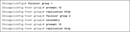
Example 10-17 shows the Chicago FO1 appliance is configured for two failover groups. Group 1 is set up to act as a primary failover device (the default option of a group) and to preempt the failover state after 15 seconds. Group 2, on the other hand, is set up to be in secondary mode. It also tries to preempt the state after it completes the boot sequence.
Example 10-17 Configuring Failover Groups
Note
The admin context is always a part of failover group 1. If you don’t explicitly map a context to a failover group, then it is automatically assigned to group 1.
Note
The http replication command in the failover group overrides the global http replication command.
Step 7: Assign Failover Group Membership
After setting up the failover groups, map these groups to the appropriate security contexts. In Figure 10-4, the administrator wants to designate FO1 as the active appliance for Cubs and standby for Bears, and wants to designate FO2 as the active appliance for Bears and standby for Cubs. Figure 10-9 illustrates that failover group 1 is mapped to the Bears context.
Figure 10-9 Failover Group Assignment Through ASDM
Example 10-18 illustrates how you achieve assignment of the failover group to a context by using the join-failover-group command. Context Cubs is a part of failover group 1, whereas context Bears is a member of failover group 2.
Example 10-18 Failover Group Assignment

With this configuration, Cubs context is active on the FO1 device, and the Bears context is active on FO2.
Step 8: Assign Interface IP Addresses
For all the interfaces, except the failover link and stateful link interface, the system and standby IP addresses are configured in the security contexts. As shown in Figure 10-10, Bears is configured to use 209.165.200.225 and 209.165.200.226 as the system and standby IP addresses, respectively, on the outside interface. It is also configured to use 192.168.10.1 and 192.168.10.2 as the system and standby IP address, respectively, on the inside interface.
Figure 10-10 Interface Address Assignment Through ASDM

Example 10-19 presents the equivalent configuration of Figure 10-10 in the CLI format.
Example 10-19 Configuration of System and Standby IP Addresses

Step 9: Set Up Asymmetric Routing (Optional)
As discussed earlier, Cisco ASA enables you to set up asymmetric routing to ensure that return traffic can be forwarded to the active device in the Active/Active deployment. When it is enabled on an interface and the incoming traffic reaches a context that is active on the other security appliance and does not have the associated flow, the security appliance
• Reclassifies the incoming traffic to another interface of the same asr-group after determining the flow.
• Forwards the packet to the active unit for further processing.
To enable asymmetric routing via ASDM, browse to Configuration > <Context Name> > Connect > Device Setup > Routing > ASR Group and select an asr group on the interface. In most implementations, it is the outside interface.
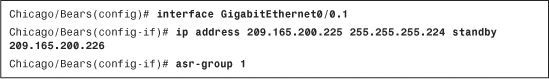
Use the asr-group interface command to enable asymmetric routing on the security appliances via the CLI. In Example 10-20, the GigabitEthernet0/0.1 interface is configured for asymmetric routing and it belongs to asr-group 1.
Example 10-20 Configuring Asymmetric Routing
Step 10: Enable Failover Globally
Enable failover globally on the primary appliance by selecting the Enable Failover option in ASDM as shown in Figure 10-7. Example 10-21 shows how to enable failover on the Chicago appliance.
Example 10-21 Enabling Failover Globally
![]()
Step 11: Configure Failover on the Secondary Appliance
In the Cisco failover feature, there is no need to manually configure the secondary appliance. Instead, you just need to configure some basic information about the failover. After that, the primary appliance starts synchronizing its configuration to the secondary appliance. The bootstrap configuration includes the following six configuration parameters:
• Enabling the failover control interface
• Failover designation as Secondary
• Failover link interface
• Same failover interface IP address
• Failover shared key (optional)
• Failover enable
ASDM Failover Wizard Configuration
The easiest way to define a failover between two devices is by following the HA/Failover wizard. Launch the failover wizard by navigating to Configuration > Device Management > High Availability > HA/Scalability Wizard, or clicking Wizards in the toolbar and then selecting High Availability and Scalability Wizard.
ASDM launches the failover wizard with the option to choose a Failover Configuration Type. You can define one of the following failover types:
• Active/Active Failover
• Active/Standby Failover
• VPN Cluster Load balancing
Note
VPN Cluster load balancing is discussed in Chapter 17.
Following are the steps for defining an Active/Active failover connection with the wizard. Configuration of Active/Standby failover via ASDM wizard is very similar.
Step 1. Select the Configure Active/Active Failover radio button.
To define an Active/Active failover, your ASDM must have connectivity to both failover devices. After you select Active/Active failover, click Next to go to Step 2.
Step 2. Specify peer information.
ASDM prompts you to specify the IP address of the secondary security appliance so that it can conduct all the checks and appropriate failover tests before it configures Active/Active failover. Click Next after all tests have passed.
Step 3. Select the failover group.
If you have two customer contexts (Bears and Cubs), then specify failover group 1 to Bears and failover group 2 to Cubs. Click Next to proceed to the next step.
Step 4. Specify the failover attributes.
Next, ASDM prompts you to specify the interface you want to use as a failover link control interface. Select GigabitEthernet0/3 as the LAN Failover and assign FOCtrlIntf as its logical name. Define the primary failover interface IP address as 10.10.10.1 and the standby address as 10.10.10.2. Specify the subnet mask of 255.255.255.252 and the shared key as cisco123 (obfuscated). Click Next when you are finished.
Step 5. Specify the stateful link attributes
If you also want to use the failover link interface as the stateful link interface, select Use the LAN Link as the State Link. If you would rather use a different physical interface for stateful failover, select Configure Separate Stateful Failover Interface and select an unused interface from the drop-down menu. Also specify the active and standby IP addresses for the stateful link interface.
Step 6. Define standby addresses.
In this next step, ASDM shows all the predefined contexts, the allocated interfaces, and their assigned system IP addresses. You must define the standby IP address to each interface to complete the Active/Active configuration.
Step 7. Verify failover configuration.
ASDM shows the summary of the failover configuration. If everything looks accurate, click Finish. ASDM pushes the failover commands to the primary firewall first and then to the secondary firewall.
Interface Level Redundancy Configuration
ASDM enables you to define a redundant interface for both single-mode and multiple-mode firewalls.
Interface-Level Redundancy in Single-Mode Firewall
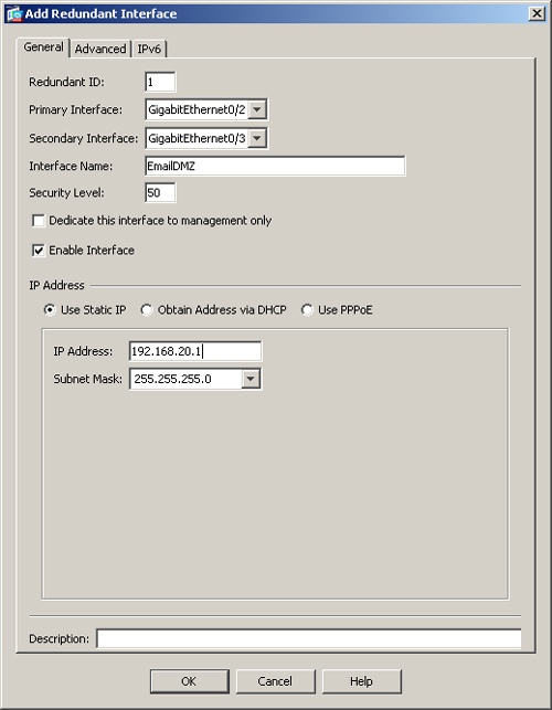
You can configure interface-level redundancy through ASDM by navigating to Configuration > Device Setup > Interfaces > Add > Redundant Interface. ASDM opens a new window where you can bind up to two physical interfaces to a redundant logical interface. As illustrated in Figure 10-11, a redundant interface with an ID of 1 is being defined. The administrator has grouped GigabitEthernet0/2 and GigabitEthernet0/3 as the primary and secondary member interfaces. The interface name (nameif) is EmailDMZ and the security level of 50 is defined. A static IP address of 192.168.20.1 with a mask of 255.255.255.0 is also configured.
Figure 10-11 Redundant Interface Definition Through ASDM
Example 10-22 presents the equivalent configuration of Figure 10-11 in the CLI format.
Example 10-22 Defining a Redundant Interface

Interface-Level Redundancy in Multiple-Mode Firewall
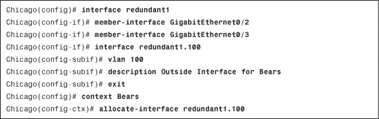
In a multiple-mode firewall, define a redundant interface by navigating to Configuration > System > Connect > Device Setup > Interfaces > Add > Redundant Interface. ASDM opens a new window where you can bind up to two physical interfaces to a redundant logical interface and add an interface description. ASDM does not allow you to configure any other attribute such as the interface name or a security level. In Example 10-23, the administrator has grouped GigabitEthernet0/2 and GigabitEthernet0/3 as the primary and secondary member interfaces under interface Redundant1.
Example 10-23 Defining a Redundant Interface in Multimode firewall

After a redundant interface has been configured in a multimode firewall, you can either allocate that interface to a security context or you can create subinterfaces and then allocate those subinterfaces to a security context. As shown in Example 10-24, a sub-interface has been defined with a VLAN ID of 100. It is then assigned to a security context called Bears.
Example 10-24 Defining a Redundant Subinterface in Multimode Firewall
Optional Failover Commands
The security appliance allows you to optionally tweak many default failover parameters to optimize device redundancy in your network. These parameters include
• Specifying failover MAC addresses
• Configuring interface policy
• Monitoring failover interfaces
Specifying Failover MAC Addresses
In Active/Standby failover, the active device uses the primary unit’s MAC addresses. In the event of a failover, the secondary appliance becomes active and takes over the primary unit’s MAC addresses, whereas the active device (now standby) takes over the standby unit’s MAC addresses. After the standby appliance becomes active, it sends out a gratuitous ARP on the network. A gratuitous ARP is an ARP request that the appliance sends out on the Ethernet networks with the source and destination IP addresses of the active IP addresses. The destination MAC address is the Ethernet broadcast address, ffff.ffff.ffff. All devices on the Ethernet segment process this broadcast frame and update their ARP table with this information. Using gratuitous ARP, the Layer 2 devices, including bridges and switches, also update the Content Addressable Memory (CAM) table with the MAC address and the updated switch port information.
When a secondary appliance boots up before the primary appliance, it uses its physical MAC addresses as active Layer 2 addresses. However, when the primary appliance boots up, the secondary swaps the MAC addresses and uses the primary appliance’s physical MAC addresses as active. Therefore, the use of a virtual MAC address is recommended to avoid network disruptions. With the virtual MAC address, the appliances do not need to swap the MAC address.
Specifying MAC Addresses in Active/Standby Failover
A MAC address can be assigned at multiple locations on the security appliances. If multiple virtual MAC addresses are defined in an Active/Standby failover deployment, then the security appliances can follow a priority list:
Step 1. Use of a virtual active and standby MAC address at the physical, logical or subinterface.
Step 2. Use of failover mac address command in the global configuration mode.
Step 3. Use of an interface’s burned-in MAC addresses, if no virtual mac address is defined.
Using ASDM, assign a virtual MAC address to an interface by navigating to Configuration > Device Management > High Availability > Failover > MAC addresses tab and clicking Add, if you have an Active/Standby firewall. ASDM prompts you to select an interface whose mac address you want to change and then assign an active and a standby MAC address. As shown in Figure 10-12, the primary active appliance is being configured to use 0000.1111.2222 as the active MAC address and 0000.1111.2223 as the standby MAC address on the GigabitEthernet0/2 interface on an Active/Standby firewall.
Figure 10-12 Assigning Virtual MAC Addresses Through ASDM

In Example 10-25, the administrator assigns 0000.1111.2222 as the active MAC address and 0000.1111.2223 as the standby MAC address on the GigabitEthernet0/2 interface via the CLI on an Active/Standby firewall.
Example 10-25 Defining System and Standby MAC Addresses for Active/Standby

Specifying MAC Addresses in Active/Active Failover
As mentioned earlier, a MAC address can be assigned at multiple locations on the security appliances. If multiple virtual MAC addresses are defined in an Active/Active failover deployment, then the security appliances can follow a priority list as follows:
Step 1. Use of a virtual active and standby MAC address at the physical, logical or subinterface
Step 2. Use of mac address command in the failover group configuration mode.
Step 3. Use of the mac address auto command in the system execution space. This auto-generates the virtual active and standby addresses. Consult Chapter 8 for more information about the mac address auto command.
Step 4. If no virtual mac address is defined, the security appliance uses the physical interface MAC address.
In Active/Active failover, you can assign unique virtual MAC addresses to each interface under each security context. You can change the MAC address from its default by navigating to Configuration > {Security Context} > Connect > Device Setup > Interfaces > {Interface} > Edit > Advanced tab and specifying the active and standby MAC address to that interface.
Using the CLI, assign a unique MAC address by issuing the mac address command to an interface in a specific context. In Example 10-26, the MAC address is changed to 0000.1111.2222 for the active system and 0000.1111.2223 for the standby system GigabitEthernet0/0.100 in the Bears context.
Example 10-26 Assigning System and Standby MAC Addresses for Active/Active

Note
In Active/Active setup, the failover mac address command has no effect if issued in the global configuration menu.
Chicago(config)# failover mac address GigabitEthernet0/0 0000.1111.2222
0000.1111.2223
WARNING: command has no effect for active/active failover
Configuring Interface Policy
The appliance monitors the status of all the interfaces. If one of the interfaces fails to respond, failover occurs and the standby appliance takes over the connections. However, if you prefer the system to fail over when two or more interfaces fail to respond, then you can modify this default behavior by changing the interface failover policy. If you use ASDM, navigate to Configuration > Device Management > High Availability > Failover > Criteria tab and specify the number of monitored interfaces that must fail before triggering a failover under “Interface Policy.” As illustrated in Figure 10-13, the interface policy is changed to 2.
Figure 10-13 Changing Interface Policy Through ASDM

Using the CLI, you can use the failover interface-policy command for Active/Standby failover, as shown in Example 10-27, to change the interface policy from 1 to 2.
Example 10-27 failover interface-policy Command in Active/Standby Failover
![]()
In the Active/Active failover, the interface policy is applied under the Failover Group Sub-configuration menu.
Managing Failover Timers
The Cisco ASAs, by default, send periodic keepalive (hello) packets to check the status of the peer failover unit. If the standby appliance does not receive acknowledgments for the keepalive packet it sends out, it initiates a failover only if it deems itself healthier than the current active. The appliances support two types of failover hello messages:
• Unit—Sent every second to monitor the status of the failover control interface
• Interface—Sent every 15 seconds to monitor the health of the physical interfaces
You can, however, change this default behavior to send keepalive (hello) packets based on custom timeouts. For example, you can send keepalive packets every 500 milliseconds for 3 seconds (hold-time timer) to monitor the status of the failover interface. The security appliances send out hello packets to the failover mate every 500 milliseconds. If the unit interface hold-time is reached (which is 3 seconds) and no response has been heard, the failover process is initiated. The results of the interface test dictate whether the secondary appliance needs to initiate a failover.
Using ASDM, navigate to Configuration > Device Management > High Availability > Failover > Criteria tab and specify the failover timers under the Failover Poll Times section. As shown earlier in Figure 10-13, the security appliance is configured to send keepalive packets every 500 msec for 3 seconds. The interface polltime is changed to 6 seconds so that hello packets are sent every 6 seconds for 30 seconds before the interface test is initiated. Example 10-28 shows the same policy using the CLI.
Example 10-28 Failover Polltime in Active/Standby Failover
![]()
If you use the Active/Active failover, the unit failover timers are changed in the system configuration menu, whereas the interface timers are changed in the failover group policy, as shown in Example 10-29.
Example 10-29 Failover Polltime in Active/Active Failover

Monitoring Failover Interfaces
When an appliance is configured for failover, whether Active/Standby or Active/Active, it monitors the status of all the main physical interfaces that have a nameif and an IP address configured. If you do not want the failover process to monitor a particular interface, such as a dummy or test interface, for example, you can disable monitoring for that interface.
Interface monitoring is disabled, by default, on all the subinterfaces until you explicitly enable it. For example, if you have subinterfaces defined in an Active/Active scenario, and those interfaces are allocated to specific security contexts, then the security appliance does not send keepalive packets on those subinterfaces. If you want instead to enable failover monitoring on those subinterfaces, you must enable interface monitoring on those interfaces.
Under ASDM, you can enable or disable interface monitoring by navigating to following locations:
• Configuration > Device Management > High Availability > Failover > Interfaces tab, if using single-mode firewall
• Configuration > {Context Name} > Connect > Device Management > Failover, if using multiple-mode firewall
Using the CLI, you can use the no monitor-interface command to disable interface monitoring and monitor-interface to enable monitoring on that interface. Example 10-30 illustrates how to enable failover monitoring on the EmailDMZ interface.
Example 10-30 Enabling Failover Interface Monitoring
![]()
Zero-Downtime Software Upgrade
Certain firewalls are not compatible when they are deployed in failover and are running different software versions. The Cisco security appliance allows you to run failover even if the appliances are running different versions of images. This is useful when the security appliances need to be upgraded to a newer maintenance release without any service disruption. Follow these steps to complete the image-upgrade process without any network outage:
Note
Stateful failover is mandatory for a zero-downtime software upgrade.
Step 1. Upload the new image to both security appliances.
You can use any of the supported transfer methods to upload the new maintenance image to both security appliances. In the following example, the administrator uploads the 8.2(2) system image from a TFTP server located at 172.18.108.26 to the system flash:

After the image is uploaded, use the show flash command to verify whether the image resides in the disk:
![]()
Note
The zero-downtime software upgrade process can be used to upgrade the maintenance image on the security appliances, such as from 8.2(1) to 8.2(3). You can also upgrade from a minor release to the next minor release, such as from 8.1(1) to 8.2(1). Additionally, you can also upgrade from the last major release to the first version of the next major release, such as from 8.1(2) to 8.2(1). The failover is disabled if the security appliances run any other release that does not meet the criteria. That means you cannot run 7.0(2) on one security appliance and 8.2(1) on the other.
Step 2. Set boot parameters.
After an image is uploaded, log in to the active appliance and set the system boot parameters to instruct the security appliance to load the newly uploaded image on the next reboot. Here, the administrator configures the active security appliance to load the asa822-k8.bin image on the next reboot:
Chicago(config)# boot system disk0:/asa822-k8.bin
Chicago(config)# write mem
Note
The commands entered on the active security appliance are synchronized with the standby unit.
Step 3. Reboot the standby appliance.
After the new image is uploaded, log in to the standby security appliance and check failover status by using the show failover command. Verify that the security appliance is in the standby state. Here, the secondary security appliance is in standby mode:

Use the reload command to reboot the standby security appliance:
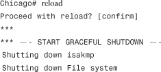
After the standby appliance comes online, check the version of the system image. If it is running the newly uploaded image, wait for five minutes so that the connections are replicated and then force the failover so that the standby security appliance becomes active and takes over the connections. Issue the failover active command to switch failover, as follows:

Step 5. Reboot the standby appliance.
Reboot the standby appliance (which was active before forced failover) so that it can also load the updated image. Use the reload command on the standby appliance to initiate the reboot process.
Step 6. Force failover (optional).
After the standby firewall comes online, you can optionally issue the failover active command to switch the failover state.
Note
If the standby security appliance is set up with the preempt option in Active/Active mode, it automatically becomes active after coming online.
Deployment Scenarios
The failover feature is useful in deployments where redundancy is required to ensure near 100 percent uptime of the network devices. Although the failover feature can be deployed in many ways, we cover only two design scenarios for ease of understanding:
• Active/Standby failover in single mode
• Active/Active failover in multiple security contexts
Note
The design scenarios discussed in this section should be used solely to reinforce learning. They should be used only for reference purposes.
Active/Standby Failover in Single Mode
In the first deployment scenario, SecureMe, Inc., is looking to implement failover at its Chicago location. It has purchased two Cisco ASA 5580 appliances for this purpose. The company requires implementation of the stateful failover feature to ensure that all the active connections (excluding the HTTP connections) are replicated to the standby unit in case there is a failure on the primary unit. SecureMe requires the standby appliance to become active if the primary appliance does not acknowledge the keepalive packets for three seconds. Additionally, SecureMe wants to implement interface redundancy for all its interfaces, including inside, outside, failover control, and stateful link. Figure 10-14 illustrates a proposed design for Active/Standby failover.
Figure 10-14 Deployment Scenario Using Active/Standby Failover
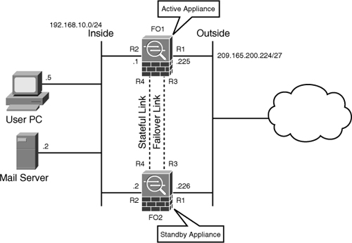
Configuration Steps Through ASDM
The relevant configuration through ASDM is discussed here. These configuration steps assume that you have IP connectivity from the ASDM client to the management IP address of the security appliances. The management IP address of the primary security appliance is 172.18.82.64 and the IP address of the secondary security appliance is 172.18.82.65. The connection and translation tables are constantly replicated to the secondary appliance over a dedicated stateful link interface.
Step 1. Navigate to Configuration > Device Setup > Interfaces > Add and click the Redundant Interfaces. Configure the following parameters:
• Redundant ID: 1
• Primary Interface: GigabitEthernet3/0
• Secondary Interface: GigabitEthernet4/0
• Security Level: 0
• IP Address: 209.165.200.225
• Subnet Mask: 255.255.255.248
• Leave all other options to default. Click OK and Apply when you are finished.
Step 2. Navigate to Configuration > Device Setup > Interfaces > Add and click the Redundant Interfaces. Configure the following parameters:
• Redundant ID: 2
• Primary Interface: GigabitEthernet3/1
• Secondary Interface: GigabitEthernet4/1
• Interface Name: inside
• Security Level: 100
• IP Address: 192.168.10.1
• Subnet Mask: 255.255.255.0
• Leave all other options to default. Click OK and Apply when you are finished.
Step 3. Navigate to Configuration > Device Setup > Interfaces > Add and click the Redundant Interfaces. Configure the following parameters:
• Redundant ID: 3
• Primary Interface: GigabitEthernet3/2
• Secondary Interface: GigabitEthernet4/2
• Leave all other options to default. Click OK and Apply when you are finished.
Step 4. Navigate to Configuration > Device Setup > Interfaces > Add and click the Redundant Interfaces. Configure the following parameters:
• Redundant ID: 4
• Primary Interface: GigabitEthernet3/3
• Secondary Interface: GigabitEthernet4/3
• Leave all other options to default. Click OK and Apply when you are finished.
Step 5. Navigate to Configuration > Device Management > High Availability > Failover and click the Setup tab. Configure the following parameters:
• Enable Failover box: Checked
• Shared Key: cisco123
• LAN Failover Interface: Redundant3
• LAN Failover Logical Name: FOCtrlIntf
• LAN Failover Active IP: 10.10.10.1
• LAN Failover Standby IP: 10.10.10.2
• LAN Failover Active IP: 255.255.255.252
• Preferred Role: Primary
• State Failover Interface: Redundant4
• State Failover Logical Name: StatefulLink
• State Failover Active IP: 10.10.10.5
• State Failover Standby IP: 10.10.10.6
• State Failover Active IP: 255.255.255.252
• Enable HTTP Replication: Not checked.
Step 6. Navigate to Configuration > Device Management > High Availability > Failover and click the Interfaces tab. Configure the following parameters:
• Inside Interface Standby IP Address: 192.168.10.2
• Outside Interface Standby IP Address: 209.165.200.226
Step 7. Navigate to Configuration > Device Management > High Availability > Failover and click the Criteria tab. Configure the following parameters:
• Failover Poll Times Unit Failover: 500 milliseconds
• Failover Poll Times Unit Hold Time: 3 seconds
• Leave all other options to default. Click Apply when you are finished. ASDM prompts you to specify the IP address of the secondary appliance so that it can configure the necessary commands.
Configuration Steps Through CLI
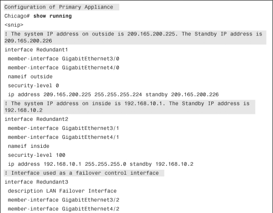
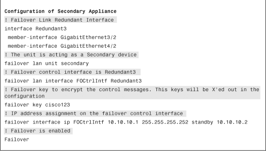
Example 10-31 shows the relevant configuration of the primary appliance and the bootstrap configuration of the secondary appliance. The primary appliance, being the active unit, synchronizes the entire running configuration to the secondary appliance.
Example 10-31 Cisco ASA Configuration Using Active/Standby Failover

Active/Active Failover in Multiple Security Contexts
SecureMe’s managed services group is currently using a Cisco ASA 5540 appliance as the Internet gateway for its customers, Bears and Cubs. SecureMe’s management is looking to implement an Active/Active failover solution where it can make Bears active on one appliance and Cubs on the other. It has purchased another Cisco ASA 5540 appliance to implement this solution. The primary appliance is to act as an active unit for Bears, the other appliance is to act as an active unit for Cubs, and both are to back up each other in the event of a failure. Figure 10-15 illustrates a proposed design to meet these requirements.
Figure 10-15 Deployment Scenario Using Active/Active Failover
When both appliances are active and passing traffic, the administrator also wants these devices to send connection and translation table updates to one another, using the failover control interface.
Configuration Steps Through ASDM
The relevant configuration through ASDM is discussed here. These configuration steps assume that you have IP connectivity from the ASDM client to the management IP address of the security appliances. The management IP address of the primary security appliance is 172.18.82.66 and the IP address of the secondary security appliance is 172.18.82.67.
Step 1. Navigate to Configuration > System > Connect > Device Management > High Availability > Failover and click the Setup tab. Configure the following parameters:
• Enable Failover box: Checked
• LAN Failover Interface: GigabitEthernet0/2
• LAN Failover Logical Name: FOCtrlIntf
• LAN Failover Active IP: 10.10.10.1
• LAN Failover Standby IP: 10.10.10.2
• LAN Failover Active IP: 255.255.255.252
• Preferred Role: Primary
• State Failover Interface: GigabitEthernet0/2
• Enable HTTP Replication: Not checked.
Step 2. Navigate to Configuration > System > Connect > Device Management > High Availability > Failover, click the Active/Active tab, and then Add. Configure the following parameters:
• Preferred Role: Primary
• Preempt after booting with optional delay of: 15 seconds
• Enable HTTP Replication: Checked, select OK.
Step 3. Navigate to Configuration > System > Connect > Device Management > High Availability > Failover, click the Active/Active tab and then Add. Configure the following parameters:
• Preferred Role: Secondary
• Preempt after booting with optional delay of: 15 seconds
• Enable HTTP Replication: Checked. Click OK and then Apply when you are finished. ASDM prompts you to specify the IP address of the secondary appliance so that it can configure the necessary commands.
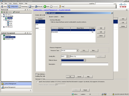
Step 4. Navigate to Configuration > System > Connect > Context Management > Security Contexts, select Bears and then click Edit. Under Failover Group, select 1.
Step 5. Navigate to Configuration > System > Connect > Context Management > Security Contexts, select Cubs, and then click Edit. Under Failover Group, select 2 and Apply.
Step 6. Navigate to Configuration > Bears > Connect > Device Management > High Availability > Failover and specify the standby IP addresses to all interfaces. Additionally, select the Monitored option under all interfaces.
Step 7. Navigate to Configuration > Bears > Connect > Device Setup > ASR Routing > ASR Group and select ASR group 1 for the outside interface.
Step 8. Navigate to Configuration > Cubs > Connect > Device Management > High Availability > Failover and specify the standby IP addresses to all interfaces. Additionally, select the Monitored option under all interfaces.
Step 9. Navigate to Configuration > Cubs > Connect > Device Setup > ASR Routing > ASR Group and select ASR group 1 for the outside interface.
Step 10. Navigate to Configuration > admin > Connect > Device Management > High Availability > Failover and specify the standby IP addresses to all interfaces.
Configuration Steps Through CLI
Example 10-32 shows relevant configuration of the primary appliance and the bootstrap configuration of the secondary appliance. The primary appliance synchronizes the entire running configuration to the secondary appliance. The administrator has implemented the asymmetric routing feature to avoid routing issues if packets arrive on the other active appliance.
Example 10-32 Cisco ASA Configuration Using Active/Active Failover in Multiple Security Contexts


Monitoring and Troubleshooting Failovers
The Cisco ASA has a rich set of show and debug commands that are useful to monitor the status of the standby appliance. These commands are particularly important in isolating a problem if something behaves unexpectedly. The necessary show and debug commands that are used to manage Active/Standby and Active/Active failover in the appliance are discussed in this section. Deployment Scenario 1 is used for references in this section.
Monitoring
After the primary appliance is configured for failover, verify that the appliance recognizes failover as enabled. You can check the status of an appliance’s failover by using the show failover command, as shown in Example 10-33.
Example 10-33 Output of show failover to Check Whether Failover Is Enabled

After the secondary appliance is configured for bootstrap configuration, the primary appliance synchronizes the running configuration to the secondary appliance, as shown in Example 10-34.
Example 10-34 Configuration Replication
![]()
The secondary appliance loads the running configuration and becomes standby to monitor the status of the primary appliance. In Example 10-35, the secondary appliance is in standby with its current IP addresses set as the standby addresses.
Example 10-35 Output of show ip

You can check the failover or standby IP addresses by using the show failover command. If stateful failover is set up, show failover also displays the stateful failover statistics, along with the number of updates it has received and transmitted. Example 10-36 shows the output of show failover with the system and standby IP addresses and information about stateful failover.
Example 10-36 Output of show failover in Active/Standby Deployment


Note
The xerr and rerr are transmit and receive errors that occur when the appliances send stateful information to each other. Stateful failover is enacted as a best effort and there will be times when errors increment because of congestion and other reasons.
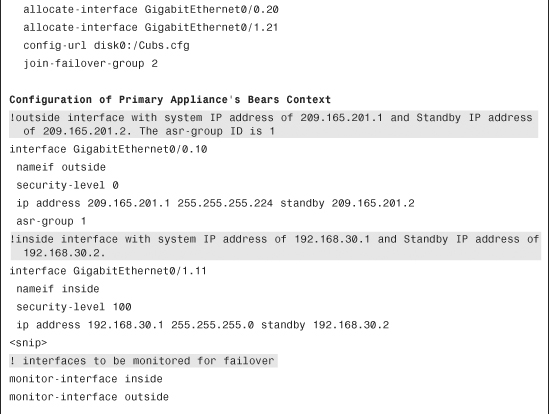
In the Active/Active failover, the failover can be verified either from the system execution space or from the security context. The failover information from the security context displays the current status of the context, along with the system and current IP addresses. It also displays the stateful failover statistics, as shown in Example 10-37.
Example 10-37 Output of show failover in Active/Active Deployment
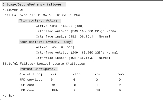
If failover occurs and you do not know why it occurred, issue the show failover state command, as shown in Example 10-38. The security appliance provides you a reason, such as interface failure, that caused failover to occur.
Example 10-38 Output of show failover state
Troubleshooting
If the failover is properly set up, but the security appliances are not synchronizing the configuration, verify the status of security appliances. If the status of the other security appliance is failed, as shown in Example 10-39, the failover is not operational.
Example 10-39 Failover Failure

To resolve this issue, check the following settings:
• The failover cable is physically connected between the security appliances. If they are connected via a Layer 2 switch, ensure that both failover control interfaces belong to the same VLAN.
• Failover is enabled on both security appliances.
• Failover configuration is valid on both security appliances.
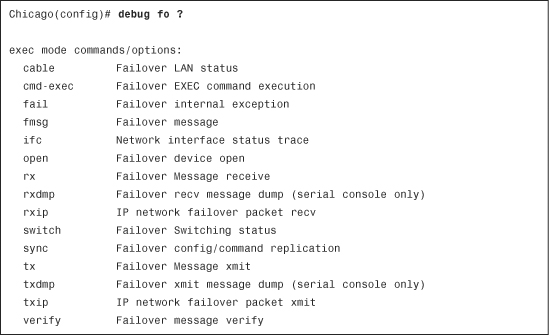
The security appliance supports a number of debug commands for troubleshooting purposes. Use the debug fo commands as shown in Example 10-40 to enable the failover debug messages.
Caution
The failover debug commands produce a lot of output. Do not enable these debugs without consulting a TAC engineer.
Example 10-40 Available Failover Debugs
To troubleshoot issues related to failover timing, use the debug fo rxip and debug fo txip commands to determine whether the packets are being exchanged according to the configured polltimes. As illustrated in Example 10-41, the FHELLO (failover hello) packets are received on all the configured interfaces.
Example 10-41 Output of debug fo rxip and debug fo txip

It is recommended that you enable logging of failover messages to either an internal buffer or an external syslog server to avoid overwhelming the console or remote administrative session. In Example 10-42, the administrator sets up buffer logging for the failover (ha) logging class, represented as fo_logging, with a logging buffer size of 20,000 bytes.
Example 10-42 Enable Failover Logging

After enabling failover logging, the administrator can use the show logging command. In Example 10-43, the primary security appliance is changing its role from active to standby. The failover was initiated by the secondary appliance. The physical interfaces change their state from waiting to normal.
Example 10-43 Output of show logging
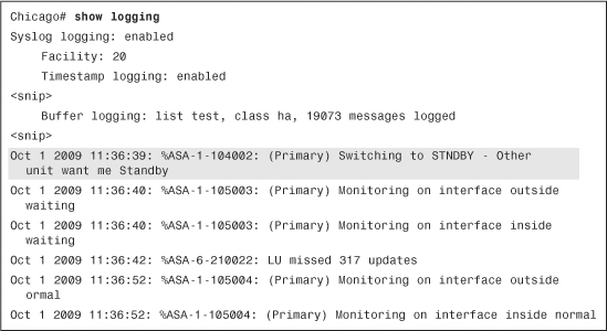
If the standby firewall determines that the replication of configuration from the active appliance is incomplete or the active appliance has partial configuration, it goes through a reboot process. This is necessary so that the standby device with the partial configuration does not become an active device in case of a failure on the current active device. Example 10-44 shows the error message you will see on the console connection of the standby device when it is about to reboot. After it completes the reboot process, the active device sends the complete configuration to the standby device.
Example 10-44 Standby Firewall Rebooting Due to Partial Configuration

Summary
The failover feature in the Cisco security appliance is designed to allow network administrators to achieve near 100 percent uptime for their network devices. The robust appliance operating system allows administrators to have two appliances in the active state to pass traffic. It also allows the appliances to support asymmetric routing to load-balance traffic across multiple service providers. This chapter covered extensive show and debug commands to assist in troubleshooting simple and complicated failover deployments.