Chapter 17. IPSec Remote-Access VPNs
Remote-access VPN services provide a way to connect home and mobile users to the corporate network. Until a decade ago, the only way to provide this service was through dialup connections using analog modems. Corporations had to maintain a huge pool of modems and access servers to accommodate remote users. Additionally, they were billed for providing toll-free and long-distance phone services. With the rapid growth of Internet technologies, more and more dialup mobile users are migrating to broadband DSL and cable-modem connections. As a result, corporations moved these dialup users to remote-access VPNs for faster communication.
There are many remote-access VPN protocols available to provide secure network access. The commonly used ones include the following:
• Point-to-Point Tunneling Protocol (PPTP)
• Layer 2 Tunneling Protocol (L2TP)
• Layer 2 Forwarding (L2F) Protocol
• IPSec
• L2TP over IPSec
• SSL VPN
The Cisco ASA supports the native IPSec and L2TP over IPSec to provide VPN services in a secure manner. Table 17-1 lists major differences between them. The Cisco IPSec Remote Access solution uses Cisco VPN clients while L2TP over IPSec uses the built-in VPN client on Microsoft operating systems.
Table 17-1 Contrasting Native IPSec and L2TP over IPSec

Both Native IPSec and L2TP over IPSec VPN solutions are discussed in this chapter.
Cisco IPSec Remote Access VPN Solution
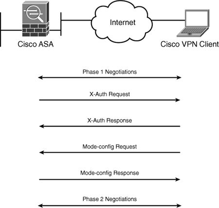
With the Cisco IPSec solution, Cisco ASA allows mobile and home users to establish a VPN tunnel by using Cisco software and Cisco hardware VPN clients. During Phase 1 IKE tunnel negotiations, the Cisco VPN client uses aggressive mode if preshared keys are used and uses main mode when public key infrastructure (PKI) is used. After bringing up the ISAKMP SA for secure communication, Cisco ASA prompts the user to specify the user credentials. In this phase, also known as X-Auth or extended authentication, the security appliance validates the user against the configured authentication database. If the user authentication is successful, Cisco ASA sends a successful authentication message back to the client. After X-Auth, the Cisco VPN client requests configuration parameters such as the IP address and the DNS and WINS server IP addresses, to name a few. During this phase, known as mode-config, the security appliance sends the configured parameters back to the client. The final step for a successful VPN tunnel is the negotiation of Phase 2 parameters, as illustrated in Figure 17-1. After completing the tunnel negotiations, the client can send or receive traffic over the secured connection.
Figure 17-1 Tunnel Negotiations for Cisco VPN Client
Note
It is recommended to use main mode for IKE authentication, which requires RSA signatures because of the known vulnerabilities in aggressive mode.
IPSec Remote-Access Configuration Steps
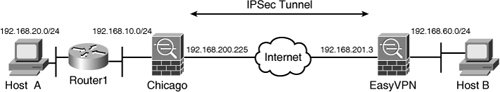
Figure 17-2 illustrates SecureMe’s Chicago hub office, which is to be configured for the Cisco remote-access VPN solution. This topology will be used to show the following configuration steps required to establish a successful VPN tunnel. Many of these steps are identical to the steps discussed in Chapter 16, “Site-to-Site IPSec VPNs.” At the end of each configuration step, we show the equivalent CLI in case you prefer to configure the security appliances through the command line.
Step 3. Set up tunnel and group policies.
Step 5. Configure user authentication.
Step 6. Assign an IP addresss.
Step 8. Configure traffic filtering (Optional).
Step 9. Bypass NAT (Optional).
Step 10. Set up split tunneling (Optional).
Step 11. Define DNS and WINS addresses (Optional).
Figure 17-2 Remote-Access Network Topology for SecureMe

Step 1: Enable ISAKMP
IKE Phase 1 configuration starts by enabling ISAKMP on the interface that terminates the VPN tunnels. Typically, it is enabled on the Internet-facing or the outside interface. If ISAKMP is not enabled on an interface, the security appliance does not listen for the ISAKMP traffic on that interface. If you have a fully configured IPSec tunnel and ISAKMP is not enabled on the outside interface, the security appliance does not respond to a tunnel initialization request.
To enable ISAKMP on an interface, navigate to Configuration > Remote Access VPN > Network (Client) Access > IPSec Connection Profiles and select the Allow Access option next to the interface where you want to terminate the sessions. To terminate the IPSec sessions on the outside interface, select the Allow Access option next to the outside interface. To push this configuration to the security appliance, click the Apply button in ASDM.
Note
When ASDM delivers the commands to enable ISAKMP on an interface, it also configures a number parameters, including
• Two ISAKMP policies (policy numbers 5 and 10). They are discussed in the next section.
• Ten IPSec Policies. They are discussed in the “Define the IPSec Policy” section.
• A dynamic and a static crypto map. The static crypto map is applied to the VPN terminating interface. The crypto maps are discussed in the “Create a Crypto Map” section.
Example 17-1 shows the command line interface (CLI) output if you want to enable ISAKMP on the outside interface.
Example 17-1 Enabling ISAKMP on the Outside Interface
![]()
Tip
IPSec VPN functionality is not available if the Cisco ASA is virtualized, discussed in Chapter 8, “Virtualization,”.
Step 2: Create the ISAKMP Policy
After you enable ISAKMP on the interface, the next step is to create a Phase 1 policy that matches a policy on the VPN client. Phase 1 policy negotiates the encryption and other parameters that are useful in authenticating the remote peer as well as establishing a secure channel over which the VPN client and the security appliance entities can communicate.
To configure a new ISAKMP policy in the security appliance, navigate to Configuration > Remote Access VPN > Network (Client) Access > Advanced > IPSec > IKE Policies and click Add. ASDM launches a new window where you can specify the following attributes:
• Priority—A number between 1 and 65535. By default, ASDM has priority number 5 and 10 preconfigured. If multiple ISAKMP policies are configured, the Cisco ASA checks the ISAKMP policy with the lowest number first. If there is no match, it checks the policy with the next priority number, and so on until all policies have been evaluated. A priority value of 1 is evaluated first, and a priority value of 65535 is evaluated last.
• Encryption—Select the appropriate encryption type from the drop-down list. Cisco ASA employs a dedicated hardware encryption accelerator to process IKE requests. It is recommended that you select AES 256-bit encryption because the performance impact is pretty much the same as using a weaker encryption algorithm such as DES.
• Hash—Select the appropriate hash type, either MD5 or SHA, from the drop-down list. A hashing algorithm provides data integrity by verifying that the packet has not been changed in transit. It is recommended to use SHA because it provides better security than MD5.
• Authentication—Select the appropriate authentication type from the drop-down list. The authentication mechanism establishes the identity of the remote IPSec peer. You can use Preshared Keys, CRACK, or RSA. Chapter 18 discusses RSA signatures in detail.
• D-H Group—Select the appropriate D-H group from the drop-down list. D-H group is used to derive a shared secret to be used by the two VPN devices. The Cisco IPSec clients by default offer D-H group 2 and 5 when proposing IKE policies.
• Lifetime—Specify the lifetime after which a new set of ISAKMP keys are negotiated. You can specify a finite lifetime between 120 and 2,147,483,647 seconds. You can also select unlimited lifetime in case the remote peer does not propose a lifetime. Cisco recommends that you use the default lifetime of 86400 seconds for IKE rekeys.
Figure 17-3 shows that an ISAKMP policy of priority 1 is being added. The encryption method is AES-256, the hashing algorithm is SHA, the authentication mechanism is preshared keys, the D-H group is 2, and the lifetime of 86400 seconds is specified.
Figure 17-3 Defining IKE Policy via ASDM

Note
If the VPN-3DES-AES feature is not enabled, the security appliance allows DES encryption only for the ISAKMP and IPSec policies.
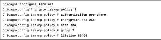
If you prefer the CLI, use the crypto isakmp policy command to define a new policy. Example 17-2 illustrates how to configure an ISAKMP policy for AES-256 encryption, SHA hashing, DH group 2, and preshared keys for authentication, with 86,400 seconds as the lifetime.
Example 17-2 Creating an ISAKMP Policy
Step 3: Set Up Tunnel and Group Policies
Cisco ASA uses an inheritance model when it pushes network and security policies to the end-user sessions. Using this model, you can configure policies at the following three locations:
• Under default group policy
• Under user’s assigned group policy
• Under specific user’s policy
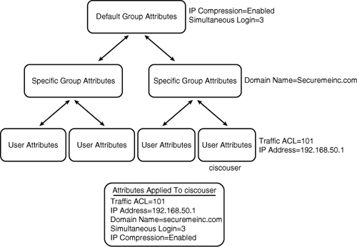
In the inheritance model, a user inherits the attributes and policies from the user policy, which inherits its attributes and policies from the user group-policy, which in turn inherits its attributes and policies from the default group-policy, as illustrated in Figure 17-4. A user, ciscouser, receives a traffic ACL and an IP address from the user policy, the domain name from the user group policy, and IP Compression along with the number of simultaneous logins from the default group policy.
Figure 17-4 ASA Attributes and Policies Inheritance Model
After these policies are defined, they must be bound to a tunnel group where users terminate their sessions. This way, a user who establishes his VPN session to a tunnel group inherits all the policies mapped to that tunnel. The tunnel group defines a VPN connection profile, of which each user is a member.
Configuring Group Policies
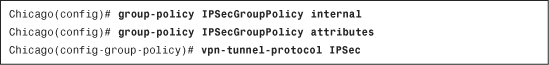
You configure the user group and default group policies by choosing Configuration > Remote Access VPN > Network (Client) Access > Group Policies. Click Add to add a new group policy. As shown in Figure 17-5, a user group policy called IPSecGroupPolicy has been added. This group policy allows only IPSec tunnels to be established and strictly rejects all the other tunneling protocols. If you would rather assign attributes to the default group policy, modify DfltGrpPolicy (System Default). Any attribute that is modified here is propagated to any user group policy that inherits that attribute. A group policy name other than DfltGrpPolicy is treated as a user group policy.
Note
DfltGrpPolicy is a special group name that gets created by default and is used solely for the default group policy.
Figure 17-5 User Group Policy Configuration

The user, group, and default group polices can be applied to clientless, AnyConnect, and IPSec-based remote access VPN tunnels. The IPSec-specific attributes are discussed in detail in the next few sections of this chapter.
Note
You can configure a user policy by choosing Configuration > Remote Access VPN > AAA/Local Users > Local Users.
Example 17-3 illustrates how to define a user group policy called IPSecGroupPolicy. This policy allows only the IPSec tunnels to be terminated on the group.
Example 17-3 Tunnel Group Definition
Configuring a Tunnel Group
A tunnel group, also known as Connection Profile, is used to map the attributes that are assigned to remote access clients. You can configure a new tunnel group by choosing Configuration > Remote Access VPN > Network (Client) Access > IPSec Connection Profiles and clicking Add under Connection Profiles. As shown in Figure 17-6, a tunnel group called SecureMeIPSec with a preshared key of C!$c0K3y (obfuscated) is defined. It is recommended that you configure a long alphanumeric key with special characters. It is hard to decode a complex preshared key even if someone tries to break it by brute force. Under Default Group Policy, select the IPSecGroupPolicy as the group policy” name and also select the Enable IPSec protocol option.
Figure 17-6 Configuration of a Tunnel Group

Note
The concept of tunnel group is taken from the VPN 3000 Series Concentrators.
Example 17-4 illustrates how to configure a remote-access tunnel group of SecureMeIPSec. The preshared key is defined under the ipsec-attributes of the tunnel group, using the pre-shared-key command.
Example 17-4 Tunnel Group Definition

Step 4: Define the IPSec Policy
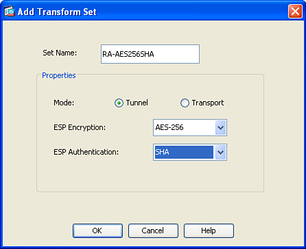
An IPSec transform set specifies what type of encryption and hashing to use for the data packets after a secure connection has been established. This provides data authentication, confidentiality, and integrity. The IPSec transform set is negotiated during Quick Mode. To configure a new transform set through ASDM, navigate to Configuration > Remote Access VPN > Network (Client) Access > Advanced > IPSec > IPSec Transform Sets and click Add. A new window opens, allowing you to configure the following attributes:
• Set Name—Specify the name for this transform set. This name has local significance and is not transmitted during IPSec tunnel negotiations.
• ESP Encryption—Select the appropriate encryption type from the drop-down list. It is recommended that you select AES 256-bit encryption because the performance impact is pretty much the same as using a weaker encryption algorithm such as DES.
• ESP Authentication—Select the appropriate hash type—SHA, MD5, or none—from the drop-down list. A hashing algorithm provides data integrity by verifying that the packet has not been changed in transit. It is recommended to use SHA because it provides better security than MD5.
• Mode—Select the appropriate encapsulation mode from the bullet list. You have the option to use either transport or tunnel mode. Transport is used to encrypt and authenticate the data packets that are originated by the VPN peers. Tunnel mode is used to encrypt and authenticate the IP packets when they are originated by the hosts connected behind the VPN device. In a remote-access connection, tunnel mode is always used.
Note
Cisco ASDM has ten predefined IPSec transform sets. You do not have to define a new transform set if you want to use a predefined transform set.
In Figure 17-7, a new transform set called RA-AES256SHA is being defined. It is set up to use AES-256 encryption and SHA hashing for data packets. The encapsulation mode is defined as tunnel, the default mode.
Figure 17-7 Configuring IPSec Transform Set
Example 17-5 shows how an IPSec transform set can be configured through the CLI.
Example 17-5 Transform-Set Configuration
![]()
Step 5: Configure User Authentication
Cisco ASA supports a number of authentication servers, such as RADIUS, NT domain, Kerberos, SDI, LDAP, digital certificates, smart cards, and local databases. For small organizations, a local database can be set up for user authentication. For medium to large remoteaccess IPSec VPN deployments, it is highly recommended that you use an external authentication server, such as RADIUS or Kerberos, as the user authentication database. If you are deploying remote-access IPSec VPN for a few users, you can use the local database. You define users by choosing Configuration > Remote Access VPN > AAA/Local Users > Local Users > Add. As shown in Example 17-6, two accounts, ciscouser and adminuser, are configured for user authentication. The ciscouser account, with a password of C1$c0123, will be used for IPSec user authentication, whereas adminuser, with a password of @d1m123, will be used to manage the security appliance.
Example 17-6 Local User Accounts
![]()
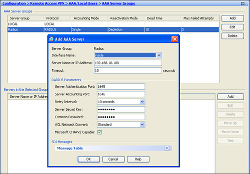
Many enterprises either use a RADIUS server or Kerberos to leverage their existing active directory infrastructure for user authentication. Before configuring an external authentication server on Cisco ASA, you must specify authentication, authorization, and accounting (AAA) server groups by choosing Configuration > Remote Access VPN > AAA/Local Users> AAA Server Groups > Add. Specify a server group name that can be referenced by the other AAA processes. Select an authentication protocol for this server group name. For example, if you plan to use a RADIUS server for authentication, select RADIUS from the drop-down menu. This option ensures that the security appliance requests the appropriate information from the end users and forwards it to the RADIUS server for authentication and verification.
After enabling RADIUS processing, define a list of the RADIUS servers. The Cisco security appliance checks their availability on a round-robin basis. If the first server is not reachable, it tries the second server, and so on. If a server is available, the security appliance keeps using that server until it fails to receive a response. In this case, it checks the availability of the next server. It is highly recommended that you set up more than one RADIUS server in case the first server is not reachable. You can define a RADIUS server entry by navigating to Configuration > Remote Access VPN > AAA/Local Users> AAA Server Groups, selecting the correct AAA server Group, and clicking Add under Servers in the Selected Group. You can specify the IP address of the RADIUS server as well as the interface closest to the server. The security appliance authenticates itself to the RADIUS server by using a shared secret key. The security appliance, for security reasons, never sends this shared secret key over the network.
Figure 17-8 shows the Cisco ASA configured with an AAA server under the server group called Radius. The server is located toward the inside interface at 192.168.1.100 and uses a server secret key of C1$c0123 (obfuscated).
Note
You can optionally modify the authentication and accounting port numbers if your RADIUS server does not use the default ports. The security appliance uses UDP ports 1645 and 1646 as defaults for authentication and accounting, respectively. Most of the RADIUS servers use ports 1812 and 1813 as authentication and accounting ports, respectively.
Figure 17-8 Defining a RADIUS Server for Authentication
After defining the authentication servers, you have to bind them to the IPSec process under a tunnel group. Figure 17-9 illustrates that the newly created Radius AAA server group is mapped to the SecureMeIPSec tunnel group.
Tip
For large VPN deployments (both IPSec and SSL VPNs), you can even control user access and policy mapping from an external authentication server. You should pass the user group policy name as a RADIUS or LDAP attribute to the security appliance. By doing so, you guarantee that a user will always get the same policy, regardless of the tunnel group name to which he connects. If you are using RADIUS as the authentication and authorization server, you can specify the user group policy name as attribute 25 (class attribute). Append the keyword OU= as the value of the class attribute. For example, if you define a user group policy called engineering group, you can enable attribute 25 and specify OU=engineering as its value.
Figure 17-9 Mapping a RADIUS Server to a Tunnel Group

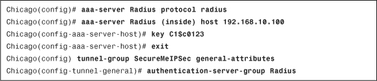
Example 17-7 shows how a radius server can be defined. The radius group name is Radius and it is located toward the inside interface at 192.168.10.100. The shared secret is C1$c0123.
Example 17-7 Defining RADIUS for IPSec Authentication
For configuration of external servers, consult Chapter 6, “Authentication, Authorization, and Accounting (AAA) Services.”
Step 6: Assign an IP Address
During the tunnel negotiations, an IP address is assigned to the VPN adapter of the IPSec VPN Client. The client uses this IP address to access resources on the protected side of the tunnel. Cisco ASA supports three different methods to assign an IP address back to the client:
• DHCP server
• RADIUS server
Many organizations prefer assigning an IP address from the local pool of addresses for flexibility. You can assign the IP address by configuring an address pool and then linking the pool to a group policy. You can either create a new pool of addresses or select a preconfigured address pool. You define a new pool of addresses by choosing Configuration > Remote Access VPN > Network (Client) Access > Address Assignment > Address Pools. Click Add and configure the following attributes, as illustrated in Figure 17-10:
• Name—An alphanumeric name to be assigned to this pool. A pool name of IPPool is assigned.
• Starting IP Address—The first IP address to be assigned to a client. A starting IP address of 192.168.50.1 is assigned.
• Ending IP Address—The last IP address to be assigned to a client. A starting IP address of 192.168.50.254 is assigned.
• Subnet mask—The associated subnet mask for this pool of addresses. A subnet mask of 255.255.255.0 is configured.
Figure 17-10 Defining an Address Pool Through ASDM

By default, all address assignment methods are allowed. If you want to disable a specific address assignment method, you can do so by navigating to Configuration > Remote Access VPN > Network (Client) Access > Address Assignment > Assignment Policy.
Note
If all three methods are configured for address assignment, Cisco ASA prefers RADIUS over DHCP and internal address pools. If Cisco ASA is not able to get an address from the RADIUS server, it contacts the DHCP server for address allocation. If that method fails as well, Cisco ASA checks the local address pool as the last resort.
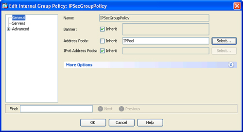
After defining a pool of addresses, map the pool to a user group policy. Choose Configuration > Remote Access VPN > Network (Client) Access > Group Policies > IPSecGroupPolicy > Edit. Deselect the Inherit check box under Address Pools and then click Select to choose a predefined pool of addresses. A new window pops up with all the preconfigured address pools. Select the address pool you want to use and click Assign to map the pool to this policy. In Figure 17-11, the IPPool is assigned to IPSecGroupPolicy. Click OK when finished.
Figure 17-11 Mapping an Address Pool to a Group Policy
Note
A static IP address can be assigned to a user under the user policy. The VPN user receives the same IP address, regardless of the number of times that use connects to the Cisco ASA.
Example 17-8 shows how to assign an address from a pool called IPPool, which is mapped to a group policy called IPSecGroupPolicy.
Example 17-8 Defining Pool of Addresses

Tip
You can also link a pool of addresses to the tunnel group. However, if a pool is mapped to a group policy and a different pool is mapped to a tunnel-group, then the security appliance prefers the pool mapped to the group policy.
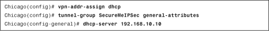
For ease of management, the security appliance can contact a DHCP server when allocating an IP address. After the DHCP server assigns an address, Cisco ASA forwards that IP address to the client. Configure the IP address of the DHCP server by navigating to Configuration > Remote Access VPN > Network (Client) Access > IPSec Connection Profiles > SecureMeIPSec > Edit and specifying an address under the DHCP Servers option. Example 17-9 illustrates how the security appliance in Chicago can be configured to use a DHCP server with an IP address of 192.168.10.10 for address assignment.
Example 17-9 Address Assignment from a DHCP Server
Step 7: Create a Crypto Map
VPN clients often get dynamic IP addresses from their ISPs. In a crypto map, which requires a static IP address for the VPN peer, there is no way to map those dynamic IP addresses. Cisco ASA solves this problem by allowing configuration of a dynamic crypto map. When you enable ISAKMP on an interface, Cisco ASDM preconfigures a dynamic crypto map for you. If you want to change any parameters, you can navigate to Configuration > Remote Access VPN > Network (Client) Access > Advanced > IPSec > Crypto Maps, select the dynamic crypto map—that has a priority of 65535—and click Edit. Example 17-10 demonstrates the configuration of the Cisco ASA to use the defined transform set ESP-AES-256-SHA with the default dynamic crypto map. The dynamic crypto map name is SYSTEM_DEFAULT_CRYPTO_MAP and it is configured with a sequence number of 65535. Assigning a transform set to a dynamic crypto map is a required configuration step.
Example 17-10 Defining Dynamic Crypto Map

You can optionally configure many IPSec attributes in the dynamic crypto map. They include disabling NAT-T, configuring PFS, and reverse-route injection (RRI), and setting security association (SA) lifetimes. Chapter 16 covers these attributes.
When a dynamic map is defined via Cisco ASDM, it also creates a crypto map entry, which eventually gets applied to the interface terminating the IPSec tunnels. Example 17-11 shows the crypto map configuration when a dynamic map called SYSTEM_DEFAULT_CRYPTO_MAP is linked to a static map called outside_map.
Example 17-11 Defining Static Crypto Map

The crypto map can have both static and dynamic crypto map entries, discussed later in the deployment section Load Balancing with Cisco IPSec Clients and Site-to-Site Integration.
The Cisco ASA limits you to apply one crypto map per interface. If there is a need to configure multiple VPN tunnels, use the same crypto map name with a different sequence number. However, the security appliance evaluates a VPN tunnel with the lowest sequence number first.
The next step in setting up a remote-access tunnel is to bind the crypto map to an interface. When ISAKMP is enabled on an interface, Cisco ASDM applies the crypto map on the interface dynamically. If you are configuring the IPSec tunnels via the CLI, use the crypto map command followed by the name of the crypto map and the interface terminating the tunnels. In Example 17-12, the crypto map, outside_map, is applied to the outside interface of the Chicago ASA.
Example 17-12 Applying a Crypto Map to the Outside Interface
![]()
Step 8: Configure Traffic Filtering (Optional)
Like a traditional firewall, the Cisco ASA protects the trusted network from outside traffic, unless the access control lists (ACL) explicitly permit traffic to pass through it. However, by default, the security appliance allows all IPSec traffic to pass through the interface ACLs. For example, even if the outside interface ACL does not permit the decrypted traffic to pass through, the security appliance trusts the remote private network and permits the decrypted packets to pass through.
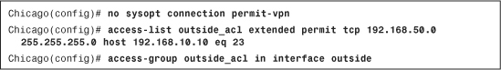
You can change this default behavior, if you want the outside interface ACL to inspect the IPSec protected traffic, by navigating to Configuration > Remote Access VPN > Network (Client) Access > Advanced > IPSec > System Options and deselecting the Enable Inbound IPSec Sessions to Bypass Interface Access-Lists option. If you prefer to use the CLI, issue the no sysopt connection permit-vpn command and define appropriate ACLs to allow VPN traffic to pass through. Example 17-13 shows that only the Telnet traffic from the VPN pool of addresses (192.168.50.0/24) to an inside host located at 192.168.10.10 is allowed to pass through the security appliance.
Example 17-13 Disabling Sysopt and Configuring ACLs
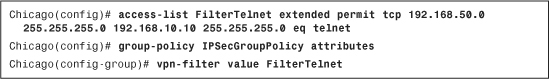
If you do not want to disable the sysopt connection permit-vpn and still want to filter VPN traffic for a specific user or group policy, you can define an access list to allow or deny specific traffic and map that access list to a user or group policy. Using ASDM, choosing Configuration > Remote Access VPN > Network (Client) Access > Group Policies > IPSecGroupPolicy > Edit > General > More Options, deselect the Inherit box for the IPv4 Filter option, and select an ACL from the drop-down menu.
Example 17-14 shows that only the Telnet traffic from the VPN pool of addresses (192.168.50.0/24) to an inside host located at 192.168.10.10 is allowed to pass through the IPSecGroupPolicy.
Example 17-14 Disabling Sysopt and Configuring ACLs
Step 9: Bypass NAT (Optional)
In most cases, you do not want to change the IP addresses for the traffic going over the tunnel. If NAT is configured on the security appliance to change the source or destination IP addresses, you can set up the NAT exemption rules to bypass address translation, as discussed in Chapter 4, “Controlling Network Access,” and in Chapter 16.
Step 10: Set Up Split Tunneling (Optional)
After the tunnel is up, the default behavior of the Cisco IPSec VPN Client is to encrypt traffic to all destination IP addresses. This means that if an IPSec user wants to browse to http://www.cisco.com over the Internet, as illustrated in Figure 17-12, the packets get encrypted and are sent to Cisco ASA. After decrypting them, the security appliance looks at its routing table and forwards the packet to the appropriate next-hop IP address in clear text. These steps are reversed when traffic returns from the web server and is destined to the SSL VPN client.
Figure 17-12 Traffic with No Split Tunneling
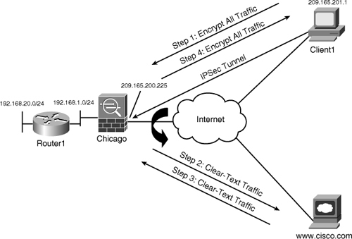
This behavior might not always be desirable for the following two reasons:
• Traffic destined to the nonsecure networks traverses over the Internet twice: once encrypted and once in clear text.
• Cisco ASA handles extra VPN traffic destined to the nonsecure subnet. The security appliance analyzes all traffic leaving and coming from the Internet and that impacts overall device performance.
With split tunneling, the security appliance can notify the IPSec VPN client about the secured subnets. The VPN client, using the secured routes, encrypts only those packets that are destined for the networks behind the security appliance.
Caution
With split tunneling, the remote computer is susceptible to hackers, who can potentially take control over the computer and direct traffic over the tunnel. To mitigate this behavior, a personal firewall is highly recommended on the IPSec VPN clients’ workstations.
The security appliance provides three modes for split tunneling:
• Tunnel all traffic (no split tunneling)
• Tunnel specific networks (split tunneling)
• Tunnel all but specific networks (exclude split tunneling)
In the Tunnel All but Specific Networks options, Cisco ASA tunnels all traffic except for a list of networks that require clear-text access. This feature is useful if users require clear-text access to their local LAN and an encrypted tunnel for all other traffic.
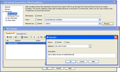
Split tunneling can be configured under a user, user group policy, or default group policy. Choose Configuration > Remote Access VPN > Network (Client) Access > Group Policies > IPSecGroupPolicy > Edit > Advanced > Split Tunneling. Under Policy and Network List, deselect the Inherit check box. Select Tunnel Network List Below from the Policy drop-down menu. Additionally, select a network list from the drop-down menu of Network List. If you would rather define a new network list, click the Manage option. Cisco ASDM launches the ACL Manager and prompts you to define a new list. Under the Standard ACL tab, click Add to add an ACL. In Figure 17-13, a new ACL, called SplitTunnelList has been added. Select the newly defined list, click Add again under the Standard ACL, and add an ACE. An ACE entry for 192.168.10.0/24 has been added with a description of List to Allow Access to Inside Network.
Figure 17-13 Split Tunneling Configuration
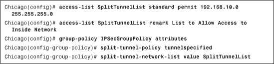
Example 17-14 shows the CLI equivalent of Figure 17-13.
Example 17-14 Split Tunnel Configuration
Step 11: Assign DNS and WINS (Optional)
For the IPSec VPN clients, you can assign DNS and WINS server IP addresses so that they can browse and access internal sites after their tunnel has established. You can configure these attributes by choosing Configuration > Remote Access VPN > Network (Client) Access > Group Policies > IPSecGroupPolicy > Edit > Servers and deselecting the Inherit box for DNS Servers, WINS Servers, and Default Gateway. To add multiple DNS or WINS servers, use a comma (,) to separate the entries. In Figure 17-14, the primary DNS server is defined as 192.168.10.10, and the secondary DNS server is 192.168.10.20. The primary WINS server is 192.168.10.20, and the secondary WINS server is 192.168.10.10. The default domain name to be pushed to the IPSec VPN Client is securemeinc.com.
Figure 17-14 Defining DNS and WINS Servers for IPSec VPN Clients

Example 17-15 shows the CLI equivalent of Figure 17-14.
Example 17-15 Defining DNS and WINS Servers for IPSec VPN Clients

Alternate Configuration Method through ASDM
The simplest and easiest way to define a new IPSec remote access connection is by clicking Wizards in the toolbar and then selecting IPSec VPN Wizard. ASDM launches the VPN Wizard with the option to choose a VPN tunnel type. Follow these steps to successfully define a remote-access IPSec tunnel.
Step 1: Select Tunnel Type
After the IPSec Wizard is launched, the very first thing the ASDM wizard prompts you is to specify the tunnel type. You can either select site-to-site or remote-access tunnels. Select Remote Access as the VPN tunnel type.
The wizard also prompts you to specify the interface that will be terminating the IPSec tunnels. If your VPN terminating interface is the outside interface, select outside from the drop-down menu in the VPN Tunnel Interface field. Make sure the Enable Inbound IPSec Sessions to Bypass Interface Access Lists option is enabled to bypass ACL check for the decrypted traffic. Click Next to move to the Remote Site Peer window.
Step 2: Select Remote Access Client
In the next window, the VPN Wizard prompts you to select the IPSec remote-access client connection. You can select either Cisco VPN Client, Release 3.x or Higher or Microsoft Windows Client Using L2TP over IPSec. For the Cisco VPN client-based connections, select Cisco VPN Client, Release 3.x or Higher and click Next.
Step 3: Select VPN Client Authentication Method
In the next window, the wizard prompts you to select an IKE authentication mechanism such as the preshared keys or preinstalled certificates. Select Pre-shared Keys as the authentication method and specify C!$c0K3y. ASDM also prompts you to specify the tunnel group name. Specify SecureMeIPSec as the group name. Click Next to move to the user authentication window.
Step 4: Specify User Authentication Method
In the next window, the wizard prompts you to select a user authentication mechanism such as the local database or an external server. If you want to use an external server, such as RADIUS, select Authenticate Using an AAA Server Group and select a predefined server group name. If a server is not defined, click New to define a new external authentication server. If you would rather use the local database, select Authenticate Using the Local User Database. After you click Next, ASDM prompts you to add any additional users that you want to declare. If you do not want to add any additional local users, click Next to specify a pool of addresses to be assigned to the VPN clients.
Step 5: Specify an Address Pool
The Cisco ASDM Wizard, in the next window, prompts you to select a predefined pool of addresses under the Pool Name drop-down menu. If a pool of addresses is not currently defined, you can click New and specify a pool name of IPPool, a start address of 192.168.50.1, an end address of 192.168.50.254, and a mask of 255.255.255.0 for the new pool of addresses. Click Next to continue.
Step 6: Specify Attributes Pushed to Clients
After defining the pool of addresses, the Cisco ASDM Wizard prompts you to specify mode-config attributes such as the primary and secondary DNS and WINS server and a default domain name. All these parameters are optional and sent to the VPN client during tunnel negotiations. Specify 192.168.10.10 and 192.168.10.20 as the DNS addresses and 192.168.10.20 and 192.168.10.10 as the WINS addresses. Also specify a domain name of securemeinc.com. Click Next to specify an IKE policy.
Step 7: Select the IKE Policy
Select the appropriate IKE policy for this peer. Use AES-256 for encryption, SHA for authentication, and DH group 5 for key generation to match the configuration with the remote peer. Click Next to move to the IPSec Settings window.
Step 8: Select the IPSec Settings
In the next window, the wizard prompts you to specify some of the optional IPSec parameters such as address translation bypass mechanism, split-tunneling, and perfect forwarding secrecy (PFS). Select the appropriate IKE policy for this peer. If you do not specify any networks in the selected Network/Host list, then the security appliance bypasses addresses translation for the traffic from all internal networks to the pool of addresses. If you specify a specific network, then traffic from that network to the pool of VPN traffic will be bypassed for address translation.
You can also enable split tunneling so that the selected networks and hosts are pushed to the VPN split-tunneling policy. The VPN clients send only encrypted data to the selected networks and hosts, and all other data from the VPN clients is sent out in clear text. To enable split-tunneling, select the Enable Split Tunneling option after selecting the networks/host in the list.
The IPSec Wizard also enables you to enable PFS with the appropriate D-H group type. PFS is discussed in Chapter 16 in more detail.
Step 9: Verify the Configuration
The VPN wizard shows you a summary of all the features and configurations you have set. After you have verified the configuration, click Finish to push the configuration to the security appliance.
Cisco VPN Client Configuration
The Cisco VPN Client, also known as the Cisco Easy VPN Client, initiates the IPSec tunnel to the security appliance. If the configuration and user credentials are valid, the tunnel is established and traffic is processed over it. The Cisco VPN clients come in two different types, which are discussed in the sections that follow:
Software-Based VPN Clients
The software-based VPN client runs on a variety of operating systems, such as Windows, Solaris, Linux, and Mac OS/X. It can be downloaded from Cisco.com free of charge as long as the Cisco ASA is under a valid service contract.
Before you configure the Cisco VPN client, it needs to be installed on the host machine. Please refer to http://www.cisco.com/go/vpnclient for the installation instructions. Cisco ASA supports version 3.x or higher VPN clients.
Note
The installation of Cisco VPN Client requires administrative privileges on the workstation.
In Windows-based operating systems, you launch the VPN client by running the VPN client executable found under Start > Program > Cisco Systems VPN Client after it is installed. The operating system runs the executable and displays the VPN Client utility.
The configuration of a Windows-based VPN client requires five parameters:
• Name of the connection entry
• Public IP address of the Cisco ASA
• Group name to which the VPN client will be connecting
• Group preshared key
• Tunnel encapsulation
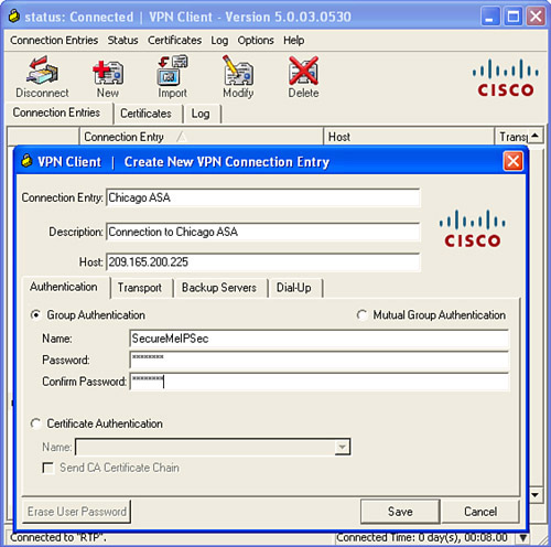
You can configure these parameters on the Cisco VPN client by clicking the New icon. The Cisco VPN client shows a different window in which you can enter the necessary information. In Figure 17-15, the user has specified the Connection Entry as Chicago ASA. You can name this entry any way you like because it is locally significant and is not forwarded to the security appliance. You can optionally enter the description for this connection entry. In this example, the connection description is Connection to Chicago ASA. The VPN client requires you to input the IP address or the hostname of the security appliance. Because the public IP address of the security appliance in Chicago is 209.165.200.225, the VPN client is set up to use this address. The group name that the VPN client is configured to use is SecureMeIPSec, and the group password is C!$c0K3y, displayed as asterisks. The group password on the client is the preshared key configured on the security appliance.
Figure 17-15 VPN Client Configuration
You can specify what type of data encapsulation the Cisco VPN client should be using. This is set up under the Transport tab. If IPSec over UDP or NAT-T is the encapsulation mode, then check the Enable Transparent Tunneling box with IPSec over UDP (NAT/PAT) as the selected option. If IPSec over TCP is the required encapsulation, then select IPSec over TCP and specify the appropriate port number.
Note
The security appliance must to be set up for transparent tunneling as well. Consult the upcoming section “Transparent Tunneling” for a detailed explanation and configuration.
Note
If the Enable Transparent Tunneling box in the Transport tab is disabled, the VPN client uses only the native IPSec encapsulation mode, using ESP.
After configuring the VPN client, the user can click the Connect icon to establish the connection to the security appliance.
Hardware-Based VPN Clients
The Cisco hardware-based VPN clients can also provide the remote-access IPSec functionality by using the dedicated Cisco hardware devices. Easy VPN is supported on the following platforms:
• Cisco IOS router
• Cisco PIX Firewall
• Cisco ASA 5505
• Cisco VPN 3002 hardware client
A Cisco 5505 security appliance can act as a VPN client and initiate a VPN tunnel on behalf of the hosts residing on the private subnet, as shown in Figure 17-16. When the 5005 ASA receives interesting traffic destined to pass over the VPN tunnel, it initiates an IPSec tunnel to the IP address of the headend security appliance.
Figure 17-16 Cisco ASA-Based Easy VPN Client Connecting to Headend Cisco ASA
Two connection modes are supported by the hardware-based Easy VPN devices:
• Client mode—Also called the Port Address Translation (PAT) mode. It isolates all hosts on the private side of the hardware VPN client from those on the corporate network. The hardware-based Easy VPN client translates all traffic initiated by the hosts on the private side to a single-source IP address before sending it over the tunnel. This source IP address is assigned to the client by the security appliance during the mode-config exchange. The client translates the original source IP address by assigning a random source port. The client keeps and maintains a port translation table to identify where to send responses on the private network. Using the client mode, the hosts on the private network can initiate traffic destined to the corporate network. However, the hosts on the corporate network cannot initiate traffic back to the private network of the Easy VPN client.
• Network Extension Mode (NEM)—Acts similarly to a site-to-site tunnel in that hosts behind the corporate network can initiate traffic destined to the network behind the Easy VPN client, and vice versa. Thus, hosts on either side know each other by their actual addresses. The major difference between the site-to-site and NEM VPN tunnels is that when you use NEM VPN tunnels, the IPSec connection has to be initiated by the Easy VPN client. Using NEM, there is no need for the security appliance to assign an IP address to the client. Therefore, the client does not participate in PAT for traffic destined over the VPN tunnel.
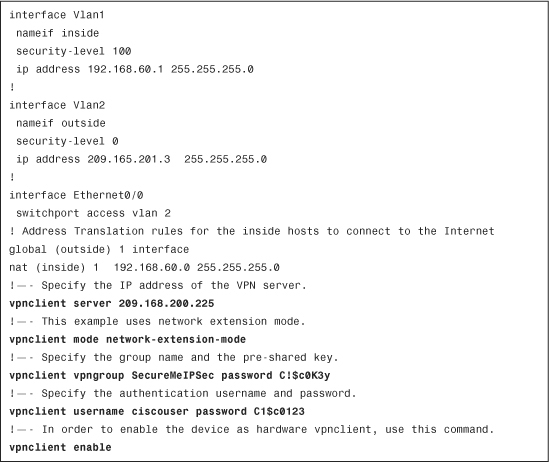
The Easy VPN configuration on the Cisco ASA 5505 requires the use of vpnclient commands. In Example 17-16, EasyVPN is configured on a 5505 to connect to the headend ASA’s public IP address of 209.165.200.225. The group name that the EasyVPN client is using is SecureMeIPSec, with the group password of C!$c0K3y. The administrator has set up network-extension-mode for this connection. For X-Auth, a username of ciscouser with a password of C1$c0123 is being configured.
Example 17-16 Cisco 5505 Easy VPN Client Configuration
Note
For Cisco PIX, IOS and VPN 3002 Hardware Client installation and configuration documents, refer to the following links.
PIX Easy VPN Client:
http://www.cisco.com/en/US/docs/security/pix/pix63/configuration/guide/pixclnt.html
http://www.cisco.com/go/easyvpn
VPN 3002 Hardware Client:
http://www.cisco.com/univercd/cc/td/doc/product/vpn/vpn3002/4-1/referenc/tunnel.htm
Advanced Cisco IPSec VPN Features
Cisco ASA provides many advanced features to suit your remote-access VPN implementations, including the following:
• Client auto-update
• Easy VPN features
Tunnel Default Gateway
A Layer 3 device typically has a default gateway that it uses to route packets when the destination address is not found in its routing table. Tunnel default gateway is used to route packets if they reach the security appliance over an IPSec tunnel and if their destination IP address is not found in the routing table. The tunneled traffic can be either remote access or site-to-site VPN traffic. The tunnel default gateway next-hop address is generally the IP address of the inside router, or any Layer 3 device.
The tunnel default gateway feature is important if you do not want to define routes for your internal networks on the Cisco ASA, and instead you want all tunneled traffic to be sent to the internal router for routing.
To set up a tunnel default gateway, navigate to Configuration > Device Setup > Routing > Static Routes > Add. A new window appears where you can add a default route with the gateway IP being the next-hop IP address of the inside router (Router1). Make sure that you select the Tunneled radio button, as shown in Figure 17-17.
Figure 17-17 Defining a Tunnel Default Gateway

If you prefer to use the CLI, make sure that you add the keyword tunneled to the statically configured default route. Example 17-17 shows the configuration of the appliance with the tunnel default gateway specified as 192.168.10.2, located on the inside interface.
Example 17-17 Tunnel Default Gateway Configuration
![]()
Transparent Tunneling
In many network topologies, the VPN clients reside behind a NAT/PAT device that inspects the Layer 4 port information for address translation. Because IPSec uses ESP (IP protocol 50), which does not have Layer 4 information, the PAT device is usually incapable of translating the encrypted packets going over the VPN tunnel. To remedy this problem, Cisco ASA offers three solutions:
NAT Traversal
NAT-T, RFC 3947, is a feature that encapsulates the ESP packets into UDP port 4500 packets. NAT-T is dynamically negotiated if the following two conditions are met:
• Both VPN devices are NAT-T-capable
• A NAT or PAT device exists between VPN peers
If both conditions are true, the VPN client tries to connect to the security appliance, using UDP port 500 for IKE negotiations. As soon as the VPN peers discover that they are NAT-T-capable and a NAT/PAT device resides between them, they switch over to UDP port 4500 for the rest of tunnel negotiations and data encapsulation.
NAT-T is globally enabled on the security appliance by default, with a default keepalive timeout of 20 seconds. In many cases, the NAT/PAT devices time out the UDP port 4500 entries if no active traffic is passing through them. NAT-T keepalives are used so that the security appliance can send periodic keepalive messages to prevent the entries from timing out. You can specify a NAT-T keepalive range between 10 and 3600 seconds.
If NAT-T is not enabled for some reason, you can enable it by navigating to Configuration > Remote Access VPN > Network (Access) Client > Advanced > IPSec > IKE Parameters and then checking off the Enable IPSec over NAT-T option. Example 17-18 illustrates how NAT-T is globally enabled in the CLI, with keepalives sent to every 30 seconds.
Example 17-18 Enabling NAT-T Globally
![]()
Note
NAT-T is supported on Cisco VPN clients running version 3.6 or higher.
IPSec over UDP
IPSec over UDP, similar to NAT-T, is used to encapsulate the ESP packets using a UDP wrapper. This is useful in scenarios where the VPN clients do not support NAT-T and are behind a firewall that does not allow ESP packets to pass through. In IPSec over UDP, the IKE negotiations still use UDP port 500. During the negotiations, Cisco ASA informs the VPN client to use IPSec over UDP for data transport. Additionally, Cisco ASA updates the VPN client about the UDP port it should use.
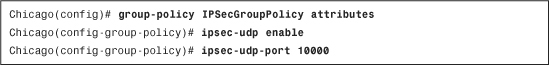
You can enable IPSec over UDP in a user group policy by navigating to Configuration > Remote Access VPN > Network (Client) Access > Group Policies > IPSecGroupPolicy > Edit > Advanced > IPSec Client and deselecting the inherit option for the IPSec Over UDP and IPSec Over UDP Port parameters. Select Enable for IPSec over UDP and port 10000 for IPSec Over UDP Port.
Example 17-19 shows how Cisco ASA can be set up in the CLI to use IPSec over UDP for the remote-access group IPSecGroupPolicy. Cisco ASA pushes UDP port 10000 as the data encapsulation port to the VPN client.
Example 17-19 IPSec over UDP Configuration
IPSec over TCP
IPSec over TCP is an important feature used in scenarios where
• UDP port 500 is blocked, resulting in incomplete IKE negotiations.
• ESP (IP protocol 50) is not allowed to pass, and as a result encrypted traffic does not traverse.
• The network administrator prefers to use a connection-oriented protocol.
With IPSec over TCP, the security appliance negotiates the VPN tunnel, using TCP as the protocol over a preconfigured port. When the tunnel is up, both VPN devices (Cisco ASA and the VPN client) pass traffic through the same connection. You can enable it by navigating to Configuration > Remote Access VPN > Network (Access) Client > Advanced > IPSec > IKE Parameters, then selecting the Enable IPSec over TCP option, and then specifying a port number. Example 17-20 illustrates how to configure IPSec over TCP on Cisco ASA. The administrator of the security device prefers to use TCP port 10000 for tunnel setup and data transport. Cisco ASA allows up to ten TCP ports to be used for this feature.
Example 17-20 IPSec over TCP Configuration
![]()
To verify whether the VPN clients are using IPSec over TCP, you can use the show crypto ipsec sa | include settings command, as demonstrated in Example 17-21. The In Use Settings option indicates that the particular VPN connection is a remote-access tunnel using TCP encapsulation.
Example 17-21 Verifying VPN Client Use of IPSec over TCP

IPSec Hairpinning
Cisco ASA, by default, does not allow a packet to leave the same interface on which it was originally received. Cisco ASA supports receiving the IPSec traffic from one VPN tunnel and then redirecting it into a different VPN tunnel, if both tunnels terminate on the same interface. This feature is known as IPSec hairpinning. Using this feature, you can implement a true hub-and-spoke scenario, as shown in Figure 17-18.
Figure 17-18 IPSec Hairpinning
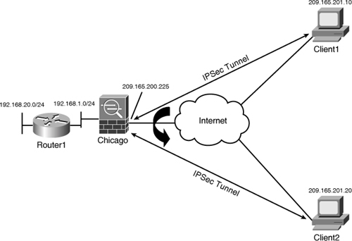
If Client1 needs to send traffic to Client2, it sends all traffic to the hub Cisco ASA. The hub Cisco ASA, after checking the routing table for the destination address, sends traffic to Client2 over the other VPN tunnel, and vice versa. However, this feature requires both remote VPN devices to be a part of the same crypto map and the crypto map must be applied to the same interface.
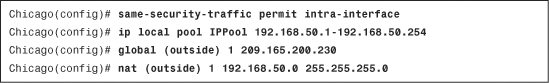
You can enable IPSec hairpinning by navigating to Configuration > Device Setup > Interfaces and selecting the Enable Traffic Between Two or More Hosts Connected to the Same Interface option. Using the CLI, you can use the global same-security-traffic permit intra-interface command to permit VPN traffic to leave the same physical interface when traffic needs to go over the other VPN tunnel.
Cisco ASA also supports receiving traffic from an IPSec client and then redirecting it to the Internet in clear text. This feature, also known as Client U-turn, is useful if you
• Are not using split-tunneling and all traffic is sent to the security appliance.
• Want to provide Internet access to your IPSec clients.
• Do not want return traffic from the Internet that is destined to the VPN clients to enter the inside network of your organization.
Cisco ASA applies firewall rules (ACL checking, packet inspection, NAT, IDS, URL filtering) before sending traffic out to the same interface for both IPSec hairpinning and Client U-turn. As shown in Example 17-22, if the pool of addresses is 192.168.50.0/24, then you must configure the NAT and global commands to allow the VPN client traffic to access the Internet. Additionally, both global and nat commands must be attached to the same interface.
Example 17-22 Allowing VPN Clients for Internet Access
VPN Load Balancing
VPN load balancing is a way to distribute remote-access IPSec and SSL VPN connections across multiple security appliances. When two or more Cisco ASA devices are deployed in load balancing, they form a virtual cluster, with one of the security appliances acting as the cluster master. All Cisco ASA devices in the cluster are configured with a virtual IP address, and the cluster master takes ownership of that IP address, as illustrated in Figure 17-19.
Figure 17-19 VPN Load-Balancing

The VPN clients use this IP address to initiate the tunnel request. The master appliance, after receiving the request, looks at the load-balance database and determines which security appliance has the least load. The master appliance sends a redirect message back to the client with the IP address of the security appliance to which the client should connect. After receiving the IP address of the Cisco ASA, the client initiates a new request to the Cisco ASA and goes through the IKE negotiations.
Note
The Cisco ASA load-balancing feature is fully compatible with the load-balancing feature on the VPN3000 concentrators. This is useful if you are migrating from an existing VPN 3000 deployment to a Cisco ASA environment and want to use both devices for a period of time.
The load-balancing feature is supported on the following remote access client types:
• Cisco AnyConnect VPN Client (Release 2.0 or higher)
• Cisco IPSec VPN Client (Release 3.0 and later)
• Cisco ASA 5505 Security Appliance as an Easy VPN client
• Cisco VPN 3002 Hardware Client (Release 3.5 or later)
• Cisco PIX 501/506E as an Easy VPN client
• IOS Easy VPN Client devices, such as 831/871 supporting IKE-redirect
• Clientless SSL VPN
Note
Load balancing is not supported on L2TP over IPSec tunnels and IPSec site-to-site tunnels.
To set up VPN load balancing, navigate to Configuration > Remote Access VPN > Load Balancing and configure the following attributes:
• Participate in Load Balancing Cluster—Enable this box if you want this security appliance to participate in load balancing the remote-access sessions.
• Cluster IP Address—The cluster IP address is the virtual IP address of the load-balancing cluster that the remote-access clients use to establish their initial connections.
• UDP Port—Specify a port that is used by the security appliance to send and receive the load-balancing information. By default, it uses UDP port 9023.
• Enable IPSec Encryption—Enable this box if you want the Cisco ASAs to optionally secure their communication when they exchange load-balancing information.
• IPSec Shared Secret—Specify a shared secret to be used by the load-balancing process to encrypt communication. If there is a mismatch in the key, the security appliance fails to join the cluster.
• Public Interface—Specify the interface that terminates the IPSec tunnels. By default, it is the outside interface.
• Private Interface—Specify the interface that connects to the internal network. By default, it is the inside interface. You must enable ISAKMP processing on the inside interface if you choose to encrypt load-balancing information.
• NAT Assigned IP address—If the Cisco ASA devices sit behind a NAT device, then you can configure the security appliance’s translated IP address as the NAT assigned IP address.
• Priority—You can set the appropriate priority to indicate the likelihood of a Cisco ASA device becoming the cluster master, either during bootup or when the existing cluster master fails to respond. The default priority of Cisco ASA devices is determined based on the model number. Table 17-2 lists all the default priorities of the Cisco ASA devices.
Table 17-2 Appliances and the Default Load-Balancing Priorities
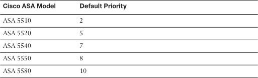
If two Cisco ASA devices with the same priority are powered up simultaneously, then the security appliance with the lowest IP address becomes the cluster master. Otherwise, the security appliance with the highest priority assumes the role of master cluster.
If the cluster master fails to respond during operation, the secondary appliance with the highest priority becomes the new cluster master. You can specify a priority between 1 and 10. When the original master appliance comes online, it does not preempt to regain control
Note
Cisco ASA 5510 supports the VPN load-balancing feature if you are running version 8.0(2) or higher with the Security Plus license.
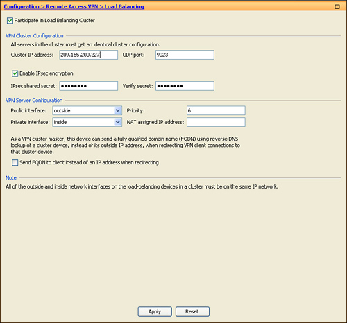
In Figure 17-20 a security appliance is configured to participate in VPN load balancing. The cluster IP address is 209.165.200.227, whereas the IPSec shared secret is C1$c0123. The device priority is 6.
Figure 17-20 Configuring VPN Load Balancing
If you prefer to configure VPN load balancing via the CLI, Example 17-23 shows the relevant configuration.
Example 17-23 VPN Load-Balancing Configuration with Encryption

Note
VPN load balancing requires you to enable ISAKMP on all the interfaces participating in load balancing. If you enable load balancing but ISAKMP is not enabled on an interface, you receive the following error message.
Chicago(config-load-balancing)# participate
ERROR: Need to enable isakmp on interface inside to use encryption.
Client Firewalling
The Cisco VPN client has an integrated personal firewall that protects a machine from the Internet by inspecting packets both inbound and outbound. When you have the firewall option enabled on the VPN client, the client provides extra security if the VPN tunnel-group to which the user is connecting has split tunneling enabled. In this way, the VPN client firewall denies packets received from the unprotected networks, resulting in more secure corporate networks. Cisco ASA supports two different scenarios for client firewalling, discussed in the sections that follow.
Note
Only Windows VPN clients support the client firewalling feature.
Personal Firewall Check
The Cisco VPN client can check to see whether the firewall service on the machine is running by sending periodic keepalives, also known as Are you there (AYT) messages, to the specified VPN client firewall. If the firewall service on the client machine is not running, the VPN client fails to establish the secured connection. Additionally, if the VPN tunnel is up and the user manually turns off the firewall service, the keepalives time out and the Cisco VPN client drops the connection.
You can configure the client firewall option under Configuration > Remote Access VPN > Network (Client) Access > Group Policies > IPSecGroupPolicy > Edit > Advanced > IPSec Client > Client Firewall. Uncheck the Inherit from default group policy box and select a firewall type. An administrator can set up Cisco ASA for three firewall check types:
• No Firewall—The personal firewall check is disabled. This mode is useful if non-Windows clients are connecting to a group.
• Firewall Optional—Cisco ASA checks to see whether the firewall services on the VPN client are running. If they are disabled, Cisco ASA still allows the VPN connection to come up. This mode is useful if Windows and non-Windows clients connect to a group.
• Firewall Required—If the firewall service is not running, Cisco ASA does not allow the VPN tunnel to be established. This mode is recommended if only Windows clients connect to a group.
For optional (opt) and required (req) modes, Cisco ASA provides a list of currently supported personal firewalls, including the built-in Cisco Integrated Client Firewall. As shown in Figure 17-21, Cisco Security Agent (CSA) is selected as a required firewall before the VPN sessions are allowed to connect. If the VPN clients don’t have this firewall running, Cisco ASA stops the tunnels from getting established.
Note
You can define a customized firewall, if you know the vendor ID and product ID, by using the Custom Firewall option.
Figure 17-21 Configuring Client Firewall Check

Central Protection Policy
When split tunneling is employed, Cisco ASA can additionally send security policies in the form of ACLs to the client machine and restrict its clear-text traffic capabilities. This deployment scenario, known as Centralized Protection Policy (CPP) or policy pushed, uses ACLs that can be pushed to the client firewall. This feature is extremely useful if you want your remote users to browse a limited set of IP addresses when they are sending traffic in clear-text and want to filter out all other traffic.
Note
CPP is supported in only those Windows VPN clients that have the integrated stateful firewall functionality. Microsoft Windows 2003 and Windows Vista do not support this feature.
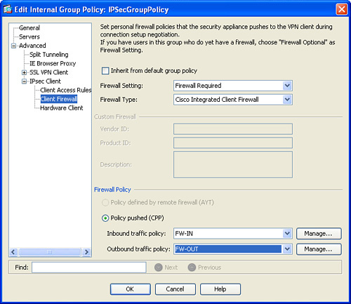
To define a CPP, navigate to Configuration > Remote Access VPN > Network (Client) Access > Group Policies > IPSecGroupPolicy > Edit > Advanced > IPSec Client > Client Firewall. Uncheck Inherit from default group policy and select Firewall Required as the Firewall Setting. Also select Cisco Integrated Client Firewall (CIC) as the Firewall Type. Under Firewall Policy, make sure that Policy Pushed (CPP) is selected. ASDM enables you to select an inbound and an outbound policy to be applied to the user connections. If you do not have an ACL defined, click the Manage button and a new window pops up where you can specify the ACLs to be pushed to the user connections.
As shown in Figure 17-22, ASDM requires that the VPN client use the Cisco Integrated Client Firewall (CIC). Cisco ASA also restricts the client machine to send and receive traffic based on the configured inbound ACL, named FW-IN, and the outbound ACL, named FW-OUT. These ACLs allow IP traffic only from 192.168.100.0/24 (Target network) to 192.168.50.0/24 (VPN Pool of addresses) and vice versa.
Figure 17-22 Configuring Centralized Protection Policy
Note
The CIC ACLs are defined from the VPN client’s perspective. That means the outbound ACL should have the pool of addresses as the source and the target network as the destination. Similarly, the inbound ACL should have the target network as the source and the pool of addresses as the destination.
If you are defining ACLs at the protocol level, make sure that you allow DNS queries and the responses in the policies. For example, if the DNS server resides at 192.168.101.1, then allow port 53 for the DNS server’s IP address in your ACLs.
You can define an identical policy as Figure 17-22 via the CLI, as shown in Example 17-24.
Example 17-24 Configuration of Central Protection Policy

Hardware-Based Easy VPN Client Features
Cisco ASA can provide further security for the Hardware-Based Easy VPN client if you enable specific features under Configuration > Remote Access VPN > Network (Client) Access > Group Policies > IPSecGroupPolicy > Edit > Advanced > IPSec Client > Hardware Client and uncheck the Inherit box. Figure 17-23 displays these features and shows ASDM configuration when all these features are turned on.
Figure 17-23 Configuring Hardware-Based Easy VPN Features
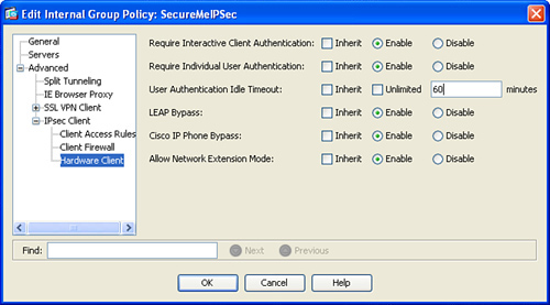
Interactive Client Authentication
Cisco ASA can use the interactive hardware client authentication feature, also known as secure unit authentication, which ensures that the Hardware-Based Easy VPN client provides user credentials every time the tunnel is negotiated. That way, the security appliance does not allow user passwords to be saved on the Hardware-Based Easy VPN client, which provides additional security. If the user password is saved on the Hardware-Based Easy VPN client, Cisco ASA pushes down a policy during mode-config to delete the saved password from the Hardware-Based Easy VPN client configuration. Select the Require Interactive Client Authentication option to enable this feature. Example 17-25 shows configuration to set up Cisco ASA for interactive hardware client authentication for the IPSecGroupPolicy group.
Example 17-25 Configuration of Interactive Client Authentication

Individual User Authentication
Using the Individual User Authentication feature, Cisco ASA secures the VPN tunnel by making sure that users behind the Hardware-Based Easy VPN Client are authenticated before they can access corporate resources. To be able to pass traffic over the tunnel, a user behind the Hardware-Based Easy VPN client must launch a web browser and present valid user credentials. The Hardware-Based Easy VPN client forwards the user information to the Cisco ASA, which in turn uses the configured authentication method to validate the user information.
Tip
The user does not have to manually point the web browser to the IP address of the Hardware-Based Easy VPN client. Instead, users can try to browse to any server behind the security appliance, and the Hardware-Based Easy VPN client redirect them for user credentials.
Select the Require Individual User Authentication to enable this feature. Example 17-26 shows the Cisco ASA configuration for Individual User Authentication for the IPSecGroupPolicy group.
Example 17-26 Configuration of Individual User Authentication
![]()
You can also specify the idle-time period if there is no activity over a user’s connection. When the idle-time period expires, Cisco ASA terminates that particular connection. Specify the timeout in minutes or as unlimited under the User Authentication Idle Timeout option. In Example 17-27, group IPSecGroupPolicy is configured to time out inactive users after 60 minutes.
Example 17-27 Configuration of Individual User Idle Timeout
![]()
LEAP Bypass
LEAP bypass is a feature in the security appliance that allows Lightweight Extensible Authentication Protocol (LEAP) packets to go over the VPN tunnel when individual hardware client authentication is configured. You can enable LEAP bypass by selecting the LEAP Bypass option. Example 17-29 shows the Cisco ASA configuration for LEAP bypass for the IPSecGroupPolicy group.
Example 17-29 Configuration of Cisco Aironet LEAP Bypass
![]()
Note
This feature works only with Cisco Aironet access points using LEAP for authentication. It does not work if interactive hardware client authentication is enabled.
Cisco IP Phone Bypass
When individual hardware client authentication is enabled, Cisco ASA tries to authenticate Cisco IP Phones if they send traffic to go over the tunnel. You can set up the security appliance to bypass authentication for Cisco IP Phones by enabling the Cisco IP Phone Bypass option. In Example 17-28, this feature is enabled for IPSecGroupPolicy group policy.
Example 17-28 Configuration of Cisco IP Phone Bypass
![]()
Note
For this feature to work, make sure that the Hardware-Based Easy VPN client is using network extension mode.
Hardware Client Network Extension Mode
You have the option to configure a group policy to disable network extension mode (NEM) on Cisco ASA. When you use this option, the Hardware-Based Easy VPN clients are restricted to using client/PAT mode for VPN tunnels. If they try to use NEM, Cisco ASA blocks the tunnel from being established. You can enable NEM by selecting Allow Network Extension Mode. Example 17-30 shows the Cisco ASA configuration to allow NEM for the IPSecGroupPolicy group.
Example 17-30 Configuration to Allow NEM
![]()
L2TP Over IPSec Remote Access VPN Solution
Organizations that prefer to use a built-in remote access client in the Windows-based operating systems can use L2TP. However, L2TP fails to provide strong data confidentiality. Therefore, most of the L2TP implementations use IPSec to provide data security. This methodology is commonly referred to as L2TP over IPSec and is documented in RFC 3193.
In an L2TP over IPSec implementation, the client workstation and the security appliance go through seven steps, as depicted in Figure 17-24.
Figure 17-24 L2TP over IPSec Negotiations

Step 1. The user establishes a PPP session to the service provider access router and receives a dynamic public IP address. This step is optional if the workstation already has an IP address and can send traffic to the Internet.
Step 2. The user launches the L2TP client that is configured to use IPSec for data security.
Step 3. The client workstation initiates a session and negotiates a secure channel for exchanging keys (Phase 1 negotiations of IPSec).
Step 4. After successfully establishing Phase 1, the client establishes two secure channels for data encryption and authentication (Phase 2 negotiations of IPSec). The data channels are set up to encrypt L2TP traffic that is destined to UDP port 1701.
Step 5. After IPSec is established, the client initiates an L2TP session within IPSec.
Step 6. The user-specified authentication credentials are used to validate the L2TP session. Any PPP or L2TP attributes are negotiated after the user has been successfully authenticated.
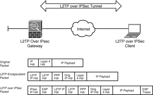
Step 7. After the L2TP session is established, the user workstation sends data traffic that is encapsulated within L2TP. The L2TP packets are encrypted by IPSec and then sent out to the other end of the tunnel over the Internet.
Note
If you have a firewall between the L2TP over an IPSec client and the home gateway, you need to allow IP protocol 50 (ESP) and UDP port 500 to pass through. L2TP packets (UDP port 1701) are encapsulated within ESP. Some L2TP over IPSec vendors allow NAT transparency (NAT-T) by encapsulating traffic into UDP port 4500.
Figure 17-25 shows an L2TP over IPSec packet format after all the headers and encapsulations have been added to the original packet.
Figure 17-25 L2TP over IPSec Packet Format
Note
You can have multiple L2TP over IPSec clients behind a PAT device terminate their session on the security appliance using NAT-T. For more information about NAT-T on Windows platforms, refer to the Microsoft knowledge base article number 926179:
L2TP over IPSec Remote-Access Configuration Steps
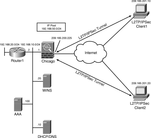
Figure 17-26 illustrates SecureMe’s Chicago hub office to be configured for the L2TP over IPSec solution. This topology will be used to show the following configuration steps required to establish a successful tunnel. The best way to successfully establish an IPSec remote-access tunnel is through the use of the ASDM wizard. Many of these steps are identical to the steps discussed earlier in the chapter under the Cisco IPSec VPN client configuration section.
Figure 17-26 L2TP over IPSec Network Topology
Launch the IPSec VPN wizard by clicking Wizards in the toolbar and then selecting IPSec VPN Wizard. ASDM launches the VPN Wizard with the option to choose a VPN tunnel type. Follow the steps in the following sections to successfully define a L2TP over IPSec remote access tunnel.
Step 1: Select Tunnel Type
After the IPSec wizard is launched, the very first thing the ASDM wizard prompts you to do is to specify the tunnel type. You can either select site-2-site or remote-access tunnels. Select Remote Access as the VPN tunnel type.
The wizard also prompts you to specify the interface that will be terminating the IPSec tunnels. If your VPN terminating interface is the outside interface, select outside from the drop-down menu in the VPN Tunnel Interface field. Make sure that Enable Inbound IPSec Sessions to Bypass Interface Access option is enabled to bypass ACL check for the decrypted traffic. Click Next to move to the Remote Site Peer window.
Step 2: Select Remote Access Client
In the next window, the VPN Wizard prompts you to select the IPSec remote-access client connection. You can either select Cisco VPN Client, Release 3.x or Higher or select Microsoft Windows Client Using L2TP over IPSec. For the L2TP over IPSec connections, select Microsoft Windows Client Using L2TP over IPSec. Specify a PPP authentication protocol. Cisco ASA supports:
• PAP—It is the most unsecure form of authentication because it sends username and password in cleartext.
• CHAP—It is considered more secure than PAP because the username is sent in cleartext but the password is sent as a response to a challenge by the server. The data, however, is sent in cleartext.
• MS-CHAP—It is an enhanced version of CHAP in which the client sends a response in MD4 hash to a challenge by the server.
• MS-CHAP2—It offers additional security enhancements over MS-CHAP version 1, such as mutual authentication between peers.
• EAP-Proxy—It allows the security appliance to proxy the PPP authentication process to an external RADIUS authentication server.
You can choose one or more authentication protocols. An authentication protocol is negotiated based on what is offered by the L2TP over IPSec client. Select MS-CHAP and MS-CHAP2 as the authentication protocols. Click Next.
Step 3: Select VPN Client Authentication Method
In the next window, the wizard prompts you to select an IKE authentication mechanism such as the preshared keys or pre-installed certificates. Select Pre-shared Keys as the authentication method and specify C!$c0K3y. Click Next to move to the user authentication window.
Step 4: Specify User Authentication Method
In the next window, the wizard prompts you to select a user authentication mechanism such as the local database or an external server. If you want to use an external server, such as RADIUS, select Authenticate Using an AAA Server Group and select a predefined server group name. If a server is not defined, you can click New and define a new external authentication server. If you would rather use the local database, select Authenticate Using the Local User Database. After you click Next, ASDM prompts you to add any additional users that you want to declare. If you do not want to add any additional local users, click Next.
Step 5: Specify an Address Pool
In the next window, the Cisco ASDM Wizard prompts you to select a predefined pool of addresses under the Pool Name drop-down menu. If a pool of addresses is not currently defined, you can click New and specify a start address of 192.168.50.1 and an end address of 192.168.50.254 for the new pool of addresses. Click Next.
Step 6: Specify Attributes Pushed to Clients
After defining the pool of addresses, the Cisco ASDM Wizard prompts you to specify mode-config attributes such as the primary and secondary DNS and WINS server and a default domain name. All these parameters are optional and sent to the VPN client during L2TP tunnel negotiations. Specify 192.168.10.10 as the DNS address and 192.168.10.20 as the WINS address. Define securemeinc.com as the default domain name. Click Next to specify an IKE policy.
Step 7: Select the IKE Policy
Select the appropriate IKE policy for this peer. Use AES-256 for encryption, SHA for authentication, and DH group 5 for key generation to match the configuration with the remote peer. Click Next to move to the IPSec Settings window.
Step 8: Select the IPSec Settings
In the next window, the wizard prompts you to specify some of the optional IPSec parameters such as address translation bypass mechanism, split-tunneling, and perfect forwarding secrecy (PFS). Select the appropriate IKE policy for this peer. If you do not specify any networks in the selected Network/Host list, then the security appliance bypasses addresses translation for the traffic from all internal networks to the pool of addresses. If you specify a specific network, then traffic from that network to the pool of VPN traffic will be bypassed for address translation.
Step 9: Verify the Configuration
The VPN Wizard shows you a summary of all the features and configuration you have done. After you have verified the configuration, click Finish to push the configuration to the security appliance.
Windows L2TP over IPSec Client Configuration
On Windows devices such as Windows XP, you can configure the basic L2TP over IPSec parameters by following these steps:
Step 1. Create a new connection by navigating to Start > Settings > Control Panel > Network Connections. Under Network Tasks left panel, click Create a New Connection. Windows launches the New Connection Wizard. Click Next to define a new connection entry.
Step 2. Select Connect to the Network at My Workplace and click Next.
Step 3. Under Network Connection, select Virtual Private Network Connection and click Next.
Step 4. Specify a name for this connection, such as L2TPIPSecCorp, and click Next.
Step 5. If the Public Network window comes up, select Do Not Dial the Initial Connection.
Step 6. Specify the public IP address, such as 209.165.200.225, of the security appliance. Click Next to continue.
Step 7. If the Smart Cards window is provided, select Do Not Use My Smart Card. Click Next to continue.
Step 8. Under Connection Availability, specify whether you want to use this connection for everyone or only for the user who is currently logged in to the Windows workstation. Click Next and then Finish to complete the connection setup.
Step 9. Windows launches the newly defined connection entry. Choose the Properties option and go to the Security tab. Under the Data Encryption drop-down menu, select Require Encryption (Disconnect if Server Declines). Select an authentication protocol by clicking Advanced and then Settings. Choose the MS-CHAP and MS-CHAP2 protocols as shown in Figure 17-27. Click OK when you are finished.
Figure 17-27 Windows XP L2TP over IPSec Configuration
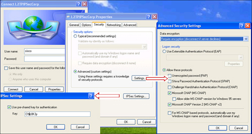
Step 10. Click the Click IPSec Settings, check Use Pre-shared Key for Authentication, and type in the preshared key to set the preshared key. As shown in Figure 17-27, a preshared key of C1@c0K3y is used. Click OK after specifying a key.
Step 11. Click the Networking tab and select L2TP IPSec VPN under the Type of VPN drop-down menu. Click OK to complete this configuration.
Step 12. Specify a username and password and then click Connect to start an L2TP over IPSec connection to the security appliance.
Tip
For more information on how to fine-tune L2TP over IPSec policies on the Windows endpoints, please refer to the Microsoft’s knowledge article 240262 at http://support.microsoft.com/default.aspx?scid=kb;EN-US;q240262
Deployment Scenarios
The ASA VPN solution can be deployed in many different ways. In this section, we cover two design scenarios for ease of understanding:
• Load balancing with Cisco IPSec clients and site-to-site integration
• L2TP over IPSec with traffic hairpinning
Note
The design scenarios discussed in this section should be used solely to reinforce learning. They should be used for reference purposes only.
Load Balancing of Cisco IPSec Clients and Site-to-Site Integration
SecureMe’s headquarters office in Chicago wants to deploy Cisco ASA to be used for remote-access VPN tunnels that will support about 20,000 users. However, SecureMe wants to make sure that users do not overburden the system and therefore wants to use two security appliances in load-balancing mode. SecureMe also wants to terminate a site-to-site tunnel on one of the security appliances. Figure 17-28 shows SecureMe’s network topology in Chicago.
Figure 17-28 SecureMe’s Remote-Access Topology in Chicago
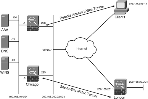
The security requirements for SecureMe’s Chicago office are as follows:
• Load balance Cisco IPSec VPN connections across two Cisco ASA devices.
• Use UDP encapsulation if a NAT device exists between the VPN devices.
• Use a RADIUS server as the external database for user lookup.
• Encrypt only the traffic destined for 192.168.0.0/16.
• Configure a site-to-site VPN tunnel to the London ASA.
• Assign the DNS and WINS server addresses as 192.168.10.10 and 192.168.10.20, respectively.
To meet these requirements, split tunneling is proposed for the Cisco VPN client so that traffic destined to 192.168.0.0/16 is encrypted. NAT-T, which is enabled by default, is to be used for UDP encapsulation.
Configuration Steps Through ASDM
The relevant configuration through ASDM is discussed below. These configuration steps assume that you have IP connectivity from the ASDM client to the management IP address of the security appliances. The management IP address of the Chicago ASA is 172.18.82.64:
Step 1. Launch the IPSec VPN Wizard by clicking Wizards in the toolbar and then selecting IPSec VPN Wizard. ASDM launches the VPN Wizard with the option to choose a VPN tunnel type. Select Remote Access as the VPN tunnel type and select outside from the drop-down menu in the VPN Tunnel Interface field. Make sure that Enable Inbound IPSec Sessions to Bypass Interface Access option is enabled to bypass ACL check for the decrypted traffic. Click Next.
Step 2. In the next window, select Cisco VPN Client, Release 3.x or higher and click Next.
Step 3. Select Pre-shared Keys as the authentication method and specify C!$c0K3y. Under Tunnel Group, specify SecureMeIPSec as the tunnel name. Click Next.
Step 4. In the next window, the wizard prompts you to select a user authentication mechanism. Use an external server such as RADIUS by selecting Authenticate Using an AAA Server Group. If a server is not defined, you can click New and define a new external authentication server group called Radius, located toward the inside interface at 192.168.10.100 with a shared secret of C1$c0123.
Step 5. If a pool of addresses is not currently defined, you can click New and specify a name of IPPool with the start address of 192.168.32.1 and the end address of 192.168.64.254 with a mask of 255.255.224.0. Click Next.
Step 6. Configure the DNS and WINS server addresses of 192.168.10.10 and 192.168.10.20 respectively. Define securemeinc.com as the default domain name. Click Next to specify an IKE policy.
Step 7. Select an IKE policy that uses AES-256 for encryption, SHA for authentication, and DH group 5 for key generation. Click Next.
Step 8. In the next IPSec policy window, select the inside interface and specify 192.168.0.0/16 as Address and then click Add. Select Enable Split Tunneling to Let Remote Users to turn on split-tunneling. Uncheck the Enable Perfect Forwarding Secrecy (PFS) box. Click Next to continue.
Step 9. The VPN Wizard shows you a summary of all the features and configurations you have set. After you have verified the configuration, click Finish to push the configuration to the security appliance.
Step 10. Before you configure load-balancing, enable ISAKMP on the private (inside) interface so that the load-balancing packets can be encrypted. Navigate to Configuration > Remote Access VPN > Network (Client) Access > IPSec Connection Profiles and select the Allow Access option for the inside interface.
Step 11. Next, configure load balancing by navigating to Configuration > Remote Access VPN > Load Balancing. Define the following attributes to enable load-balancing:
• Participate in Load Balancing Cluster: Checked
• Cluster IP address: 209.165.200.227
• UDP Port: 9023
• Enable IPSec Encryption: Checked
• IPSec shared secret: C1$c0123
• Public Interface: Outside
• Private Interface: Inside
• Priority: 9
Step 12. Launch the IPSec VPN Wizard again by clicking Wizards in the toolbar and then selecting IPSec VPN Wizard. ASDM launches the VPN Wizard with the option to choose a VPN tunnel type. Select Site-to-Site as the VPN tunnel type and select outside from the drop-down menu in the VPN Tunnel Interface field. Make sure that the Enable Inbound IPSec Sessions to Bypass Interface Access option is enabled to bypass ACL check for the decrypted traffic. Click Next.
Step 13. In the next window, specify 209.165.201.1 as the Peer IP Address. Select Pre-shared Key as the authentication protocol and specify C!Sc0K3y as the preshared key. Click Next.
Step 14. Select an IKE policy that uses AES-256 for encryption, SHA for authentication, and DH group 5 for key generation. Click Next.
Step 15. Select an IPSec rule policy that uses AES-256 for encryption, SHA for authentication. Disable PFS and click Next.
Step 16. In the next Host and Network policy window, select action Protect and then 192.168.10.0/24 as Local Networks and 192.168.30.0/24 as the Remote Networks. Select Exempt ASA Side Host/Network from Address Translation on the inside interface. Click Next to continue.
Step 17. The VPN Wizard shows you a summary of all the features and configurations you have set. After you have verified the configuration, click Finish to push the configuration to the security appliance.
Configuration Steps using CLI
Example 17-31 shows the complete configuration of SecureMe’s Cisco ASA in Chicago to meet the design requirements.
Example 17-31 Configuration to Load balance Cisco IPSec Clients with Site-to-Site

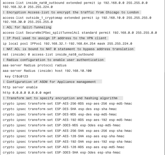

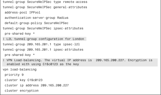
L2TP over IPSec with Traffic Hairpinning
SecureMe has recently installed a new Cisco ASA in its Chicago office to provide VPN access to its remote and home users. Figure 17-29 shows SecureMe’s network topology in Chicago.
Figure 17-29 SecureMe’s Remote-Access Topology for L2TP over IPSec
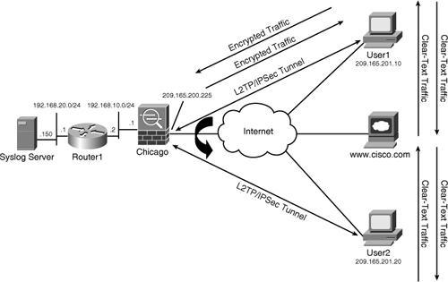
The security requirements for SecureMe are as follows:
• Encrypt all traffic leaving the remote-access clients. Don’t install any IPSec Clients on the workstations.
• Allow VPN clients to communicate with each other.
• Allow VPN clients to access the Internet.
• Use local database for user authentication.
• Log all the system-generated syslog messages to a server.
To meet these requirements, SecureMe has decided to use L2TP over IPSec and the IPSec hairpinning feature. Access to the Internet will be provided by translating the VPN pool of addresses to the public IP address of the security appliance.
Configuration Steps Through ASDM
The relevant configuration through ASDM is described here. These configuration steps assume that you have IP connectivity from the ASDM client to the management IP address of the security appliances. The management IP address of the Chicago ASA is 172.18.82.64.
Step 1. Launch the IPSec VPN Wizard by clicking Wizards in the toolbar and then selecting IPSec VPN Wizard. ASDM launches the VPN Wizard with the option to choose a VPN tunnel type. Select Remote Access as the VPN tunnel type and select outside from the drop-down menu in the VPN Tunnel Interface field. Make sure that the Enable Inbound IPSec Sessions to Bypass Interface Access option is enabled to bypass ACL check for the decrypted traffic. Click Next.
Step 2. In the next window, select Microsoft Windows Client using L2TP over IPSec. Specify MS-CHAP-V1 and MS-CHAP-V2 as the PPP authentication protocols. Click Next.
Step 3. Select Pre-shared Keys as the authentication method and specify C!$c0K3y. Click Next.
Step 4. In the next window, select Authenticate Using the Local User Database. After you click Next, ASDM prompts you to add any additional users that you want to declare.
Step 5. If a pool of addresses is not currently defined, you can click New and specify a name of IPPool with the start address of 192.168.50.1 and the end address of 192.168.50.100 for the new pool of addresses. Select 255.255.255.0 as the subnet mask. Click Next.
Step 6. Configure the DNS and WINS server addresses of 192.168.10.10 and 192.168.10.20 respectively. Define securemeinc.com as the default domain name. Click Next to specify an IKE policy.
Step 7. Select an IKE policy that uses AES-256 for encryption, SHA for authentication, and DH group 5 for key generation. Click Next.
Step 8. In the next IPSec Settings window, you do not specify any networks in the selected Network/Host list. Uncheck the Enable Perfect Forwarding Secrecy (PFS) box. Click Next to continue.
Step 9. The VPN Wizard shows you a summary of all the features and configurations you have set. After you have verified the configuration, click Finish to push the configuration to the security appliance.
Step 10. To allow traffic hairpinning, navigate to Configuration > Device Setup > Interfaces and select Enable Traffic Between Two or More Hosts Connected to the Same Interface.
Step 11. Create a NAT rule to translate the 192.168.50.0/24 (pool of addresses) to the outside IP address of Cisco ASA. Navigate to Configuration > Firewall > NAT Rules > Add > Add Dynamic Rules, click the Manage button, and then click Add under Manage Global Pool. Specify the following attributes to define the outside interface as the translated address:
• Interface: Outside
• Port Address Translated (PAT) Using IP address of the Interface: Selected and added under Addresses Pool. Click OK when you are finished.
Step 12. Navigate to Configuration > Firewall > NAT Rules > Add > Add Dynamic NAT Rule and define the following attributes for traffic going to Chicago ASA:
Original Interface: Outside
Source: 192.168.50.0/24
Translated: Select Pool ID 1, defined in the previous step
Step 13. Navigate to Configuration > Device Management > NAT Rules > Logging > Syslog Server and click Add. Specify the following under
Interface: inside
IP Address: 192.168.20.150
Protocol: UDP, Port: 514. Click OK when done.
Step 14. Navigate to Configuration > Device Management > Logging > Logging Filters, select Syslog Servers, and click Edit. Under Filter on severity, choose Informational from the drop-down menu.
Step 15. Navigate to Configuration > Device Management > Logging > Syslog Setup. Select Include Timestamps in Syslogs to add timestamps when syslogs are generated.
Configuration Steps Through CLI
Example 17-32 shows the relevant configuration to achieve the goals listed earlier.
Example 17-32 Configuring L2TP over IPSec with Traffic Hairpinning
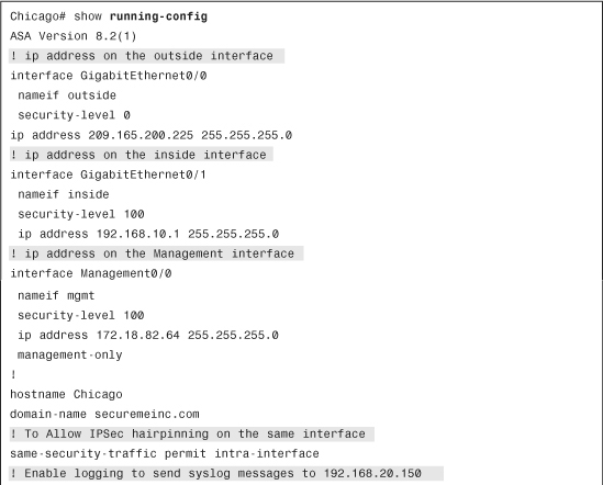
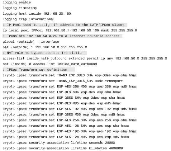

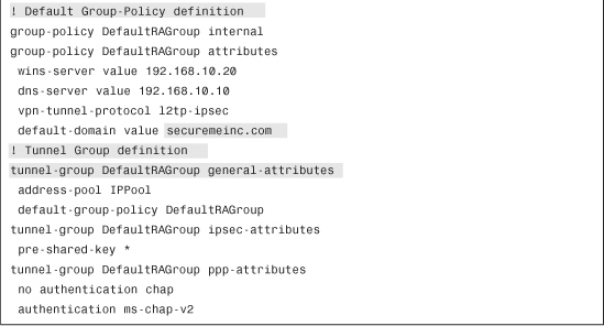
Monitoring and Troubleshooting Cisco Remote-Access VPN
Cisco ASA comes with a number of show commands to check the health and status of the IPSec tunnels. For troubleshooting purposes, there is a rich set of debug commands to isolate the IPSec-related issues.
Monitoring Cisco Remote Access IPSec VPNs
To monitor the IPSec sessions through ASDM, navigate to Monitoring > VPN > VPN Statistics > Sessions and check how many active IPSec tunnels are established on the security appliance. The security appliance shows you all the active VPN sessions, including the clientless and AnyConnect SSL VPN client connections. As shown in Figure 17-30, an active IPSec connection is created by a user called cisco. The user computer’s assigned IP address is 192.168.60.1, and the negotiated encryption type is IKE IPSec AES128. The user is connected for almost 25 seconds. Should you prefer to get detailed information about a user’s connection, select that specific user session and then click the Details button.
Figure 17-30 Monitoring IPSec Sessions Through ASDM

Using the CLI, you can find similar information by using the show vpn-sessiondb detail command, as shown in Example 17-33.
Example 17-33 show vpn-sessiondb detail Command Output
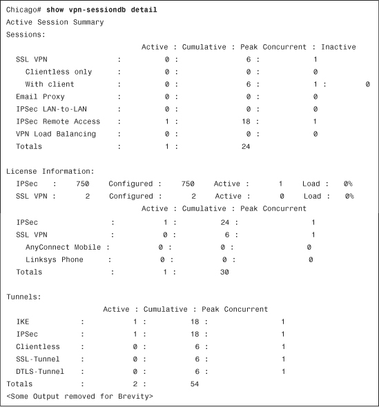
To monitor specific information about the remote users, you can use the show vpn-sessiondb remote command. In Example 17-34, an IPSec session for user ciscouser is displayed. The public IP address of the client is 209.165.201.10, whereas the negotiated address is 192.168.50.1. The security appliance has received 18,279 bytes of traffic while it has transmitted 19,876 bytes of data to the client. The security appliance has enforced policies from a user group called IPSecGroupPolicy. The user is connected for about 12 minutes and 20 seconds.
Example 17-34 show vpn-sessiondb remote Command Output
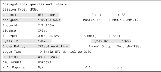
If you want to see if the IPSec tunnels are working and passing traffic, start by looking at the status of Phase 1 SA. Type show crypto isakmp sa detail, as demonstrated in Example 17-35. If the ISAKMP negotiations are successful, you should see the state as AM_ACTIVE.
Example 17-35 show crypto isakmp sa detail Command Output
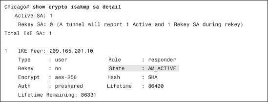
You can also check the status of the IPSec SA by using the show crypto ipsec sa command, as shown in Example 17-36. This command displays the negotiated proxy identities, along with the actual number of packets encrypted and decrypted by the IPSec engine.
Example 17-36 Output of show crypto ipsec sa Command
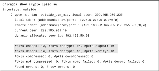
You can check the status of a hardware encryption card with the show crypto accelerator statistics command. In Example 17-37, the important output from this command is shown, which displays the counter information, such as the number of packets going through the encryption card.
Example 17-37 show crypto accelerator statistics Command Output
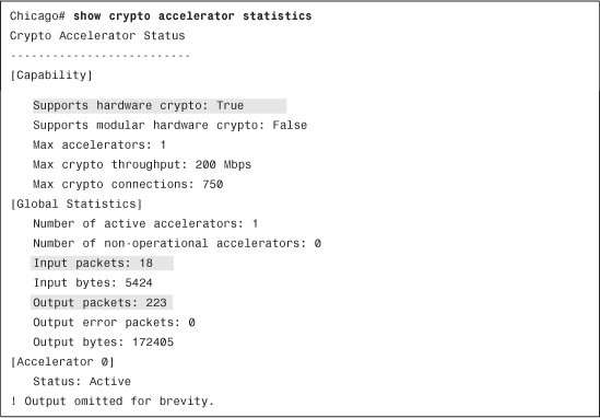
Cisco ASA can display global IKE and IPSec counter information, which is helpful in isolating VPN connection problems. Information such as the number of total requests, the number of total SAs created, and the number of failed requests is useful to determine the failure rate for IKE and IPSec SAs in the security appliance. As shown in Example 17-38, you can view this information by using the show crypto protocol statistics ikev1 and show crypto protocol statistics ipsec command.
Example 17-38 Output of show crypto protocol statistics ikev1 Command
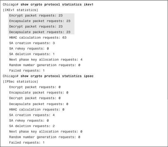
Troubleshooting Cisco IPSec VPN Clients
If the IPSec tunnel is not working for some reason, make sure that you have the proper debug command turned on. The following are the two most important to look at:
• debug crypto isakmp [debug level 1-255]
• debug crypto ipsec [debug level 1-255]
By default, the debug level is set to 1. You can increase the severity level up to 255 to get detailed logs. However, in most cases, setting this to 127 provides enough information to determine the root cause of an issue.
Refer to Figure 17-18 and look at the tunnel negotiation between the Cisco ASA and the VPN client located at 209.165.201.10. To enforce learning, the following debugs have been enabled:
• debug crypto isakmp 127
• debug crypto ipsec 127
As mentioned in Chapter 1, “Introduction to Security Technologies,” the tunnel negotiations opens with an exchange of ISAKMP proposals. The security appliance shows the tunnel group, SecureMeIPSec in this case, to which the VPN client is trying to connect. If the proposal is acceptable, the Cisco ASA displays a message indicating that the IKE SA proposal is acceptable, as shown in Example 17-39.
Example 17-39 debug Output to Show ISAKMP Proposal Is Acceptable
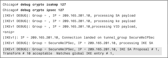
If the proposal is acceptable, the VPN devices try to discover whether they are NAT-T capable and if there is an address-translation device between them. If NAT-T is not negotiated or a NAT/PAT device is not detected, they display the Remote End Is NOT Behind a NAT Device. This End Is NOT Behind a NAT Device message, as shown in Example 17-40.
Example 17-40 debug Output to Show NAT-T Discovery Process

After NAT-T negotiations, Cisco ASA prompts the user to specify user credentials. Upon successful user authentication, the security appliance displays a message indicating that the user (ciscouser in this example) is authenticated, as shown in Example 17-41.
Example 17-41 debug Output to Show User Is Authenticated
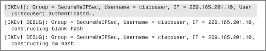
The client requests mode-config attributes by sending a list of client-supported attributes, as shown in Example 17-42. Cisco ASA replies back with all its supported attributes and the appropriate information.
Example 17-42 debug Output to Show Mode-Config Requests
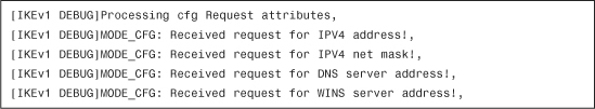
After pushing down the attributes, Cisco ASA displays the “PHASE 1 COMPLETED” message, indicating that the ISAKMP SA is successfully negotiated, as demonstrated in Example 17-43.
Example 17-43 debug Output to Show Phase 1 Negotiations Are Completed
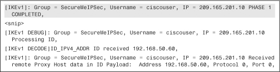
After completing Phase 1 negotiations, the VPN peers try to negotiate Phase 2 SAs by exchanging the proxy identities and the IPSec Phase 2 proposal. If they are acceptable, Cisco ASA displays a message indicating that the IPSec SA proposal is acceptable, as shown in Example 17-44.
Example 17-44 debug Output to Show Proxy Identities and Phase 2 Proposal Are Accepted
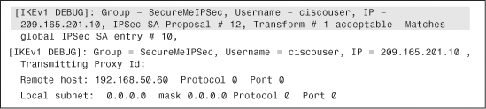
After accepting the transform set values, both VPN devices agree on the inbound and outbound IPSec SAs, as shown in Example 17-45. After the IPSec SAs have been created, both VPN devices should be able to pass traffic bidirectionally across the tunnel.
Example 17-45 debug Output to Show IPSec SAs Are Activated
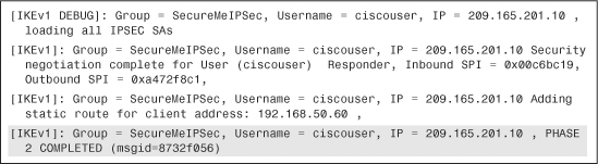
Summary
Using the remote-access methods available with Cisco ASA, security administrators can deploy Cisco ASA into almost any network topology. The Cisco IPSec VPN solution is available for remote users who want to access their enterprise network over a secure VPN connection as if they were directly connected to it. The L2TP over IPSec solution is available for those customers who do not wish to install any IPSec client software to the end machines. To reinforce learning, many different deployment scenarios were discussed, along with their configurations. This chapter covered extensive show and debug commands to assist in troubleshooting complicated remote-access IPSec VPN deployments.