Chapter 16. Site-to-Site IPSec VPNs
Corporations continuously expand their operations by adding remote offices. These offices need network connectivity back to the corporate network for data transfer and resource access. Network administrators must evaluate the security policies of an enterprise to develop secure channels to connect all remote offices. This includes selecting not only the proper network hardware platforms but also the appropriate WAN technology to interconnect the branch and small offices. Some point-to-point WAN technologies include Frame Relay, Integrated Services Digital Network (ISDN), and Asynchronous Transfer Mode (ATM). Though these technologies do provide connectivity between locations, they are not very cost effective. Corporations look for ways to cut costs for increased profitability.
Network professionals can reduce the high maintenance cost of point-to-point WAN links by using the IPSec VPN tunnel in site-to-site mode. They can use broadband connections, including digital subscriber line (DSL) or cable modem, to achieve Internet connectivity at a considerably cheaper rate, and then they can deploy IPSec VPN on top of that to connect the remote locations to the central site. This enables them to accomplish the following goals in a cost-effective manner:
• Internet access for clear-text traffic
• Intranet connectivity over a secure VPN tunnel
This chapter focuses on configuring, deploying, monitoring, and troubleshooting site-to-site IPSec tunnels on the Cisco Adaptive Security Appliances. It discusses a preconfiguration checklist, configuration steps, and different design scenarios. This chapter also discusses how to monitor the IPSec site-to-site tunnel to make sure that the traffic is flowing flawlessly. If the IPSec VPN is having connectivity issues, the chapter provides extensive troubleshooting help later in this chapter.
Preconfiguration Checklist
As discussed in the VPN section of Chapter 1, “Introduction to Security Technologies,” IPSec can use Internet Key Exchange (IKE) for key management and tunnel negotiation. IKE uses a combination of different Phase 1 and Phase 2 attributes that are negotiated between the peers. If any one of the attributes is misconfigured, the IPSec tunnel fails to establish. It is therefore highly recommended that security professionals understand the importance of a preconfiguration checklist and discuss it with other network administrators in case the far end of the VPN tunnel is managed by a different organization.
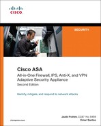
Table 16-1 lists all the possible values of Phase 1 attributes that are supported by Cisco ASA. It also includes the default values for each attribute. Highlighting the options and parameters that will be configured on the other end of the VPN tunnel is recommended.
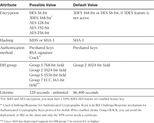
In addition to the IKE parameters, the two IPSec devices also negotiate the mode of operation. Cisco ASA uses main mode as the default mode for the site-to-site tunnels, but it can use aggressive mode if set up accordingly. After discussing Phase 1 attributes, it is important to highlight Phase 2 attributes for the IPsec VPN connection. The Phase 2 security associations (SAs) are used to encrypt and decrypt the actual data traffic. These SAs are also referred as the IPSec SAs. Table 16-2 lists all the possible Phase 2 attributes and their default values, offered by Cisco ASA.
After you determine what Phase 1 and Phase 2 attributes to use, you are ready to configure the site-to-site tunnel.
Note
Advanced Encryption Standard (AES) is a relatively new standard developed by two Belgian cryptographers—Joan Daemen and Vincent Rijmen. AES is expected to replace the aging Data Encryption Standard (DES), which is commonly implemented by the IPSec vendors.
It is a best practice to use AES encryption over DES for enhanced security. Make sure that both IPSec devices support AES before implementing it.
Configuration Steps
There are many ways to set up a static site-to-site tunnel through Cisco ASDM. We emphasize a configuration method that gives you the most control and flexibility in defining a secure connection. This method uses seven configuration steps for successfully defining a site-to-site IPSec tunnel:
Step 4. Define the IPSec policy.
Step 5. Configure the crypto map.
Step 6. Configure traffic filtering (optional).
Step 7. Bypass NAT (optional).
The alternative configuration methods present simple configuration steps; however, they do not offer a lot of control when you need to define specific attributes. The alternative configuration methods are also discussed later in this chapter.
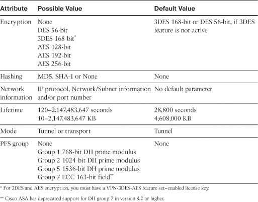
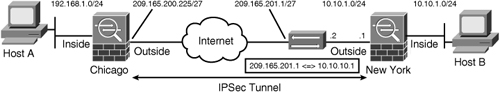
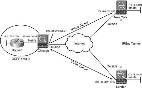
Figure 16-1 illustrates a network topology for SecureMe, Inc. It has two locations: one in Chicago and one in New York. We use the security appliance in Chicago to demonstrate how a site-to-site tunnel can be configured.
Figure 16-1 IPSec Topology for SecureMe Inc.
Step 1: Enable ISAKMP
IKE Phase 1 configuration starts by enabling ISAKMP on the interface that terminates the VPN tunnels. Typically, it is enabled on the Internet-facing or the outside interface. If ISAKMP is not enabled on an interface, then the security appliance does not listen for the ISAKMP traffic (UDP port 500) on that interface. So even if you have a fully configured IPSec tunnel and ISAKMP is not enabled on the outside interface, the security appliance does not respond to a tunnel initialization request.
Navigate to Configuration > Site-to-Site VPN > Connection Profiles and select the Allow Access option next to the interface where you want to terminate the sessions, typically the outside interface. To push this configuration to the security appliance, click the Apply button in ASDM.
Note
When ASDM delivers the commands to enable ISAKMP on an interface, it also pushes down two ISAKMP policies (policy number 5 and 10) that are preconfigured in ASDM. ISAKMP policies are discussed in the next section
Example 16-1 illustrates the command line interface (CLI) output if you want to enable ISAKMP on the outside interface.
Example 16-1 Enabling ISAKMP on the Outside Interface
![]()
Note
IPSec VPN functionality is not available if the Cisco ASA is virtualized. If site-to-site tunnels are required, then the Cisco ASA has to be set up in single mode. This functionality is being considered for future software releases.
There are certain limitations on Cisco ASA’s VPN feature if transparent firewall mode is enabled. Review Chapter 9, “Transparent Firewalls,” for additional details.
Step 2: Create the ISAKMP Policy
After you enable ISAKMP on the interface, create a Phase 1 policy that matches the other end of the VPN connection. Phase 1 policy negotiates the encryption and other parameters that are useful in authenticating the remote peer as well as establishing a secure channel for both VPN peers to use for communication.
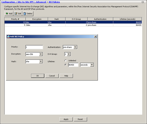
To configure a new ISAKMP policy in the security appliance, navigate to Configuration > Site-to-Site VPN > Advanced > IKE Policies and click Add. ASDM launches a new window where you can specify the following attributes:
• Priority—A number between 1 and 65535. By default, ASDM has priority number 5 and 10 preconfigured. If multiple ISAKMP policies are configured, the Cisco ASA checks the ISAKMP policy with the lowest priority number first. If there is no match, it checks the policy with the next priority number, and so on until all policies have been evaluated. A priority value of 1 is evaluated first, and a priority value of 65535 is evaluated in the last.
• Encryption—Select the appropriate encryption type from the drop-down list. Refer to Table 16-1 for all the supported encryption types. Cisco ASA employs a dedicated hardware encryption accelerator to process IKE requests. It is recommended that you select AES 256-bit encryption because the performance impact is pretty much the same as using a weaker encryption algorithm such as DES.
• Hash—Select the appropriate hash type from the drop-down list. A hashing algorithm provides data integrity by verifying that the packet has not been changed in transit. You have the option to use SHA-1 or MD5. It is recommended to use SHA-1 because it provides better security than MD5.
• Authentication—Select the appropriate authentication type from the drop-down list. The authentication mechanism establishes the identity of the remote IPSec peer. You can use Preshared keys for authenticating a small number of IPSec peers, whereas RSA signatures are useful if you are authenticating a large number of peers. Chapter 18 discusses RSA signatures in detail.
• D-H Group—Select the appropriate D-H group from the drop-down list. D-H group is used to derive a shared secret to be used by the two VPN devices.
• Lifetime—Specify the lifetime within which a new set of ISAKMP keys can be renegotiated. You can specify a finite lifetime between 120 and 2147483647 seconds. You can also select unlimited lifetime in case the remote peer does not propose a lifetime. Cisco recommends that you use the default lifetime of 86400 seconds for IKE rekeys.
Figure 16-2 shows that an ISAKMP policy of priority 1 is being added. The encryption method is AES-256, the hashing algorithm is SHA, the authentication mechanism is preshared keys, the D-H group is 2, and the lifetime of 86400 seconds is specified.
Figure 16-2 Defining IKE Policy via ASDM
Note
If the VPN-3DES-AES feature is not enabled, the security appliance allows DES encryption for only the ISAKMP and IPSec policies.
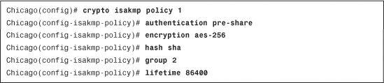
If you prefer the CLI, use the crypto isakmp policy command to define a new policy. Example 16-2 illustrates how to configure an ISAKMP policy for AES-256 encryption, SHA hashing, DH group 2, and preshared keys for authentication with 86,400 seconds as the lifetime.
Example 16-2 Creating an ISAKMP Policy
Note
If one of the ISAKMP attributes is not configured, the security appliance adds that attribute with its default value. To remove an ISAKMP policy, use the clear config crypto isakmp policy command, followed by the policy number to be removed.
Step 3: Set Up the Tunnel Groups
A tunnel group, also known as connection profile, defines a site-to-site or a remote-access tunnel and is used to map the attributes that are assigned to a specific IPSec peer. The remote-access connection profile is used to terminate all types of remote access VPN tunnels such as IPSec, L2TP over IPSec, and SSL VPN. Remote-access VPNs are discussed in Chapters 17, 19, and 20.
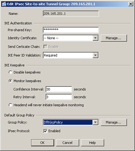
You can configure a tunnel group by choosing Configuration > Site-to-Site VPN > Advanced > Tunnel Groups. Click Add to specify a new tunnel group name. As shown in Figure 16-3, a tunnel group called 209.165.201.1 has been added.
Figure 16-3 Configuration of a Tunnel Group
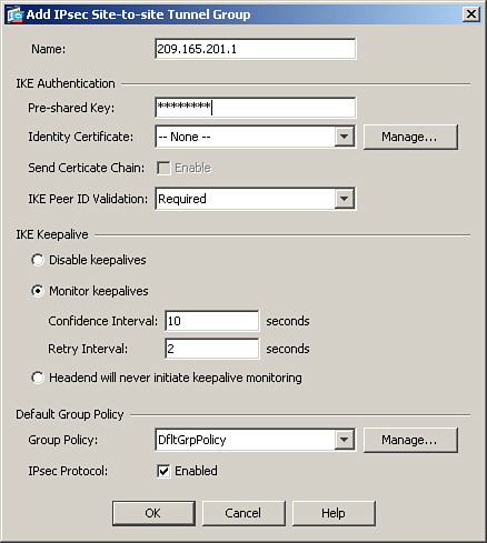
For the site-to-site IPSec tunnels, the IP address of the remote VPN device is used as the tunnel group name. For an IPSec device whose IP address is not defined as the tunnel group, the security appliance tries to map the remote device to the default site-to-site group called DefaultL2LGroup, given that the preshared key between the two devices matches. DefaultL2LGroup is shown in the ASDM configuration, but if you look at the configuration via CLI, it does not appear unless a default attribute within that tunnel group is modified.
Note
The concept of a tunnel group is taken from the VPN 3000 Series Concentrators.
If your ISAKMP policy uses preshared keys as the authentication method, a preshared key must be configured under the tunnel group. It is recommended that you configure a long alphanumeric key with special characters. It will be hard to decode a complex preshared key even if someone tries to break it by using brute force. In Figure 16-3, a preshared key of C!$c0K3y (obfuscated) is set up for the 209.165.201.1 tunnel group.
Example 16-3 illustrates how to configure a site-to-site tunnel group on Cisco ASA if the peer’s public IP address is 209.165.201.1. You define the preshared key under the ipsec-attributes of the tunnel group by using the pre-shared-key command.
Example 16-3 Tunnel Group Definition

Tip
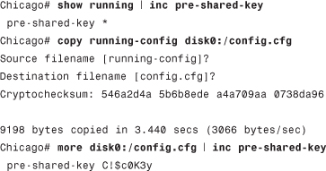
The security appliance obfuscates the preshared key in the configuration for security reasons. If you really want to view the key, copy the running configuration to the flash and then view that configuration by using the more command, as follows:
Step 4: Define the IPSec Policy
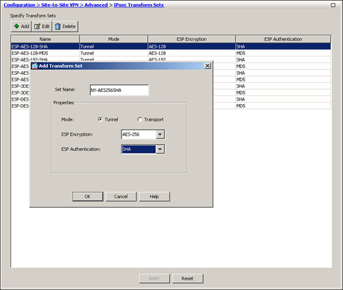
An IPSec transform set specifies what type of encryption and hashing to use for the data packets after a secure connection has been established. This provides data authentication, confidentially, and integrity. The IPSec transform set is negotiated during Quick Mode, discussed in Chapter 1. To configure a new transform set through ASDM, navigate to Configuration > Site-to-Site VPN > Advanced > IPsec Transform Sets and click Add. A new window opens, enabling you to configure the following attributes:
• Set Name—Specify the name for this transform set. This name has local significance and is not transmitted during IPSec tunnel negotiations.
• Encryption—Select the appropriate encryption type from the drop-down list. Refer to Table 16-2 for all the supported encryption types. Cisco ASA employs a dedicated hardware encryption accelerator to process data encryption and hashing. It is recommended that you select AES 256-bit encryption because the performance impact is pretty much the same as using a weaker encryption algorithm such as DES.
• Hash—Select the appropriate hash type from the drop-down list. A hashing algorithm provides data integrity by verifying that the packet has not been changed in transit. You have the option to use SHA-1, MD5, or None. It is recommended to use SHA-1 because it provides better security than MD5.
• Mode—Select the appropriate encapsulation mode from the drop-down list. You have the option to use transport or tunnel mode. Transport is used to encrypt and authenticate the data packets that are originated by the VPN peers. Tunnel mode is used to encrypt and authenticate the IP packets when they are originated by the hosts connected behind the VPN device. In a typical site-to-site IPsec connection, tunnel mode is always used.
In Figure 16-4, a new transform set called NY-AES256SHA is being defined. It is set up to use AES-256 encryption and SHA hashing for data packets. The encapsulation mode is defined as tunnel.
Figure 16-4 Configuring IPSec Transform Set
Note
Cisco ASA supports only ESP as the encapsulation protocol. Support for AH currently is not planned.
Example 16-4 shows how an IPSec transform set can be configured through the CLI.
Example 16-4 Transform Set Configuration

Note
Cisco ASDM has ten predefined IPSec transform sets. You do not have to define a new transform set if you want to use a predefined transform set.
Step 5: Create a Crypto Map
After you have configured both Phase 1 and Phase 2 policies, create a crypto map so that these policies can be applied to a static site-to-site IPsec connection. A crypto map instance is considered complete when it has the following three parameters:
• At least one transform set
• At least one VPN peer
• An encryption ACL
Crypto map uses a priority number (or sequence number) to define an IPSec instance. Each IPSec instance defines a VPN connection to a specific peer. You can have multiple IPSec tunnels destined to different peers. If the security appliance terminates an IPSec tunnel from another VPN peer, a second VPN tunnel can be defined, using the existing crypto map name with a different priority number. Each priority number uniquely identifies a site-to-site tunnel. However, the security appliance evaluates the site-to-site tunnel with the lowest priority number first.
Note
Cisco ASA does not support manual keying for IPSec tunnels. Manual keying is vulnerable to security flaws because the VPN peers always use the same encryption and authentication keys.
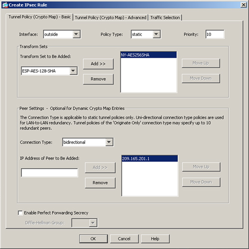
To define a new crypto map, navigate to Configuration > Site-to-Site VPN > Advanced > Crypto Maps, click Add to specify a new map. A new window is launched, enabling you to configure the following attributes:
• Interface—You must select an interface that terminates the IPSec site-to-site tunnel. As mentioned earlier, it is usually the Internet-facing interface. You can apply only one crypto map per interface. If there is a need to configure multiple site-to-site tunnels, you must use the same crypto map with different priority numbers. Please consult deployment scenario 2, “Fully Meshed Topology with RRI,” later in this chapter for an example of multiple crypto map priority numbers.
• Policy Type—If the remote IPSec peer has a static IP address, select Static from the drop-down menu. For a remote static peer, the local security appliance can initiate as well as respond to an IPSec tunnel request. A “dynamic” policy type is useful if the remote peer receives a dynamic IP address on its outside interface. In this scenario, where the peer is marked as dynamic, it is the peer’s responsibility to initiate the VPN connection; it cannot be initiated by the hub.
• Priority—You must specify the priority number for this site-to-site connection. If multiple site-to-site connections are defined for a particular crypto map, Cisco ASA checks the connection with the lowest priority number first. A priority value of 1 is evaluated first; priority value of 65535 is evaluated last.
• Transform Sets—Select a predefined transform set from the drop-down menu. You can select multiple transform sets. In this case, the security appliance sends all the configured transform sets to its peer if it is initiating the connection. If the security appliance is responding to a VPN connection from the peer, it matches the received transform sets with the locally configured transform sets and chooses one to utilize for the VPN connection. You can add up to 11 transform sets here.
• Connection Type—If you want either VPN peers to initiate an IPSec tunnel, select Bidirectional from the drop-down menu. For the other option, refer to the “Connection Type” section under “Modifying Default Parameters” later in this chapter.
• IP Address of Peer to Be Added—Specify the IP address of the remote VPN peer. Typically, it is the public IP address of the remote VPN device.
• Enable Perfect Forward Secrecy—If you want to enable perfect forward secrecy (PFS), enable this option and specify the Diffie-Hellman group you want to use. For more information on PFS, consult it under the “Advanced Features” section later in this chapter.
In Figure 16-5, a new crypto map is being defined with a priority number of 10. This crypto map is marked as static, and the outside interface is designated as the VPN termination point. The IPSec transform set, defined in the previous step, is mapped to this map, whereas the remote VPN peer’s public IP address is 209.165.201.1. If the security appliance needs to initiate a tunnel, it will contact the remote VPN peer, using this IP address.
Figure 16-5 Defining a New Crypto Map
As mentioned earlier, a crypto map is not complete until you define an ACL for the interesting traffic that needs to be encrypted. When a packet enters the security appliance, it gets routed based on the destination IP address. When it leaves the interface, which is set up for a site-to-site tunnel, the encryption engine intercepts that packet and matches it against the encryption access control entries (ACE) to determine whether it needs to be encrypted. If a match is found, the packet is encrypted and then sent out to the remote VPN peer.
An ACL can be as simple as permitting all IP traffic from one network to another or as complicated as permitting traffic originating from a unique source IP address on a particular port destined to a specific port on the destination address.
Note
The IPSec connection between Cisco ASA and other vendors may or may not work because Cisco adheres to IPSec industry standards and other vendors may have their own implementation of the standards.
Additionally, deploying complicated crypto ACLs, using TCP or UDP ports, is not recommended. Many IPSec vendors do not support port-level encryption ACLs.
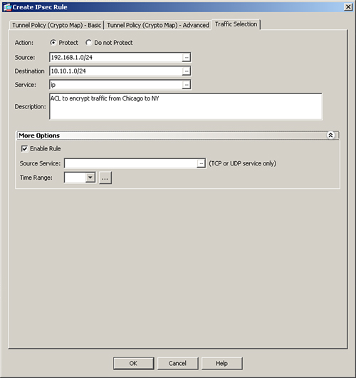
To create a new encryption ACL, select the Traffic Selection tab in the crypto map window, to specify the private networks that you want to encrypt. The required attributes in an encryption ACL are as follows:
• Action—Select the action, either Protect or Do Not Protect, for the traffic matching this ACE. If traffic is protected, the ASA encrypts it.
• Source—Specify the source host IP, network, and object-group. This is the private host or network address of the security appliance.
• Destination—Specify the destination host IP, network, object-group. This is the private host or network address of the remote VPN peer.
• Service—Specify the destination service name such as TCP, UDP, SMTP, HTTP. In a site-to-site IPSec VPN tunnel, the destination service typically includes all IP services.
Note
For more details on the arguments used in an access control entry, consult Table 4-2 in Chapter 4, “Controlling Network Access.”
Encryption ACLs also perform a security check for the inbound encrypted traffic. If a clear-text packet matches one of the encryption ACEs, the security appliance drops that packet and generates a syslog message indicating this incident.
Note
Each ACE creates two unidirectional IPSec SAs. If you have 100 entries in your ACL, then the ASA creates 200 IPSec SAs. Using host-based encryption ACEs is not recommended because that results in a number of ACEs and eventually double the number of SAs. The security appliance uses system resources to maintain the SAs, which may affect overall performance.
Figure 16-6 shows a traffic selection policy that protects (or encrypts in this case) all IP traffic from 192.168.1.0/24 network to 10.10.1.0/24 subnet. A description of ACL to encrypt traffic from Chicago to NY is added as well.
Figure 16-6 Defining an Encryption ACL Within Crypto Map
After a crypto map has been added to ASDM, you may add another ACE to this crypto map by clicking the pull-down Add list and selecting Insert Traffic Selection After option. ASDM launches another window where you can select the private networks to be included in the encryption ACL.
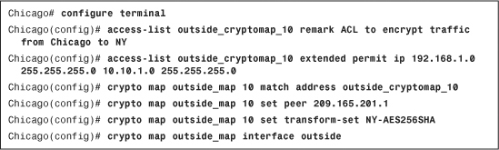
Example 16-5 shows the Chicago ASA is set up to protect all IP traffic sourced from 192.168.1.0 with a mask of 255.255.255.0 and destined to 10.10.1.0 with a mask of 255.255.255.0. The ACL name is outside_cryptomap_10.
Example 16-5 Crypto Map Configuration
The security appliance does not allow IP traffic from the remote private network to connect directly to the ASA’s inside interface. Many enterprises prefer to manage the security appliance using its inside interface from the management network using the VPN connection. You can configure this feature by using the management-access command, discussed later in this chapter.
Step 6: Configure Traffic Filtering (Optional)
Like a traditional firewall, the Cisco ASA can protect the trusted (inside) network by blocking new inbound connections from the outside, unless the ACL explicitly permits these connections. However, by default, the security appliance allows all inbound connections from the remote VPN network to the inside network without an ACL explicitly allowing them. What that means is that even if the inbound ACL on the outside interface denies the decrypted traffic to pass through, the security appliance still allows it.
This default behavior can be changed if you want the outside interface ACL to inspect the IPSec protected traffic. In Figure 16-7, if Host B is allowed to send traffic only to Host A on TCP port 23, you must
Step 1. Define an inbound ACE on the Chicago ASA outside interface ACL
Step 2. Disable the vpn sysopt feature that allows new inbound connections initiated from over the VPN to bypass all access list checks.
Figure 16-7 Filtering Traffic Across a VPN Tunnel
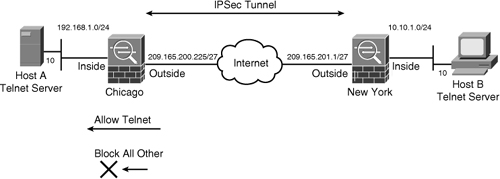
This way, the inbound VPN traffic on port 23 from Host B to Host A is inspected by the interface ACL and then allowed in.
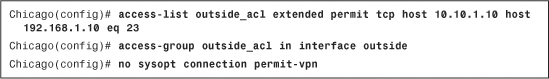
The CLI configuration is illustrated in Example 16-6. The outside ACL allows traffic from a remote host 10.10.1.10 to go to a local host 192.168.1.10 on TCP port 23. The no sysopt connection permit-vpn command enables the security appliance to subject all new inbound connections through the firewall to the configured interface access lists.
Example 16-6 Access List to Allow Decrypted Traffic to Pass Through the ASA
Note
The sysopt connection permit-vpn command is a global command. It is enabled by default and allows the security appliance to bypass the ACL check for all the VPN tunnels, including remote access IPSec as well as SSL VPN tunnels. You can still control traffic by defining authorization access lists on group policies and user policies.
Using ASDM, disable vpn sysopt by navigating to Configuration > Site-to-Site VPN > Advanced > System Options and deselecting the Enable Inbound IPSec Sessions to Bypass Interface Access-Lists option.
Step 7: Bypass NAT (Optional)
In most cases, you do not want to change the IP addresses for the traffic going over the tunnel. If NAT is configured on the security appliance to change the source or destination IP addresses for non-VPN traffic, you can set up the NAT exempt rules to bypass address translation for traffic destined over the VPN tunnels, as discussed in Chapter 4.
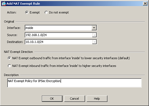
To bypass address translation, you must identify traffic that needs to go over the VPN tunnel and then apply the NAT exemption rule. Using ASDM, navigate to Configuration > Firewall > NAT Rules > Add, select Add NAT Exempt Rule and specify the following information:
• Action—Select the Exempt radio button.
• Interface—Select the inside interface or the interface that you are protecting with the VPN tunnel.
• Source—Specify the local protected network/subnet information.
• Destination—Specify the remote protected network/subnet information.
• NAT Exempt Direction—Select NAT Exempt Outbound Traffic from Interface Inside to Lower Security Interfaces.
• Description—Specify a brief description.
Figure 16-8 shows a NAT exempt policy for the traffic originated from 192.168.1.0/24 to 10.10.1.0/24 on the inside interface.
Figure 16-8 NAT Exempt Policy to Bypass NAT for IPSec Tunnel
Example 16-8 shows the CLI version of the NAT Exempt Policy for IPSec Encryption. The ACL is called inside_nat0_outbound.
Example 16-8 Access List to Bypass NAT

Note
If you do not define a NAT exemption policy and NAT is done for VPN traffic, then the crypto ACL should match the post-NAT (or global) IP addresses.
Alternate Configuration Methods Through ASDM
There are two additional methods by which you can define the site-to-site tunnels. These alternate methods are available if you configure the security appliance through ASDM. They include:
• IPSec Wizard
• Connection Profiles
Defining Site-to-Site Tunnel Through IPSec VPN Wizard
The simplest and easiest way to define a new site-to-site connection is by following the IPSec VPN wizard. You can launch the wizard by clicking Wizards in the toolbar and then selecting IPSec VPN Wizard. ASDM launches the VPN Wizard with the option to choose a VPN tunnel type. Follow these steps to successfully define the site-to-site tunnel:
Step 1. Select Site-to-Site radio button.
Because the remote peer of the site-to-site VPN tunnel resides toward the appliance’s outside interface, select outside from the drop-down menu in the VPN Tunnel Interface field. Make sure that the Enable Inbound IPsec Sessions to Bypass Interface Access option is enabled to bypass ACL check for the decrypted traffic. Click Next to move to the Remote Site Peer window.
Step 2. Specify Peer Information.
In the next window, the VPN wizard prompts you to specify peer information, such as its public IP address and ISAKMP authentication method. Using Figure 16-1 for illustration purposes, the public IP address of the appliance in New York is 209.165.201.1. Use this IP address in the Peer IP Address field. The Tunnel Group Name is also auto-populated with the same IP address. Under Pre-shared Key as the Authentication Method, specify C!$c0K3y. Click Next to move to the IKE Policy window.
Step 3. Select the IKE policy.
Select the appropriate IKE policy for this peer. Use AES-256 for encryption, SHA for authentication, and DH group 5 for key generation to match the configuration with the remote peer. Click Next to move to the IPSec Encryption and Authentication window.
Step 4. Set up the IPSec transform set.
You configure the IPSec transform set by selecting an encryption and authentication algorithm. Use AES-256 for encryption and SHA for hash authentication to match with the configuration of the remote IPSec peer. Do not enable perfect forwarding secrecy (PFS). Click Next to move to the Local and Remote Hosts and Networks window.
Step 5. Identify local and remote networks.
Select the hosts/subnets or networks to be used as the local and remote proxies during the IPSec negotiation. The appliance recognizes all the local and remote networks, if their routes are in the routing table. You can click the ... button to see a list of the local networks. Optionally, you may manually add an address in the IP Address field with the appropriate subnet mask. For the local network, specify 192.168.1.0/24, and for the remote network, specify 10.10.1.0/24. Leave the Exempt ASA Side Host/Network from Address Translation box checked to bypass address translation. Click Next to verify your configuration. If all parameters look accurate, click Finish to complete the VPN Wizard.
Defining a Site-to-Site Tunnel Through Connection Profile
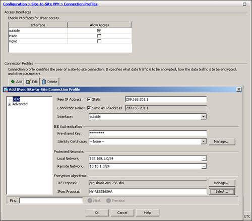
You can also define a Site-to-Site tunnel by adding a new connection profile. First navigate to Configuration > Site-to-Site VPN > Connection Profiles and enable Allow Access on the outside interface under the Access Interfaces option. Click Add under Connection Profiles to define a new Site-to-Site tunnel. ASDM opens a new window where you can specify the following attributes:
• Peer IP Address—Specify the public IP address of the remote VPN device. In most Site-to-Site implementation, you a static IP addresses assigned to the remote VPN device. If this is the case, then make sure that the Static box is checked. If the remote VPN peer receives its IP address dynamically, then uncheck the Static box. The Peer IP address box is grayed out if Static box is unchecked.
• Connection Name—If the static box is checked and you have an IP address defined in the Peer IP Address box, then by default the connection name is the same as the peer IP address box in the static box. If the static box is not enabled, then you can specify a name for this connection in this box.
• Interface—Select the interface that terminates the IPSec tunnel. In most cases, this is the outside interface of the security appliance.
• Pre-shared key—Pre-shared keys remain the most commonly used IKE authentication method in the IPSec Site-to-Site tunnels. If you prefer to use preshared keys as the authentication method, specify a key in this box.
• Identity Certificate—If you would rather use certificates as the IKE authentication method, select an identity certificate from the drop-down menu. Chapter 18, “Public Key Infrastructure (PKI),” covers PKI and certificates in detail.
• Local Network—Select the local network you want to protect by this site-to-site tunnel.
• Remote Network—Select the remote network you want to protect by this site-to-site tunnel.
• IKE Proposal—By default, ASDM selects all the configured IKE proposals in this box. You can manage (edit, add or remove) IKE proposals by clicking the Manage button.
• IPsec Proposal—By default, ASDM shows and selects all the IPSec transform sets. You can select one or more transform sets for an IPSec connection.
After you have all the information specified, click OK to push the configuration to the security appliance. As shown in Figure 16-9, the peer’s IP address is 209.165.201.1 and the connection is terminated on the outside interface. A preshared key of C!$c0K3y is defined as the IKE authentication method. The local network is 192.168.1.0/24, and the remote network of 10.10.1.0/24 is also defined. The IKE and IPSec proposals are pre-share-aes-256-sha and NY-AES256SHA, respectively.
Figure 16-9 Site-2-Site IPSec Definition via Connection Profile
Advanced Features
Cisco ASA provides many advanced features to suit your site-to-site VPN implementations. These features include the following:
• Perfect Forward Secrecy (PFS)
OSPF Updates over IPSec
As discussed in Chapter 5, “IP Routing,” Open Shortest Path First (OSPF) uses the multicast methodology to communicate with its neighbors. IPSec, on the other hand, does not allow encapsulation of the multicast traffic. Cisco ASA solves this problem by enabling you to statically define the neighbors so that unicast OSPF packets can be sent to the remote VPN peer. Refer to Chapter 5 for in-depth coverage of the OSPF neighbor feature.
To enable the security appliance to send the OSPF routing updates over a site-to-site IPsec tunnel, follow these steps:
Step 1. Designate the outside interface (or any IPSec terminating interface) as a non-broadcasting interface. Navigate to Configuration > Device Setup > Routing > OSPF > Interface > Properties tab, select the outside interface, click Edit and uncheck the Broadcast option.
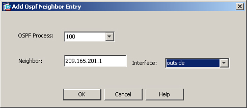
Step 2. Statically add the remote VPN device as an OSPF neighbor. Browse to Configuration > Device Setup > Routing > OSPF > Static Neighbor > Add and select the OSPF process you are using in your network. Specify your IPSec peer’s public address and select the VPN terminating interface. Figure 16-10 illustrates a remote VPN ASA (209.165.201.1) being added as a static OSPF neighbor for OSPF process 100. The OSPF neighbor is located toward the outside interface.
Figure 16-10 OSPF Updates over IPSec
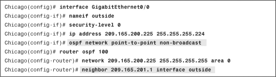
Example 16-9 shows how to set up the outside interface as a nonbroadcast media and specify the remote VPN peer as the OSPF neighbor on the outside interface.
Example 16-9 OSPF Updates over IPSec
Note
The OSPF Update over IPSec feature works only between two Cisco security appliances.
Reverse Route Injection
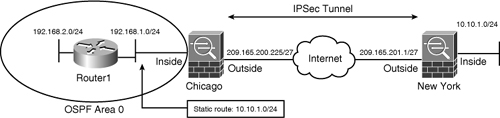
Reverse route injection (RRI) is a way to distribute remote network information into the local network with the help of a routing protocol. With RRI, the Cisco ASA automatically adds static routes about the remote private networks across the tunnel to its routing table and then announces these routes to its neighbors on the local private network, using OSPF. Figure 16-11 shows an IPSec topology that uses OSPF to propagate the remote private network information into the local LAN of the Chicago ASA.
Figure 16-11 Example of RRI in the ASA
To configure RRI through ASDM, modify the crypto map properties by navigating to Configuration > Site-to-Site VPN > Advanced > Crypto Maps. Select your previously configured crypto map, edit its properties, and then select Enable Reverse Route Injection under the Tunnel Policy (Crypto Map)-Advanced tab.
Example 16-10 illustrates a crypto map called outside_cryptomap_10, set up to use RRI.
Example 16-10 Configuration of Reverse Route Injection
![]()
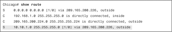
To check whether the ASA is adding the remote network information in its routing table, type show route, as illustrated in Example 16-11.
Example 16-11 Routing Table on the ASA
If you see the static route for the remote private network in the routing table, advertise the static route to the OSPF peers. You can do that within ASDM by browsing to Configuration > Device Setup > Routing > OSPF > Redistribution > Add, selecting the OSPF process you are using, choosing Static under the Protocol option, and then selecting the Use Subnets option. Example 16-12 illustrates the same steps using the CLI.
Example 16-12 OSPF Configuration on the ASA
![]()
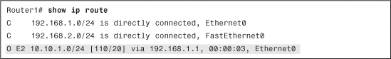
The internal router (Router1) will receive this route and install it in its routing table, as demonstrated in Example 16-13.
Example 16-13 Routing Table on Internal Router
NAT Traversal
Traditionally, the IPSec tunnels fail to pass traffic if there is a PAT device between the peers. By default, IPSec devices use the ESP protocol, which does not have any Layer 4 information and therefore the PAT device ends up dropping the IPSec packet.
Note
Consult Chapter 1 for more information on ESP through PAT implementations.
To remedy this problem, Cisco drafted an IETF standard called NAT Traversal (NAT-T) to encapsulate the ESP packets into a UDP port connection on port 4500 so that any intermediate PAT device would have no trouble translating the encrypted packets. NAT-T is dynamically negotiated if the following two conditions are met:
• Both VPN peers are NAT-T-capable
• There is a NAT or PAT device between the peers
If both conditions are met, VPN peers start their communication using ISAKMP (UDP port 500), and as soon as a NAT or PAT device is detected, switch to UDP port 4500 to complete the rest of their negotiations.
NAT-T is globally enabled on the security appliance by default. In many cases, the NAT/PAT devices time out the NAT-T encrypted connection on UDP port 4500 entries if there is no active traffic passing through them. NAT-T keepalives are used so that the security appliance can send periodic keepalive messages to prevent the entries from timing out on the intermediary devices. You can specify a NAT-T keepalive range between 10 and 3600 seconds with a default keepalive timeout of 20 seconds.
If NAT-T is not enabled for some reason, you can enable it by navigating to Configuration > Site-to-Site VPN > Advanced > IKE Parameters and then checking the Enable IPSec over NAT-T option. If NAT-T is globally enabled, and you do not want one of the peers to negotiate it, you can navigate to Configuration > Site-to-Site VPN > Advanced > Crypto Maps. Select your previously configured crypto map, edit its properties, and then disable the Enable NAT-T option under the Tunnel Policy (Crypto Map)-Advanced tab.
Example 16-14 illustrates how NAT-T is globally enabled with keepalives sent every 30 seconds in the CLI. It also illustrates how NAT-T can be disabled for a particular VPN peer that uses sequence number 10.
Example 16-14 Disabling NAT-T for a Peer
![]()
Tunnel Default Gateway
A Layer 3 device typically has a default gateway that it uses to route packets when the destination address is not found in its routing table. Tunnel default gateway, a concept first introduced in the VPN3000 concentrators, is used to route the packets if they reach the security appliance over an IPSec tunnel and if their destination IP address is not found in the routing table. The tunneled traffic can be either remote access or site-to-site VPN traffic. The tunnel default gateway next-hop address is generally the IP address of the inside router, Router1 (illustrated in Figure 16-11), or any Layer 3 device.
The tunnel default gateway feature is important if you do not want to define routes to your internal networks on the Cisco ASA and you rather want the tunneled traffic to be sent to the internal router for routing.
To set up a tunnel default gateway, navigate to Configuration > Device Setup > Routing > Static Routes > Add. A new window appears where you can add a default route with the gateway IP being the next-hop IP address of the inside route (Router1). Make sure that you enable the Tunneled radio button, as shown in Figure 16-12.
Figure 16-12 Defining a Tunnel Default Gateway
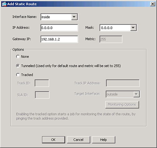
If you prefer to use the CLI, make sure that you add the keyword tunneled to the statically configured default route. Example 16-15 shows the configuration of the appliance with the tunnel default gateway specified as 192.168.1.2, located on the inside interface.
Example 16-15 Tunnel Default Gateway Configuration
![]()
Note
Before you implement the default route tunneled option, you must understand the current restrictions:
• You cannot enable unicast RPF on the egress interface of tunneled route.
• You cannot enable TCP intercept on the egress interface of the tunneled route.
• Many VoIP inspection engines (such as H.323, GTP, MGCP, RTSP, SIP, SKINNY), the DNS inspect engine, and the DCE RPC inspection engine ignore the tunneled route.
• You can define only one default route with the tunneled option.
Management Access
As briefly mentioned earlier in the chapter, Cisco ASA does not allow the remote private network to manage the security appliance if
• The traffic traverses over a VPN tunnel.
• The traffic accesses the inside (or any interface other than the interface through which the VPN traffic entered the firewall) of the security appliance.
This is true even if the inside interface’s IP address is included in the encryption ACL. Many enterprises want to monitor the status of the inside interface over the tunnel to check the appliance’s health. To solve this, enable the “Management Access” feature on the inside interface of the appliance. With this feature turned on, remote devices can use management applications such as SNMP polls, ASDM, Telnet, SSH, ping, HTTPS requests access, syslog messages, and NTP requests.
Enable the feature by browsing to Configuration > Device Management > Management Access > Management Interface and selecting the inside (or any other) interface from the drop-down menu. You can also enable this feature through the CLI by using the management-access command followed by the name of the interface. In Example 16-16, the inside interface is being set up for management access.
Example 16-16 Management Access on the Inside Interface
![]()
Note
You can make only one interface the management access interface.
Perfect Forward Secrecy
Perfect Forward Secrecy (PFS) is a cryptographic technique where the newly generated keys are unrelated to any previously generated key. With PFS enabled, the security appliance generates a new set of keys that are used during the IPSec Phase 2 negotiations. Without PFS, the Cisco ASA uses Phase 1 keys in the Phase 2 negotiations. The Cisco ASA uses Diffie-Hellman group 1, 2, and 5 for PFS to generate the keys. Diffie-Hellman group 1 uses a 768-bit modulus size to generate the keys, whereas group 2 uses 1024 bits and group 5 uses a 1536-bits modulus size. Group 5 is the most secure technique but requires more processing overhead.
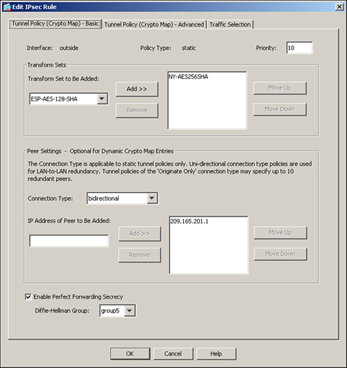
To configure PFS through ASDM, browse to Configuration > Site-to-Site VPN > Advanced > Crypto Maps. Select your previously configured crypto map, edit its properties, and then enable the Enable Perfect Forwarding Secrecy option. Specify a Diffie-Hellman group you want to use for this tunnel. As shown in Figure 16-13, a DH group 5 is used for the PFS option in the crypto map.
Figure 16-13 Enabling PFS for a Tunnel
Example 16-17 illustrates how to enable PFS group 5 for a peer that uses sequence number 10, using the CLI.
Example 16-17 Configuring PFS Group 5 for a Peer
![]()
Modifying Default Parameters
In addition to the advanced features discussed in the preceding section, you can optionally tweak many default parameters to optimize the site-to-site connections. This section discusses these parameters:
• Security association lifetimes
• IPSec and packet fragmentation
Security Association Lifetimes
IPSec security association lifetimes specify when the IPSec peers should renegotiate a new pair of data encryption keys. If you do not specify the IPSec security association lifetimes, the Cisco ASA uses the default values of 28,800 seconds or 4,275,000 KB. Like NAT-T, the IPSec security association lifetimes can be set either globally or per crypto map instance. ASDM, however, does not allow you to configure the global values of security association lifetimes. You must use the CLI to modify the global default values.
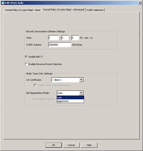
To modify the default IPSec SA lifetimes for a specific crypto map instance, navigate to Configuration > Site-to-Site VPN > Advanced > Crypto Maps. Select your previously configured crypto map, edit its properties, and then specify the new values of the IPSec SA lifetime under the Tunnel Policy (Crypto Map)-Advanced tab. You may want to set lifetime values shorter, such as 4 hours, so that your data encryption keys are negotiated more often. It is useful in those scenarios where you are transferring very confidential and crucial data and you want to regenerate new keys often. You can also modify the IPSec SA volume lifetime in kilobytes so that it negotiates new keys when a specific amount of data has been encrypted by the current keys.
Figure 16-14 illustrates how to modify the IPSec SA lifetime. The current encryption key will expire in either 14,400 seconds (4 hours) or 2,500,000 kilobytes, whichever comes first.
Figure 16-14 Changing IPSec SA Timeout
Example 16-18 illustrates, using the CLI, how to set the IPSec SA to expire in either 14,400 seconds (4 hours) or 2,500,000 kilobytes, whichever comes first.
Example 16-18 Configuring PFS Group 5 for a Peer

Lifetime in seconds can vary between 120 and 2,147,483,647, and lifetime in kilobytes can range from 10 to 2,147,483,647 KB. To configure IPSec SA lifetime globally, use the following CLI syntax:
crypto ipsec security-association lifetime
After you specify both security-association lifetime values (in kilobytes and seconds), they appear as separate CLI commands in the configuration.
Phase 1 Mode
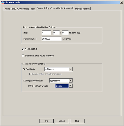
ISAKMP implementation in Cisco ASA, by default, uses main mode for Phase 1 negotiations. If the remote VPN peer initiates a site-to-site tunnel using aggressive mode, the security appliance responds back to the tunnel request in aggressive mode. Aggressive mode has some security weaknesses, so it is recommended to use main mode where possible. This is why the security appliance allows you to disable it globally if you do not want to accept connections that use aggressive mode. Disable aggressive mode by browsing to Configuration > Site-to-Site VPN > Advanced > IKE Parameters and unchecking the Disable Inbound Aggressive Mode Connections option. If you would rather initiate Phase 1 negotiations using aggressive mode, you can change the default behavior by navigating to Configuration > Site-to-Site VPN > Advanced > Crypto Maps, selecting your previously configured crypto map, editing its properties, and then selecting aggressive under the IKE Negotiation Mode drop-down menu in the Tunnel Policy (Crypto Map)-Advanced tab. You must specify the Diffie-Hellman group to be used for initiating the aggressive mode request.
Figure 16-14 and Example 16-19 show you how you can use aggressive mode with DH group 5 to initiate IKE requests.
Example 16-19 Enabling Aggressive Mode for Crypto Map
![]()
Connection Type
The Cisco ASA in the site-to-site tunnel can respond to as well as initiate a VPN connection. This bidirectional default behavior can be changed to answer-only or originate-only mode. For example, if you want to limit the security appliance to just initiate IKE tunnels and never respond to a tunnel request, you can set the connection type to originate-only. This way, if the remote VPN peer tries to initiate the connection, the local appliance will not honor the request. Similarly, if you want the security appliance to accept IKE tunnels only from the peer, then you can set the connection type to answer-only.
Note
If you need to specify multiple peers in your crypto map sequence number for redundancy, you must set your connection type to originate-only mode.
You can change the connection type by navigating to Configuration > Site-to-Site VPN > Advanced > Crypto Maps, selecting your previously configured crypto map, editing its properties, selecting the Tunnel Policy (Crypto Map) - Basic tab and then changing the Connection Type to either originate-only or answer-only. Figure 16-15 illustrates that Chicago ASA’s connection type is set up as originate-only for the peer 209.165.201.1.
Figure 16-15 Changing Connection Type
Example 16-20 illustrates Chicago ASA’s connection type as set up, using the CLI, as originate-only for a peer that uses sequence number 10.
Example 16-20 Configuring Connection Type to Originate-Only for a Peer
![]()
ISAKMP Keepalives
The ISAKMP keepalives feature is a way to determine whether the remote VPN peer is still reachable or there are any lingering SAs (SAs that do not get cleared properly). By default, Cisco ASA starts sending Dead Peer Detection (DPD) packets after it stops receiving encrypted traffic over the tunnel from the peer. If it does not hear from its peer for 10 seconds (confidence interval), it sends out a DPD R_U_THERE packet. It keeps sending the R_U_THERE packets every 2 seconds (the retry interval). If it does not receive R_U_THERE_ACK for four consecutive DPDs polling periods, the security appliance deletes the corresponding ISAKMP and IPSec SAs.
You can also tweak the keepalive parameters to suit your needs. If you have an unreliable connection to the remote VPN peer, you may want to increase the keepalive timer so that it does not timeout the SAs because of connection issues. To change the default IKE keepalive values through ASDM, browse to Configuration > Site-to-Site VPN > Advanced > Tunnel Groups, select your previously defined tunnel group, and edit its properties. Specify the new confidence interval and retry interval in seconds. In Figure 16-16, if the Cisco ASA does not receive encrypted traffic for 30 seconds, it sends out the first DPD packet. It is also configured to send periodic DPDs every 3 seconds if it fails to get an ACK.
Figure 16-16 Changing IKE Keepalive Timeout
To change the IKE keepalive timeout, follow Example 16-22.
Example 16-22 Changing ISAKMP Keepalives
![]()
Some non-Cisco vendors may not understand the DPD packets sent by the security appliance. If you do not want to send DPD messages for a specific peer, disable this feature by navigating to Configuration > Site-to-Site VPN > Advanced > Tunnel Groups, selecting your previously defined tunnel group, editing its properties, and selecting the Disable Keepalives option. Example 16-23 illustrates how to disable ISAKMP keepalives for peer 209.165.201.1.
Example 16-23 Disabling ISAKMP Keepalives
![]()
IPSec and Packet Fragmentation
The outbound maximum transmission unit (MTU) of an Ethernet interface is typically 1500 bytes. As discussed in Chapter 1, IPSec appends headers when it encrypts the data packets. Therefore, when an original packet is the same size or larger than the outbound interface’s MTU, then the packet must be fragmented so that IPSec can successfully add its headers. Most of the VPN devices perform fragmentation after encryption. Therefore, the other end of the VPN tunnel is responsible for defragmenting and decrypting the packet. The problem with this approach is that packet reassembly is typically done at the processer level, which utilizes extra CPU cycles for this additional task. If the packets are fragmented before they are encrypted, then the other side of the tunnel is responsible only for decrypting the packets, and the destination host will be responsible for defragmenting them. Thus you save the CPU overhead of defragmentation on the security appliance by delegating this task to the end hosts.
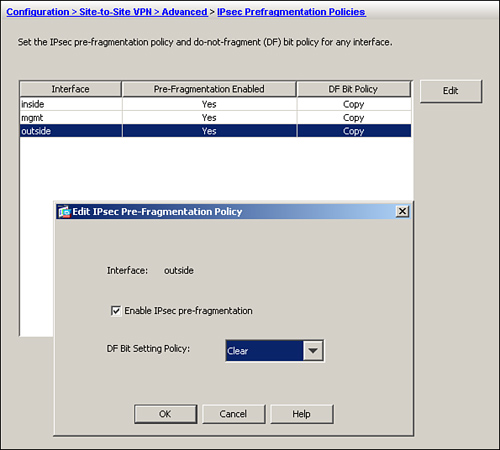
The Cisco security appliance, by default, allows fragmentation to occur before packets are encrypted. However, if the do-not-fragment (DF) bit is set on the packets, the security appliance retains the DF-bit and the original packet does not get fragmented. Therefore, if large packets with the DF-bit set try to pass through the security appliance, they are dropped. This may be something you do not want in your network.
To change the default behavior, browse to Configuration > Site-to-Site VPN > Advanced > IPsec Prefragmentation Policies, select the VPN terminating interface (usually the outside interface), edit the attribute values, and select Clear under the “DF Bit Setting Policy.”
Figure 16-17 illustrates how to clear the DF-bit on the encrypted packets egressing the outside interface over the VPN tunnel.
Figure 16-17 Clearing DF-Bit for IPSec Packets
Example 16-24 illustrates how to clear the DF-bit for the packets going over the IPsec tunnel. It also shows how to enable fragmentation before encryption if this behavior was changed earlier.
Example 16-24 Clearing the DF-Bit for IPSec packets
![]()
Deployment Scenarios
The ASA VPN solution can be deployed in many different ways. This section covers two of these deployment scenarios:
• Single site-to-site tunnel configuration using NAT-T
• Fully meshed topology with RRI
Note
The deployment scenarios discussed in this section should be used solely to reinforce learning. They should be used for reference purposes only.
Single Site-to-Site Tunnel Configuration Using NAT-T
Figure 16-18 shows a network topology of SecureMe, which has deployed two Cisco ASAs—one at the hub site in Chicago, and the other at its New York location. The New York ASA is connected to the Internet via a broadband connection that is set up to perform PAT for the traffic passing through it. Because the PAT device does not allow passing of the non-TCP and non-UDP traffic, the security appliances are set up for NAT-T. During the ISAKMP negotiations, the security appliances will detect that a PAT device exists between them, therefore forcing the traffic to be encapsulated into UDP port 4500. These security appliances are set up to send NAT-T keepalives every 50 seconds to keep the connection entries active. The administrator wants to implement the strongest available encryption and hashing algorithm for a secure connection.
Figure 16-18 SecureMe Network Using NAT-T
Configuration Steps Through ASDM
The relevant configuration through ASDM is discussed below. These configuration steps assume that you have IP connectivity from the ASDM client to the management IP address of the security appliances. 172.18.82.64 is the management IP address of the Chicago ASA, and 172.18.101.164 is the IP address of the New York ASA. Because all devices need to have identical encryption and hashing policies, the following configurations steps are common on both devices:
Step 1. To enable IKE processing on the outside interface, navigate to Configuration > Site-to-Site VPN > Connection Profile and select the Allow Access option under the Outside access interface.
Step 2. Create an IKE Phase 1 policy by navigating to Configuration > Site-to-Site VPN > Advanced > IKE Policies > Add and specifying the following attributes:
• Priority: 1
• Authentication: pre-share
• D-H Group: 5
• Hashing: SHA
• Lifetime: 86400 seconds. Click OK when you are finished.
Step 3. Create an IPSec transform set by navigating to Configuration > Site-to-Site VPN > Advanced > IPSec Transform Sets > Add and specifying the following attributes:
• Set Name: AES-SHA
• Mode: Tunnel
• ESP Encryption: AES-256
• ESP Authentication: SHA. Click OK when you are finished.
Make sure that the Enable Inbound IPSec Sessions to Bypass Interface Access Lists. Group Policy and Per-User Authorization Access Lists Still Apply to the Traffic option is enabled under Configuration > Site-to-Site VPN > Advanced > System Options. It is required to bypass traffic filtering of the encrypted traffic through the interface ACL checks.
Configuration of Chicago ASA
Step 1. Define a Tunnel Group by navigating to Configuration > Site-to-Site VPN > Advanced > Tunnel Group > Add and specifying the following attributes:
• Name: 209.165.201.1
• Preshared Key: C1$c0123
• Make sure that IPSec Protocol check box is enabled. Leave all other options to their default values and click OK when you are finished.
Step 2. Navigate to Configuration > Site-to-Site VPN > Advanced > IKE Parameters and select the Enable IPsec over NAT-T option. The NAT Keepalive should be 50 seconds to meet SecureMe requirements.
Step 3. Next, navigate to Configuration > Site-to-Site VPN > Advanced > Crypto Maps > Add, click the Tunnel Policy (Crypto Map)- Basic tab, and specify the following attributes:
• Interface: outside
• Policy Type: Static
• Priority: 1
• Transform Set to be Added: AES-SHA and click Add>>.
• Connection Type: bidirectional
• IP Address of Peer to be Added: 209.165.201.1 and click Add>>.
Step 4. To specify the interesting traffic for encryption, click the Traffic Selection tab of the crypto map properties and define the following attributes:
• Action: Protect
• Source: 192.168.1.0/24
• Destination: 10.10.1.0/24
• Service: IP
• Description: To Encrypt Traffic from 192.168.1.0/24 to 10.10.1.0/24. Click OK when you are finished.
Step 5. If NAT-Control<$IASDM (Adaptive Security Device Manager);site-to-site IPSec VPN deployments;single site-to-site tunnel configuration via NAT Traversal> is enabled, navigate to Configuration > Firewall > NAT Rules > Add > Add NAT Exempt Rule and define the following attributes:
• Action: Exempt
• Interface: inside
• Source: 192.168.1.0/24
• Destination: 10.10.1.0/24
• NAT Exempt Direction: NAT Exempt outbound traffic from interface ‘inside’ to lower security interfaces (default).
• Description: To Bypass NAT from 192.168.1.0/24 to 10.10.1.0/24. Click OK when you are finished.
Configuration of New York ASA
Step 1. Define a Tunnel Group by navigating to Configuration > Site-to-Site VPN > Advanced > Tunnel Group > Add and specifying the following attributes:
• Name: 209.165.200.225
• Preshared Key: C1$c0123
• Make sure that the IPSec Protocol check box is enabled, leave all other options at their default values, and click OK when you are finished.
Step 2. Navigate to Configuration > Site-to-Site VPN > Advanced > IKE Parameters and select the Enable IPsec over NAT-T option. The NAT Keepalive should be 50 seconds to meet SecureMe requirements.
Step 3. Next, navigate to Configuration > Site-to-Site VPN > Advanced > Crypto Maps > Add, click the Tunnel Policy (Crypto Map)- Basic tab, and specify the following attributes:
• Interface: outside
• Policy Type: Static
• Priority: 1
• Transform Set to be Added: AES-SHA and click Add>>.
• Connection Type: bidirectional
• IP Address of Peer to be Added: 209.165.200.225 and click Add>>
Step 4. To specify the interesting traffic for encryption, click the Traffic Selection tab of the crypto map properties and define the following attributes:
• Action: Protect
• Source: 10.10.1.0/24
• Destination: 192.168.1.0/24
• Service: IP
• Description: To Encrypt Traffic from 10.10.1.0/24 to 192.168.1.0/24. Click OK when you are finished.
Step 5. If NAT-Control is enabled, navigate to Configuration > Firewall > NAT Rules > Add > Add NAT Exempt Rule and define the following attributes:
• Action: Exempt
• Interface: inside
• Source: 10.10.1.0/24
• Destination: 192.168.1.0/24
• NAT Exempt Direction: NAT Exempt outbound traffic from interface ‘inside’ to lower security interfaces (default).
• Description: To Bypass NAT from 10.10.1.0/24 to 192.168.1.0/24. Click OK when you are finished.
Configuration Steps Through CLI
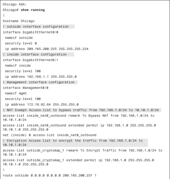
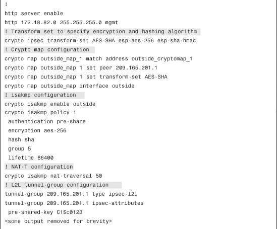
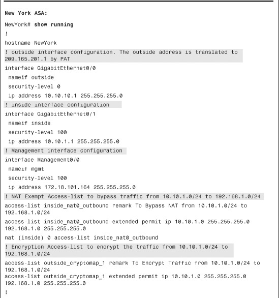
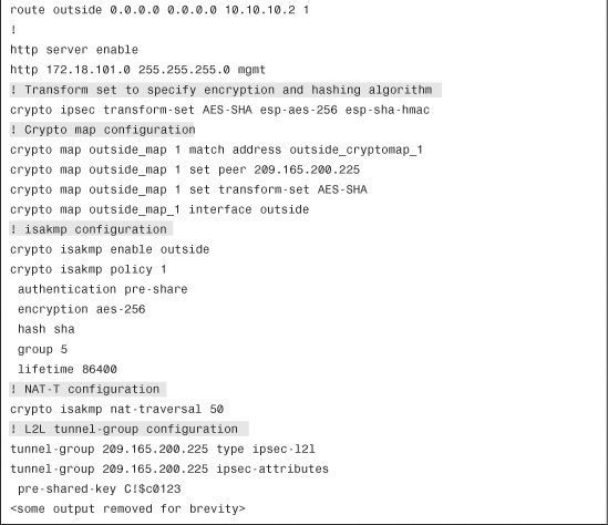
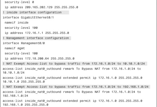
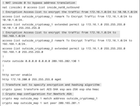
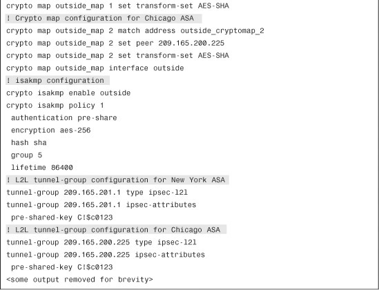
Example 16-25 shows the relevant configuration to achieve the goals listed earlier.
Example 16-25 ASA’s Relevant Configuration for Site-to-Site IPSec Tunnel
Fully Meshed Topology with RRI
SecureMe is planning to add a new site, London, into its existing network. Figure 16-19 shows the new network topology. SecureMe wants to have a fully meshed topology so that each site will have two IPSec tunnels going to the respective IPSec peers. It also wants to use RRI to distribute remote network information into the local network of Chicago, using OSPF.
Figure 16-19 SecureMe Network Using RRI in a Fully Meshed VPN
Configuration Steps Through ASDM
The relevant configuration through ASDM is discussed in the following steps. These configuration steps assume that you have IP connectivity from the ASDM client to the management IP address of the security appliances. The management IP address of the Chicago ASA is 172.18.82.64, the IP address of the New York ASA is 172.18.101.164, and the IP address of the London ASA is 172.18.200.64. Because all three devices need to have identical encryption and hashing policies, the following configurations steps are common across all devices.
Step 1. To enable IKE processing on the outside interface, navigate to Configuration > Site-to-Site VPN > Connection Profile and select the Allow Access option under the Outside access interface.
Step 2. Create an IKE Phase 1 policy by navigating to Configuration > Site-to-Site VPN > Advanced > IKE Policies > Add and specifying the following attributes:
• Priority: 1
• Authentication: pre-share
• Encryption: AES-256
• D-H Group: 5
• Hashing: SHA
• Lifetime: 86,400 seconds. Click OK when you are finished.
Step 3. Create an IPSec transform set by navigating to Configuration > Site-to-Site VPN > Advanced > IPSec Transform Sets > Add and specifying the following attributes:
• Set Name: AES-SHA
• Mode: Tunnel
• ESP Encryption: AES-256
• ESP Authentication: SHA. Click OK when you are finished.
Step 4. Make sure that the Enable Inbound IPSec Sessions to Bypass Interface Access Lists. Group Policy and Per-User Authorization Access Lists Still Apply to the Traffic option is enabled under Configuration > Site-to-Site VPN > Advanced > System Options. It is required to bypass traffic filtering of the encrypted traffic through the interface ACL checks.
Configuration of Chicago ASA
Step 1. Define a Tunnel Group for New York ASA by navigating to Configuration > Site-to-Site VPN > Advanced > Tunnel Group > Add and specifying the following attributes:
• Name: 209.165.201.1
• Preshared Key: C1$c0123
• Make sure that the IPSec Protocol check box is enabled, leave all other options to their default values, and click OK when you are finished.
Step 3. Define a Tunnel Group for London ASA by navigating to Configuration > Site-to-Site VPN > Advanced > Tunnel Group > Add and specifying the following attributes:
• Name: 209.165.202.129
• Preshared Key: C1$c0123
• Make sure that the IPSec Protocol check box is enabled, leave all other options to their default values, and click OK when you are finished.
Step 4. Next, add a crypto map for New York ASA. Navigate to Configuration > Site-to-Site VPN > Advanced > Crypto Maps > Add, click the Tunnel Policy (Crypto Map)- Basic tab, and specify the following attributes:
• Interface: outside
• Policy Type: Static
• Priority: 1
• Transform Set to be Added: AES-SHA and click Add>>.
• Connection Type: bidirectional
• IP Address of Peer to be Added: 209.165.201.1 and click Add>>.
Step 5. To configure RRI, click the Tunnel Policy (Crypto Map)-Advanced tab and select Enable Reverse Route Injection.
Step 6. To specify the interesting traffic for encryption, click the Traffic Selection tab of the crypto map properties and define the following attributes:
• Action: Protect
• Source: 192.168.1.0/24
• Destination: 10.10.1.0/24
• Service: IP
• Description: To Encrypt Traffic from 192.168.1.0/24 to 10.10.1.0/24. Click OK when you are finished.
Step 7. Next, Add a crypto map for London ASA. Navigate to Configuration > Site-to-Site VPN > Advanced > Crypto Maps > Add, click the Tunnel Policy (Crypto Map)- Basic tab, and specify the following attributes:
• Interface: outside
• Policy Type: Static
• Priority: 2
• Transform Set to be Added: AES-SHA and click Add>>.
• Connection Type: bidirectional
• IP Address of Peer to be Added: 209.165.202.129 and click Add>>.
Step 8. To configure RRI, click the Tunnel Policy (Crypto Map)-Advanced tab and select Enable Reverse Route Injection.
Step 9. To specify the interesting traffic for encryption, click the Traffic Selection tab of the crypto map properties and define the following attributes:
• Action: Protect
• Source: 192.168.1.0/24
• Destination: 172.16.1.0/24
• Service: IP
• Description: To Encrypt Traffic from 192.168.1.0/24 to 172.16.1.0/24. Click OK when you are finished.
Step 10. If NAT-Control is enabled, you must bypass address translation for the encrypted traffic. Navigate to Configuration > Firewall > NAT Rules > Add > Add NAT Exempt Rule and define the following attributes for traffic going to New York ASA:
• Action: Exempt
• Interface: inside
• Source: 192.168.1.0/24
• Destination: 10.10.1.0/24
• NAT Exempt Direction: NAT Exempt outbound traffic from interface ‘Inside’ to lower security interfaces (default).
• Description: To Bypass NAT from 192.168.1.0/24 to 10.10.1.0/24. Click OK when you are finished.
Step 11. If NAT-Control is enabled, navigate to Configuration > Firewall > NAT Rules > Add > Add NAT Exempt Rule and define the following attributes for traffic going to London ASA:
• Action: Exempt
• Interface: inside
• Source: 192.168.1.0/24
• Destination: 172.16.1.0/24
• NAT Exempt Direction: NAT Exempt outbound traffic from interface ‘Inside’ to lower security interfaces (default).
• Description: To Bypass NAT from 192.168.1.0/24 to 172.16.1.0/24. Click OK when you are finished.
Step 12. Advertise the static route to the OSPF peers by browsing to Configuration > Device Setup > Routing > OSPF > Redistribution > Add, selecting the OSPF process you are using, choosing Static under the Protocol option, and then selecting the Use Subnets option.
Configuration of New York ASA
Step 1. Define a Tunnel Group for Chicago ASA by navigating to Configuration > Site-to-Site VPN > Advanced > Tunnel Group > Add and specifying the following attributes:
• Name: 209.165.200.225
• Preshared Key: C1$c0123
• Make sure that the IPSec Protocol check box is enabled, leave all other options to their default values, and click OK when you are finished.
Step 2. Define a Tunnel Group for London ASA by navigating to Configuration > Site-to-Site VPN > Advanced > Tunnel Group > Add and specifying the following attributes:
• Name: 209.165.202.129
• Preshared Key: C1$c0123
• Make sure that IPSec Protocol option is enabled and leave all other options to their default values and click OK when you are finished.
Step 3. Next, add a crypto map for Chicago ASA. Navigate to Configuration > Site-to-Site VPN > Advanced > Crypto Maps > Add, click the Tunnel Policy (Crypto Map)- Basic tab, and specify the following attributes:
• Interface: outside
• Policy Type: Static
• Priority: 1
• Transform Set to be Added: AES-SHA and click Add>>
• Connection Type: bidirectional
• IP Address of Peer to be Added: 209.165.200.225 and click Add>>
Step 4. To specify the interesting traffic for encryption, click the Traffic Selection tab of the crypto map properties and define the following attributes:
• Action: Protect
• Source: 10.10.1.0/24
• Destination: 192.168.1.0/24
• Service: IP
• Description: To Encrypt Traffic from 10.10.1.0/24 to 192.168.1.0/24. Click OK when you are finished.
Step 5. Next, add a crypto map for London ASA. Navigate to Configuration > Site-to-Site VPN > Advanced > Crypto Maps > Add, click the Tunnel Policy (Crypto Map)- Basic tab, and specify the following attributes:
• Interface: outside
• Policy Type: Static
• Priority: 2
• Transform Set to be Added: AES-SHA and click Add>>
• Connection Type: bidirectional
• IP Address of Peer to be Added: 209.165.202.129 and click Add>>
Step 6. To specify the interesting traffic for encryption, click the Traffic Selection tab of the crypto map properties and define the following attributes:
• Action: Protect
• Source: 10.10.1.0/24
• Destination: 172.16.1.0/24
• Service: IP
• Description: To Encrypt Traffic from 10.10.1.0/24 to 172.16.1.0/24. Click OK when you are finished.
Step 7. If NAT-Control is enabled, you must bypass address translation for the encrypted traffic. Navigate to Configuration > Firewall > NAT Rules > Add > Add NAT Exempt Rule and define the following attributes for traffic going to Chicago ASA:
• Action: Exempt
• Interface: inside
• Source: 10.10.1.0/24
• Destination: 192.168.1.0/24
• NAT Exempt Direction: NAT Exempt outbound traffic from interface ‘Inside’ to lower security interfaces (default)
• Description: To Bypass NAT from 10.10.1.0/24 to 192.168.1.0/24. Click OK when you are finished.
Step 8. If NAT-Control is enabled, navigate to Configuration > Firewall > NAT Rules > Add > Add NAT Exempt Rule and define the following attributes for traffic going to London ASA:
• Action: Exempt
• Interface: inside
• Source: 10.10.1.0/24
• Destination: 172.16.1.0/24
• NAT Exempt Direction: NAT Exempt outbound traffic from interface ‘Inside’ to lower security interfaces (default)
• Description: To Bypass NAT from 192.168.1.0/24 to 172.16.1.0/24. Click OK when you are finished.
Configuration of London ASA
Step 1. Define a Tunnel Group for New York ASA by navigating to Configuration > Site-to-Site VPN > Advanced > Tunnel Group > Add and specifying the following attributes:
• Name: 209.165.201.1
• Preshared Key: C1$c0123
• Make sure that the IPSec Protocol checkbox is enabled and leave all other options to their default values and click OK when you are finished.
Step 2. Define a Tunnel Group for Chicago ASA by navigating to Configuration > Site-to-Site VPN > Advanced > Tunnel Group > Add and specifying the following attributes:
• Name: 209.165.200.225
• Preshared Key: C1$c0123
• Make sure that the IPSec Protocol checkbox is enabled and leave all other options to their default values and click OK when you are finished.
Step 3. Next, add a crypto map for New York ASA. Navigate to Configuration > Site-to-Site VPN > Advanced > Crypto Maps > Add, click the Tunnel Policy (Crypto Map)- Basic tab, and specify the following attributes:
• Interface: outside
• Policy Type: Static
• Priority: 1
• Transform Set to be Added: AES-SHA and click Add>>
• Connection Type: bidirectional
• IP Address of Peer to be Added: 209.165.201.1 and click Add>>
Step 4. To specify the interesting traffic for encryption, click the Traffic Selection tab of the crypto map properties and define the following attributes:
• Action: Protect
• Source: 172.16.1.0/24
• Destination: 10.10.1.0/24
• Service: IP
• Description: To Encrypt Traffic from 172.16.1.0/24 to 10.10.1.0/24. Click OK when you are finished.
Step 5. Next, add a crypto map for Chicago ASA. Navigate to Configuration > Site-to-Site VPN > Advanced > Crypto Maps > Add, click the Tunnel Policy (Crypto Map)- Basic tab, and specify the following attributes:
• Interface: outside
• Policy Type: Static
• Priority: 2
• Transform Set to be Added: AES-SHA and click Add>>
• Connection Type: bidirectional
• IP Address of Peer to be Added: 209.165.200.225 and click Add>>
Step 6. To specify the interesting traffic for encryption, click the Traffic Selection tab of the crypto map properties and define the following attributes:
• Action: Protect
• Source: 172.16.1.0/24
• Destination: 192.168.1.0/24
• Service: IP
• Description: To Encrypt Traffic from 172.16.1.0/24 to 192.168.1.0/24. Click OK when you are finished.
Step 7. If NAT-Control is enabled, you must bypass address translation for the encrypted traffic. Navigate to Configuration > Firewall > NAT Rules > Add > Add NAT Exempt Rule and define the following attributes for traffic going to New York ASA:
• Action: Exempt
• Interface: inside
• Source: 172.16.1.0/24
• Destination: 10.10.1.0/24
• NAT Exempt Direction: NAT Exempt outbound traffic from interface ‘Inside’ to lower security interfaces (default)
• Description: To Bypass NAT from 172.16.1.0/24 to 10.10.1.0/24. Click OK when you are finished.
Step 8. If NAT-Control is enabled, navigate to Configuration > Firewall > NAT Rules > Add > Add NAT Exempt Rule and define the following attributes for traffic going to Chicago ASA:
• Action: Exempt
• Interface: inside
• Destination: 192.168.1.0/24
• NAT Exempt Direction: NAT Exempt outbound traffic from interface ‘Inside’ to lower security interfaces (default)
• Description: To Bypass NAT from 172.16.1.0/24 to 192.168.1.0/24. Click OK when you are finished.
Configuration Steps Through CLI
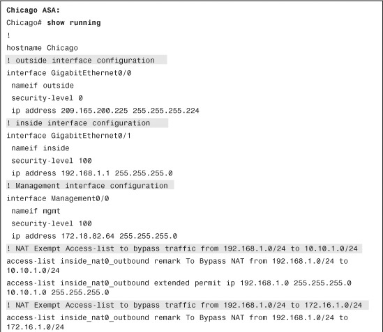
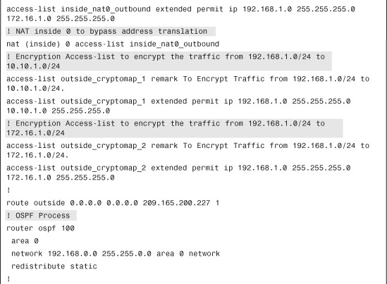
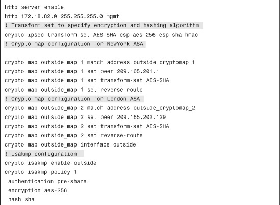
Example 16-26 shows the relevant configuration of all the Cisco ASA devices set up in a fully meshed IPSec network. There are two crypto map instances—one for each peer configured on the security appliances.
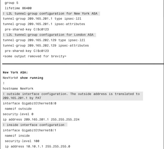
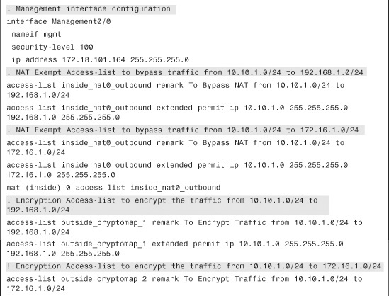
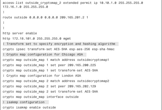
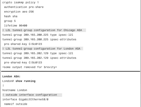
Example 16-26 Full Configuration of the Chicago, London, and Paris ASAs
Monitoring and Troubleshooting Site-to-Site IPSec VPNs
Cisco ASA comes with many show commands to check the health and status of the IPSec tunnels. For troubleshooting purposes, Cisco ASA also provides a rich set of debug commands to isolate the IPSec-related issues.
Monitoring Site-to-Site VPNs
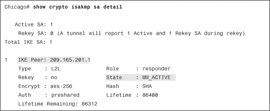
To check the status of the IPSec tunnels, start by looking at Phase 1 SA state. Type show crypto isakmp sa detail, as demonstrated in Example 16-27. If the ISAKMP negotiations are successful, you should see the state as MM_ACTIVE. The example also displays the type of the IPSec tunnel and the negotiated Phase 1 policy.
Example 16-27 Output of show crypto isakmp sa detail
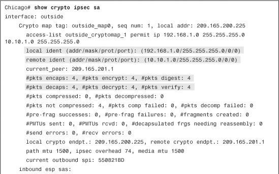
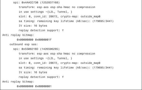
You can also check the status of the IPSec SA by using the show crypto ipsec sa command, as shown in Example 16-28. It displays the negotiated proxy identities (networks to be encrypted), along with the actual number of packets encrypted and decrypted by the IPSec engine.
Example 16-28 Output of show crypto ipsec sa
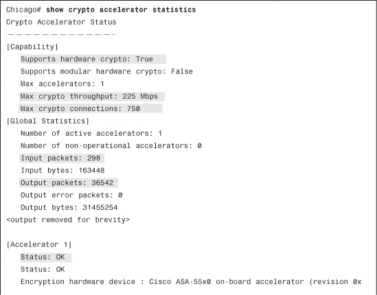
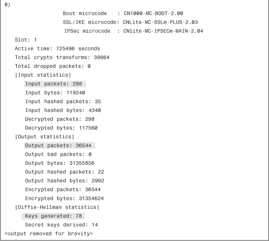
All Cisco ASAs have an encryption accelerator installed. If you want to look at the counter information to monitor how many packets have gone through the card, you can type the show crypto accelerator statistics command, as demonstrated in Example 16-29.
Example 16-29 Output of show crypto accelerator statistics
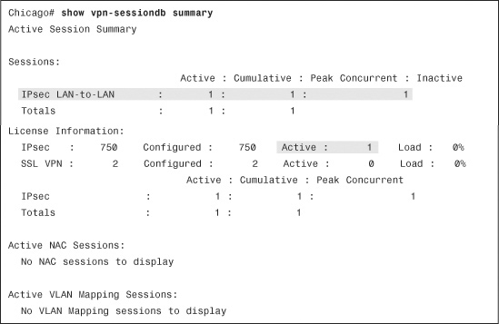
To monitor the IPSec sessions through ASDM, navigate to Monitoring > VPN > VPN Statistics > Sessions and check how many active IPSec tunnels are established on the security appliance. The security appliance shows you all the active VPN sessions, including the remote-access connections. With the CLI, you can find similar information by using the show vpn-sessiondb summary command, as shown in Example 16-30.
Example 16-30 show vpn-sessiondb summary Command Output
Troubleshooting Site-to-Site VPNs
If the IPSec tunnel is not working, make sure that you have the proper debug turned on. The two most important debug commands to look at are the following:
debug crypto isakmp [debug level 1-255]
and
debug crypto ipsec [debug level 1-255]
By default, the debug level is set to 1. You can increase the debug level up to 255 to get detailed logs. However, in most cases, setting the logging level to 127 gives enough information to determine the root cause of an issue.
Refer to Figure 16-1 for an example of a site-to-site tunnel between the ASAs in Chicago and New York. The ISAKMP and IPSec negotiations are discussed on the security appliance in Chicago. The following debug commands are enabled on the security appliance:
Chicago# debug crypto isakmp 127
Chicago# debug crypto ipsec 127
Tip
If you have hundreds of IPSec sessions established to a security appliance, enabling the crypto isakmp and crypto ipsec debugs can generate a lot of output.
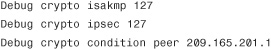
In version 8.0 or higher, the crypto conditional debug feature was introduced, which enables a user to debug an IPSec tunnel based on predefined conditions such as the peer’s IP address, SPI values, or even the connection ID. For example, if you want to look at the crypto isakmp and crypto ipsec debugs for peer 209.165.201.1, enable the following commands:
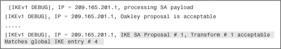
As mentioned in Chapter 1, the tunnel negotiations begin with an exchange of ISAKMP proposals. If the proposal is acceptable, the ASA displays the IKE SA Proposal Transform Acceptable message, as shown in Example 16-31.
Example 16-31 Debugs to Show ISAKMP Proposal Is Acceptable
Note
The VPN debug messages on the security appliance are very similar to the log messages generated on the VPN 3000 Series Concentrators.
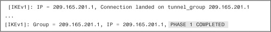
During the ISAKMP SA negotiations, the security appliance matches the IP address of the VPN peer with the tunnel group. If it finds a match, it displays a “Connection landed on tunnel group” message, as shown in Example 16-32, and continues with the rest of the negotiations (shown as ...). The Cisco ASA displays a Phase 1 Completed message when the ISAKMP SA is successfully negotiated.
Example 16-32 Debugs to Show Phase 1 Negotiations Are Completed
After completing Phase 1 negotiations, the security appliance maps the remote VPN peer to a static crypto map sequence number and checks the IPSec Phase 2 proposal sent by the remote VPN peers. If the received proxy identities and the IPSec Phase 2 proposals match on the security appliance, it displays an IPSec SA Proposal Transform Acceptable message, as demonstrated in Example 16-33.
Example 16-33 Debugs to Show Proxy Identities and Phase 2 Proposals Are Accepted
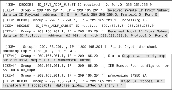
After accepting the transform set, both VPN devices agree on the inbound and outbound IPSec SAs, as shown in Example 16-34. After the IPSec SAs have been created, both VPN devices should be able to pass bidirectional traffic across the tunnel.
Example 16-34 Debugs Showing IPSec SAs Are Activated
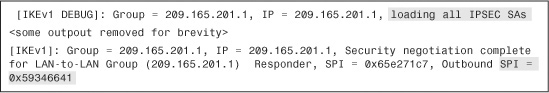
The following four scenarios discuss how to troubleshoot the common issues related to IPSec tunnels. The debug messages are shown if debug crypto isakmp 127 is enabled on the security appliance.
ISAKMP Proposal Unacceptable
In this scenario, if the ISAKMP proposals are mismatched between the two VPN devices, the Cisco ASA appliance displays an All SA Proposals Found Unacceptable message after processing the first main mode packet, as shown in Example 16-35.
Example 16-35 Debugs to Show Mismatched ISAKMP Policies
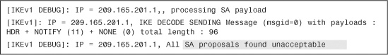
Mismatched Preshared Keys
If the preshared key is mismatched between the VPN devices, the Cisco ASA appliance displays an Error, Had Problems Decrypting Packet, Probably Due to Mismatched Pre-Shared Key message after processing the fourth main mode packet. This is shown in Example 16-36.
Example 16-36 Debugs to Show Mismatched Preshared Keys
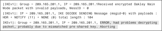
Incompatible IPSec Transform Set
The security appliance displays an All IPSec SA Proposals Found Unacceptable message if the IPSec transform set is mismatched between the VPN devices. In this case, the Phase 1 SA gets established and the VPN devices fail to negotiate the IPSec SA. The Cisco ASA checks the validity of the crypto map before rejecting the IPSec SA, as shown in Example 16-37.
Example 16-37 Debugs When Incompatible IPSec Transform Set Is Used
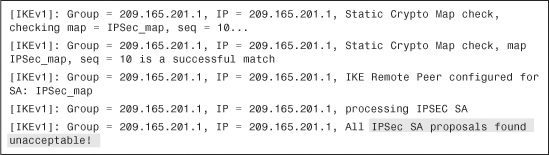
Mismatched Proxy Identities
If the encryption ACL on the security appliance does not match the encryption ACL offered by the other end of the VPN tunnel, the Cisco ASA rejects the IPSec SA and displays a No Matching crypto map Entry error with the associated local and remote subnets that the remote VPN device offered. In Example 16-38, the VPN peer 209.165.201.1 wants to negotiate IPSec SAs between 10.10.1.0 and 192.168.2.0, which the security appliance rejects because the received identities do not match the configured crypto ACL.
Example 16-38 Debugs to Show Mismatched Proxy Identities

ISAKMP Captures
If you are troubleshooting an IPSec issues on the security appliance and prefer to see the detailed debug messages for the IPSec tunnel negotiations, you can enable the ISAKMP capture on the interface that terminates the VPN tunnel. After the captures are enabled, the security appliance captures the interesting packets and stores them in the buffer. You can view the captures packets by using the show capture command. In Example 16-39, an ISAKMP capture, called IPSecCapture, is enabled on the outside interface. After enabling the capture, try to establish the VPN tunnel by sending interesting traffic over the tunnel. Last, issue the show capture IPSecCapture decode command to view the log messages.
Example 16-39 Enable ISAKMP Captures
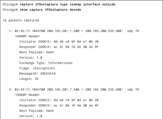
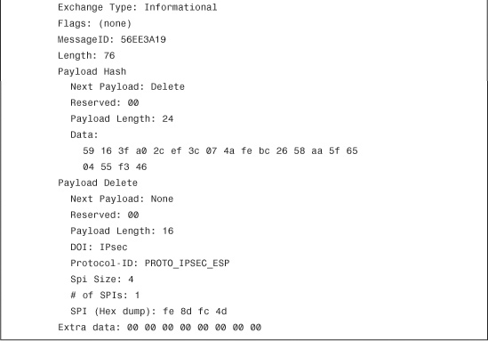
Summary
Every day, more and more organizations are deploying IPSec site-to-site tunnels to cut costs on traditional WAN links. It is the responsibility of the security professional to design and implement an IPSec solution that will fit the needs of an organization. If the other end of the IPSec VPN tunnel is managed by a different security professional, make sure that you consult with him before configuring the ISAKMP and IPSec attributes in the ASA. This chapter discussed the configuration necessary to implement the site-to-site tunnels and discussed two deployment scenarios. If you implement the solution, and the IPSec tunnel is not working as expected, use the appropriate show commands and monitor the status of the SAs. You can also turn on the ISAKMP and IPSec debug commands to help troubleshoot the issue.