Chapter 11. Quality of Service
In a standard IP network, all packets are processed identically, based on best effort. The network devices usually ignore the importance or criticality of the data that is passing through the network. This creates problems in deployments where time-sensitive traffic, such as voice and video packets, is delayed or dropped because the network devices do not prioritize it over other traffic. The feature of prioritizing some traffic over other traffic is known as quality of service (QoS).
Imagine a long-distance phone call that involved a satellite connection. If the conversation is interrupted with brief, but perceptible, gaps at odd intervals, you cannot tolerate long latency times. Using QoS, you can prioritize the VoIP traffic to prevent against bandwidth hogging and protect time-sensitive traffic.
QoS is useful in almost any network deployment, including the following:
• You run voice, video, and data traffic on the same network. Because voice and video streams are time sensitive and do not tolerate network delays, QoS policies must be implemented to ensure traffic prioritization.
• You run data applications such as time-sensitive databases that require traffic prioritization if there is congestion on the network.
• You want to prioritize management traffic, such as Telnet or SSH, so that you do not lose access to the network devices if there is an outbreak of a new virus in the local network.
• You are a service provider and want to offer different classes of service (CoS) to your customers, based on their needs.
• You have virtual private networks (VPNs) deployed and you want to prioritize or rate-limit traffic going over the VPN tunnel.
Note
QoS is useful in policing, shaping, and prioritizing packets only when there is congestion in the network. For end-to-end QoS, all network devices along the path should be QoS-capable.
Many different types of QoS mechanisms are available in the Cisco devices, such as the following:
• Traffic marking
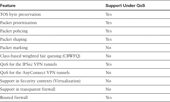
Table 11-1 displays QoS compatibility on the security appliance when other features, such as a transparent firewall, are implemented.
Table 11-1 Support of QoS with Other Features
QoS Types
Cisco ASA supports three types of QoS:
You configure all these methods by using the robust Modular Policy Framework (MPF), discussed briefly in Chapter 7, “Application Inspection.”
Traffic Prioritization
Traffic prioritization, also known as class of service (CoS) or low-latency queue (LLQ), is used to give important network traffic precedence over normal or unimportant network traffic. It assigns to traffic different priority levels or classes, such as high, medium, and low. The lower the packet’s importance, the lower its priority, and thus the greater its chances of getting dropped in case of network congestion.
In the current implementation of Cisco ASA, two classes of traffic prioritization are supported: priority QoS and nonpriority QoS. With priority QoS packets are prioritized over regular traffic, whereas with nonpriority QoS packets are processed by the rate limiter, discussed in the next section.
When traffic is classified as priority, it gets express-forwarded without passing through the rate limiter. The traffic is then flagged to take the priority queue at the egress interface level.
To ensure priority forwarding of traffic at the interface, the security appliance looks at the flag for the priority queue and sends the packet for immediate transmission unless the transmit ring is congested. In that case, traffic is queued to the high-priority queue. As soon as the transmit ring has room available, the security appliance services the priority queue and transmits the packet.
Note
Traffic prioritization and traffic policing are the two mutually exclusive methods for setting up QoS. You cannot prioritize some traffic and simultaneously police it in same class map configuration, discussed later in this chapter under “Configuring Quality of Service.” If you try to configure traffic policing while priority is configured, you receive the following error message:
ERROR: Must deconfigure priority in this class before issuing this command
Traffic Policing
Traffic policing, also known as traffic rate-limiting, allows you to control the maximum rate of traffic eligible to pass through an interface. Traffic that falls within the configured parameters is allowed to pass, whereas traffic that exceeds the limit is dropped.
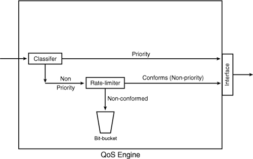
In Cisco ASA, if traffic is not classified as “priority,” as discussed in the preceding “Traffic Prioritization” section, it is processed through the rate limiter. The security appliance tags the packet for rate-limiting and sends the packet to the QoS engine for processing. The packet passes through the rate limiter, which determines whether the packet conforms to the configured rate. If it does not, then the packet can be forwarded for additional processing or can be dropped based on the policies. If it conforms to the configured rate, the packet is flagged to take the nonpriority queue. Figure 11-1 illustrates how a packet is processed in the security appliance when it passes through the QoS engine.
Figure 11-1 Packet Flow Through the QoS Engine
When traffic leaves the QoS engine, it is forwarded to the egress interface for physical transmission. The security appliance implements another level of QoS processing at the interface to guarantee traffic with a non-priority flag gets proper handling. Packet processing at the interface depends on the depth of the queue and the conditions of the transmit ring. The transmit ring is the buffer space used by the security appliance to hold packets before transmitting them at the driver level. If the ring is congested, the packet is queued. If the transmit ring has room, the non-prioritized packet is sent immediately after ensuring that the priority queue is empty. If the priority queue has traffic to send, the transmit ring services it first.
With QoS rate limiting, the security appliance implements a tail drop mechanism when a packet does not conform to the configured profile. The tail drop mechanism drops the packets at the end of the queue if the queue is already full. Cisco ASA logs this event through syslog locally in the buffer or to an external server.
Traffic Shaping
Traffic shaping is a mechanism that enables you to control the rate of traffic through the security appliance. This is extremely useful in scenarios where you have congested WAN links and you are sending more traffic through the security appliance than your WAN link can support. For example, if you have a 5510 with a 100 Mbps interface with an upstream Internet gateway with a 10 Mbps uplink, then you can define traffic shaping policies on the security appliance so that the excessive packets can be queued up for transmission over time at the configured rate. If the queue is full, packets are tail-dropped.
Traffic shaping is implemented when a packet is about to be transmitted on an outbound interface. This includes shaping both through-the-box and from-the-box traffic. With traffic shaping, you cannot
• Shape traffic in any traffic selection class, other than the default class. This is discussed later in the chapter under the “Configuring Quality of Service” section.
• Shape traffic on multiple VLAN interfaces defined under a physical interface. Traffic shaping is allowed only on the physical interface or, in the case of a Cisco ASA 5505, on a VLAN interface.
• Shape traffic on a 5580 security appliance.
In the current implementation, Cisco ASA enables you to configure limited hierarchical QoS policies. This allows you to shape traffic on an interface and within the shaped traffic, you can prioritize specific traffic such as VoIP. The hierarchical QoS policy support allows you to shape traffic only at the top level and then provide priority queuing at the next level. With this implementation, you cannot
• Prioritize traffic and then shape it.
• Police traffic and then shape it.
• Shape traffic and then police it.
Using the hierarchical QoS policy, the prioritized packets are always queued at the head of the shaped traffic and therefore prioritized packets are transmitted ahead of any other traffic. Similarly, the prioritized packets are never dropped from the shaped queue unless the sustained rate of the prioritized traffic exceeds the shaped traffic rate.
Additionally, Cisco ASA does not allow you to shape specific traffic flows. For example, you cannot shape the outbound SSH traffic on the outside interface to 1 Mbps.
Note
Certain critical keep-alive packets such as EIGRP Hello packets are never dropped even if they are not prioritized in the shaped traffic.
QoS Architecture
The following sections examine packet flow sequence and packet classification in the security appliance when QoS is applied on an interface.
Packet Flow Sequence
When a packet passes through a security appliance configured for QoS, the following sequence of events occurs, as illustrated in Figure 11-2:
Figure 11-2 Packet Flow Through the Security Appliance
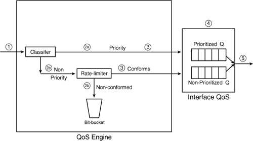
Step 1. The packet arrives at the ingress interface. If it is the first packet of the flow, the security appliance attempts to route the packet out to the proper interface and creates a flow for the subsequent packets. The flow contains the rules and actions associated with the packets.
Step 2. Based on the QoS rules, the security appliance takes one of the following actions:
• If the packet matches the priority queue, it is directed to the prioritized queue for express handling. For the priority queue, there is no rate limiting on the packets.
• If rate limiting is configured on the security appliance, the packet is checked to see whether a flow for QoS is already established. If there is none, a flow is created based on the source and destination IP address, source and destination ports, IP protocol, and the interfaces forwarding the packets. The security appliance checks that it conforms to the configured rate-limiting parameters. If traffic matches a rate-limiting policy but exceeds the threshold, the security appliance drops the packet. If traffic does not match a rate-limiting policy and a default class is defined with traffic shaping, the security appliance shapes traffic based on the configured parameters and buffer burst traffic in the queue.
Step 3. At this point, the QoS flow is up and the packet is forwarded to the egress interface for physical transmission.
Step 4. The egress interface has two allocated queues for QoS. One is used for the prioritized traffic and the other is used for the non-prioritized traffic. If traffic is rate-limited and there are packets to be sent in the prioritized queue, the security appliance services the prioritized queue first and then processes the rate-limited queue.
Step 5. The security appliance transmits the packet over the physical interface.
Packet Classification
Packet classification is a way to identify packets on which QoS policies need to be applied. This can range from simple functions such as IP precedence and DSCP fields to complicated methods such as complex access lists. The following subsections discuss the supported packet-classification methods.
IP Precedence Field
IP packets contain a type of service (TOS) byte, which is used to indicate the priority in which the packets should be processed. In the TOS byte, the leftmost three bits set the IP precedence, as shown in Figure 11-3. The network devices use the next four bits, known as the TOS bits, to determine how a packet should be handled by looking at delay (D), throughput (T), reliability (R), and cost (C). However, these bits are not currently used in the IP network infrastructures. The last bit in the TOS byte is typically referred as MBZ (abbreviation for “must be zero”). This bit is not used, either.
Figure 11-3 TOS Byte Displaying IP Precedence Bits
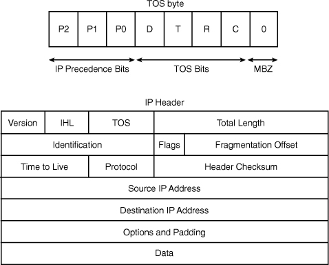
Table 11-2 lists all the IP precedence bits along with their IP precedence names as defined in RFC 791.
Table 11-2 IP Precedence Bits and IP Precedence Names

IP DSCP Field
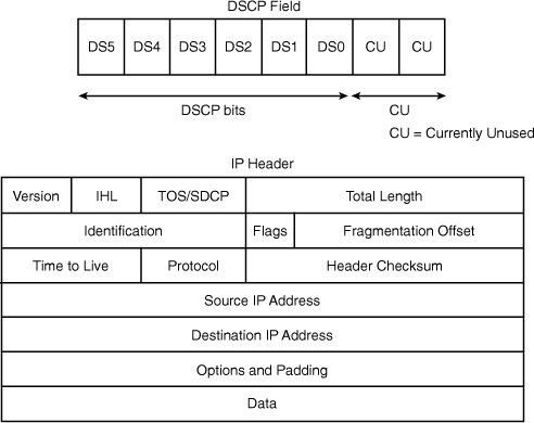
Differentiated Services Code Point (DSCP) is intended to replace the definitions of the IP TOS byte. DSCP field takes the same space within the IP header as the IP TOS byte. It uses the six most significant bits for packet classification. The two least significant bits are currently unused, as shown in Figure 11-4. By using the six bits in DSCP, you can classify up to 64 streams of packets.
DSCP provides backward compatibility to IP precedence. Table 11-3 lists the IP precedence values with the corresponding DSCP values.
Table 11-3 Correlation of IP Precedence Bits to DSCP Bits
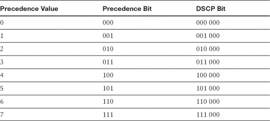
As shown in Table 11-3, DSCP offers fine granularity to packet identification by using the additional three bits. The Internet Engineering Task Force (IETF) has divided the DSCP bits into four service concepts:
• Default DCSP, defined as 000 000, offers best-effort packet switching through the network devices.
• Class selector provides backward-compatibility bits, shown in Table 11-3. All the DSCP bits shown in the table belong to this service.
• Expedited Forwarding (EF) per-hop behavior (PHB), with the DSCP bit of 101 110, defines the premium service for the IP packets.
• Assured Forwarding (AF) PHB, with four different classes and three different class levels, defines a total of 12 code points for packet classification.
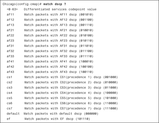
Example 11-1 lists the well known DSCP bits supported by Cisco ASA.
Example 11-1 Available DSCP Options in Class Maps
Note
The QoS implementation in Cisco ASA observes and honors the DSCP and IP precedence bits in the packet. For the IPSec VPN tunnels, the security appliance preserves the TOS byte from the inner header to the outer header. By doing so, the security appliance and the devices along the VPN tunnel can correctly prioritize traffic.
IP Access Control List
Access control lists (ACLs) are the most commonly used form of packet classification. They can identify traffic based on many Layer 3 as well as Layer 4 headers of the packet. Please consult Chapter 4, “Controlling Network Access,” for more information about ACL.
IP Flow
Classification based on IP flow is usually based on information found in the following five tuples:
• Destination IP address
• Source IP address
• Destination port
• Source port
• IP protocol field
In Cisco ASA, flow-based classification is done based on the destination IP address. That means that if the traffic is destined to an IP address, an IP flow is created and the appropriate policies are applied to it.
VPN Tunnel Group
Cisco ASA can also classify packets destined to an IPSec tunnel. When a packet is received by the security appliance and matches a particular tunnel group (whether site-to-site or remote-access), the security appliance applies the configured QoS policies before transmitting the packet.
Note
The security appliance allows only one match command in the class map. However, you can have two match commands when setting up QoS for the VPN tunnels. Use the match tunnel-group <tunnel-group-name> command in the class map first before specifying a second qualifying match statement in the class map. Currently, match flow ip destination-address is the only supported second match command.
QoS and VPN Tunnels
Cisco ASA supports full QoS implementation on both the site-to-site and remote-access VPN tunnels. For the best-effort method, the site-to-site QoS implementation rate-limits traffic for the entire tunnel. This means that all hosts within the tunnel share the same bandwidth. However, for the remote-access VPN tunnels, the QoS implementation rate-limits traffic per remote-access peer. This means that each VPN tunnel within a remote-access group gets the configured data throughput.
Note
Even though there is a static ACL for each site-to-site tunnel, the QoS rules are not inserted into the database until there is an active VPN tunnel. This ensures that the security appliance does not allocate bandwidth for the IPSec security associations (SAs) that are not being used.
When both QoS and VPN engines are set up on the security appliance, the following events can occur during device configuration:
• New QoS policy is set up for existing tunnels—If a QoS policy is applied to an interface with an active VPN tunnel, the security appliance invokes the IPSec engine to apply the appropriate QoS parameters to the IPSec SAs.
• Tunnel goes down for QoS-enabled group—When a VPN tunnel goes down (whether a user deletes the connection or the administrator clears the established SA), the security appliance invokes the QoS process to delete the appropriate QoS parameters for that particular IPSec SA.
• QoS policy is removed for the group—When the VPN commands are removed from the QoS configuration, the security appliance invokes the QoS engine to clear up relevant parameters. The security appliance also makes sure not to call the QoS engine for the future VPN tunnels.
Configuring Quality of Service
The QoS configuration on Cisco ASA can be achieved in the following two ways:
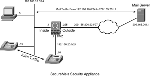
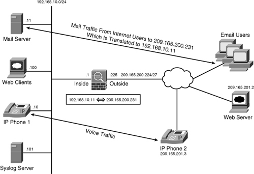
In Figure 11-5, SecureMe, a fictional company, has Cisco ASA set up to classify traffic sourced from the 192.168.10.0/24 subnet and destined to the mail server, 209.165.201.1. The administrator of the security appliance also prefers to identify the Voice over IP (VoIP) traffic passing through the security appliance.
Figure 11-5 Packet Classification in an Appliance
QoS Configuration via ASDM
After you are logged in to the security appliance via ASDM, you must tune the priority queue in case you want to prioritize traffic. After a priority queue is defined, you can create a new QoS policy.
To create a QoS policy, follow the steps described in the following sections.
Step 1: Tune Priority Queue
When the QoS engine has processed the packets, they are queued to the interface for transmission on the wire. The security appliance implements the priority queue at the interface to ensure that prioritized packets are preferred over nonprioritized packets. If the priority queuing is not enabled on an interface, you cannot configure packet prioritization. If you do not want to prioritize traffic, you do not have to configure priority queue.
You can define the transmit ring and the depth of the priority queues to minimize the delay for the high-priority packets. The transmit ring specifies the number of packets allowed into the interface driver’s transmit queue. The depth of the priority queues specifies the maximum number of packets that can be queued up to a priority queue before packets start getting dropped.
The queue’s upper limit and the transmission ring are dynamically determined at run time. The main factor is the amount of memory available on the device to support the queues. When both queues are full and the QoS engine is forwarding more traffic than the queues can handle, the security appliance simply drops the received data. Moreover, it processes the transmit ring first before servicing the priority queues.
Note
Cisco 5580 security appliances do not support priority queue on the 10-Gigabit Ethernet interfaces.
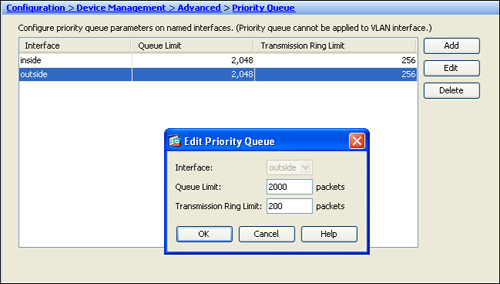
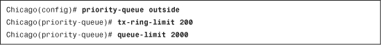
You can tune a priority queue for an interface by navigating to Configuration > Device Management > Advanced > Priority Queue. In Figure 11-6, the administrator of the security appliance has fine-tuned the priority queue parameters on the outside interface. The transmit-ring limit is changed to hold up to 200 packets in the queue, whereas the high- and low-priority queue depth is set up to hold 2000 packets. This allows the priority queue to be processed efficiently with minimum latency caused by the transmit ring.
Figure 11-6 Priority Queue for the Outside Interface
Step 2: Define a Service Policy
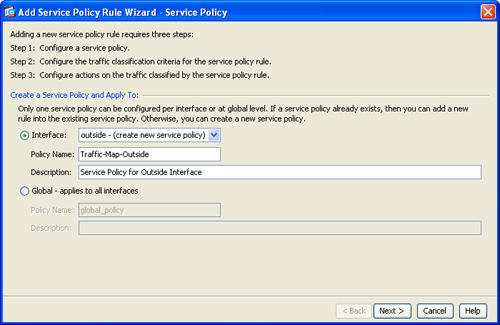
After tuning the priority queue, you can create a new QoS policy by navigating to Configuration > Firewall > Service Policy Rules, selecting the pull-down Add list, and clicking Add Service Policy Rule. ASDM opens up a new window and prompts you to select whether you want to create an interface or a global policy.
• Interface—If you want to create a QoS policy for a specific interface, select the Interface option. Interface policies takes precedence over global policies, as discussed in Chapter 7. An interface specific policy is useful if, for example, you want to prioritize all VPN traffic on the outside interface. In this case, you want to apply the QoS policies on the outside interface. You can define all types of QoS policies (traffic prioritization, traffic shaping, and traffic policing) to an interface-based service policy.
• Global–Applies to All Interfaces—If you would rather apply a QoS policy on all interfaces, select the Global–Applies to All Interfaces option. A global policy is useful if, for example, you want to prioritize all VoIP traffic on all interfaces. In this case, you want to apply the QoS policies globally on the Cisco ASA. You cannot define a traffic-shaping policy to the global policy.
In Figure 11-7, a new service policy, called Traffic-Map-Outside, is applied on the outside interface. A description of Service Policy for Outside Interface is also added to this policy.
Figure 11-7 Defining a New Service Policy
Step 3: Specify a Traffic Selection Criteria
In the next step, you identify packets to which you want to apply the QoS policies. In the security appliance, there are many ways to classify traffic. However, the use of an ACL is the most robust method available for selecting a specific traffic type. You can specify the Layer 3 and Layer 4 information in the packets when ACLs are used. The security appliance can also match based on the DSCP and IP precedence bits in the IP header.
Table 11-4 defines all the methods available for traffic selection criteria.
Table 11-4 Available Traffic Selection Criteria
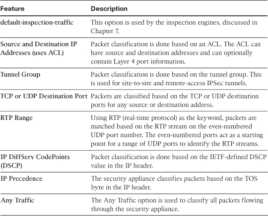
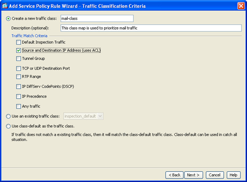
Figure 11-8 shows that a new traffic selection criterion is defined as mail-class. Our goal is to identify the mail server located at 209.165.201.1. To achieve this goal, ACL (Source and Destination IP Addresses) is used to identity interesting traffic for the service policy. When you click Next, the security appliance prompts you to specify the source and destination IP address of the traffic to which you want to apply the QoS policies.
Figure 11-8 Selecting a Traffic Criteria
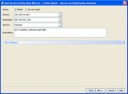
In the next window, specify the IP addresses to be used for traffic classification. In Figure 11-9, the source network is 192.168.10.0/24, whereas the destination is a mail server located at 209.165.201.1. The destination service is tcp/smtp, and a description of ACL to identify outbound mail traffic is also added. Click Next when you are finished.
Figure 11-9 Defining Traffic Criteria
In addition to the traffic selection criteria, the security appliance has a default class that can be used in catch all situations. Any traffic that is not explicitly matched by the selection criteria can be caught by this default class. You can apply appropriate actions (traffic prioritization, shaping, or policing) to the default class. Traffic shaping can be applied only to a default class. To enable the default class for QoS policies, select “Use class-default as the traffic class.”
Step4: Apply an Action Rule
In the final step, the security appliance prompts you to apply a QoS action for your identified traffic. As mentioned earlier in the chapter, you have three options:
Traffic Prioritization
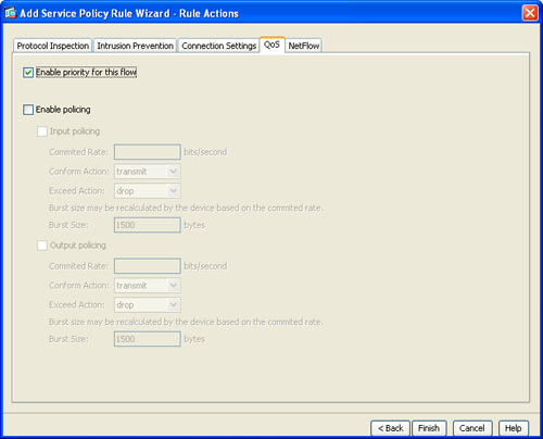
As mentioned earlier in the chapter, you can prioritize specific traffic through the LLQ while all other traffic goes to the best-effort queue on an interface. After you have identified traffic that you want to prioritize, discussed in Step 2, you can click the QoS tab and then select the Enable priority for this flow option, as shown in Figure 11-10.
Figure 11-10 Enabling Traffic Priority
Traffic Policing
If you would rather police some interesting traffic, Cisco ASA allows you to use traffic policing to rate-limit that. If traffic falls in the police rate and burst size, the security appliance transmits traffic. The police rate is the actual rate that can pass through the QoS engine. It ranges from 8000 bps (bits per second) to 2 billion bps.
The burst size is the amount of instantaneous burst that the security appliance can send at any given time without applying the exceed action. The following formula can be used to configure the burst size:
Burst size = (Policing Rate) [ts] 1.5 / 8
For example, if traffic needs to be limited to a police rate of 56,000 bps, the burst size will be 10,500 bytes. The valid range for burst size is from 1000 to 512,000,000 bytes.
Note
The policing rate is in bits per second, whereas the burst size is in bytes.
In Figure 11-11, the security appliance is configured to rate-limit the identified traffic to 56000 bits/second in the outbound direction, with a burst size of 10,500 bytes. If traffic falls within this range, the security appliance transmits it as it conforms to the configured policy. Otherwise, traffic that exceeds these rates is dropped.
Figure 11-11 Enabling Traffic Policing
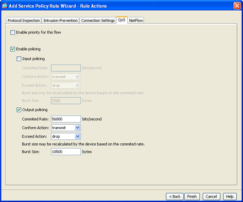
The default conform action is to transmit traffic, whereas the default exceed action is to drop it.
Traffic Shaping
As discussed earlier in the chapter, you can only configure the traffic shaping policies within a default traffic class. The security appliance enables you to specify the average rate of shaped traffic over a period of time. For example, if your WAN link speed is 2 Mbps, you can specify the average rate of shaped traffic to be 2 Mbps also.
The security appliance, optionally, enables you to specify the average size of burst that can be transmitted in a time interval. The following formula can be used to calculate the time interval:
Time interval (t) = (average burst size) / (average rate of shaped traffic)
The effect of the burst size and the time interval can be best explained by an example. If, for example, you want to shape traffic at 2 Mbps on a 100 Mbps interface and specify 500 Kbps as the burst size, the time interval is 250 msecs. What that means is, every 250 msecs the security appliance sends 500 Kbps traffic. Because the outbound interface is a 100 Mbps interface, it can send 500 Kbps traffic in the first 5 msec and then the link is idle for the remaining 245 msecs until the next time interval. If the time interval is too large, delay-sensitive traffic such as voice or video can be severely impacted.
In Figure 11-12, the security appliance is configured to shape traffic at 2 Mbps with an average burst size of 16 Kbps so that the time interval is 8 msecs.
Figure 11-12 Enabling Traffic Shaping
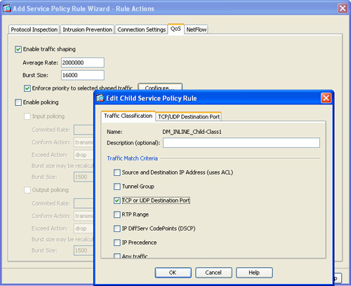
As mentioned earlier in the chapter, the security appliance supports concurrent interface shaping and priority queuing on an interface by using the hierarchical QoS policies. You can shape traffic on an interface and then prioritize specific data packets within the shaped traffic. In Figure 11-12, the security appliance is configured to prioritize some data based TCP and UDP ports within the shaped traffic.
Note
The security appliance does not permit you to prioritize some data within the shaped traffic if you are prioritizing traffic in a different traffic selection class and both of them belong to the same service policy.
QoS Configuration via CLI
Like the QoS configuration via ASDM, the QoS configuration via the CLI can be broken into the following four steps:
Step 1. Tune the priority queue.
Step 3. Configure a policy map.
Step 4. Apply the policy map on the interface.
Step 1: Tune the Priority Queue
Configure the priority queue on an interface by using the priority-queue command, followed by the name of the interface. In Example 11-2, the administrator of the security appliance has fine-tuned the priority queue parameters on the outside interface. The transmit-ring limit is changed to hold up to 200 packets in the queue, whereas the high- and low-priority queue depth is set up to hold 2000 packets. This enables the priority queue to be processed efficiently with minimum latency caused by the transmit ring.
Example 11-2 Configuration of Priority Queue
Note
On Cisco ASA Model 5505, when you configure priority-queue on one interface, it overwrites the same values on all other interfaces as well.
Step 2: Set Up a Class Map
A traffic class identifies packets on which you want to apply the QoS policies. This is similar to the traffic selection criteria you define via ASDM. You create a traffic class by using the class-map command, followed by the name of the class. You do packet classification by using the match statements along with the appropriate option, described earlier in Table 11-4.
Note
You cannot configure multiple match statements under one class map, with one exception: One additional match statement is allowed when you have match tunnel-group or default-inspect-traffic commands configured in a class map.
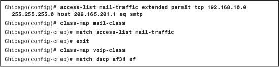
Example 11-3 shows how to configure a class map for identifying mail and VoIP packets. An ACL named mail-traffic is configured to specify the source and destination IP addresses and the TCP destination port 25 (SMTP). This ACL is mapped to a class map called mail-class. One additional class map, voip-class, is set up to identify VoIP packets. VoIP uses DSCP values af31 and ef for voice signaling and RTP streams, respectively.
Example 11-3 Class Maps to Identify Mail and VoIP Traffic
Note
If you configure two classes with overlapping traffic and then apply policies to rate-limit traffic, the security appliance applies the most stringent traffic policy.
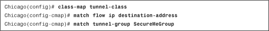
The security appliance can also match traffic destined to go over a tunnel. By using the match tunnel-group command, you can identify packets if they match against a VPN connection. In Example 11-4, the administrator has configured a class map called tunnel-class to identify traffic destined to go over a VPN group called SecureMeGroup. The administrator also uses destination-based IP flow to match traffic.
Note
The use of match flow ip destination-address along with tunnel-group is mandatory if the VPN traffic needs to be rate-limited. You do not need to use match flow ip destination-address if the VPN traffic needs to be prioritized.
Example 11-4 Class Maps to Identify Tunnel Traffic
Note
If you configure two classes with overlapping traffic, and apply priority to one class and rate limiting to the other class, the security appliance matches traffic to the priority queue and does not apply the rate-limited policies.
Step 3: Configure a Policy Map
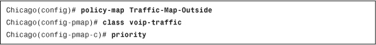
The configured class maps are bound to a policy map that defines the action to be applied on the identified traffic. Apply the priority, rate-limit, or shaping QoS functions under the policy-map sub-configuration mode. Example 11-5 shows a policy map called Traffic-Map-Outside configured to apply actions to the class maps, defined in the previous step. The class map, such as mail-class, voip-class, and/or tunnel-class, is linked to the policy map by the class command.
Example 11-5 Configuration of Policy Maps in the Security Appliance
![]()
After mapping the class and the policy maps, Cisco ASA needs to be configured for an action that can be applied to the identified traffic. In Example 11-6, the security appliance is configured to prioritize VoIP traffic by the priority statement.
Example 11-6 Traffic Prioritization for the VoIP Traffic
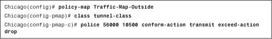
In Example 11-7, the security appliance is configured to rate-limit the tunnel traffic to 56 Kbps, with a burst size of 10,500 bytes. If traffic falls within this range, the security appliance transmits it because it conforms to the configured policy. Otherwise, traffic that exceeds these rates is dropped.
Example 11-7 Rate-Limiting of Tunnel Traffic
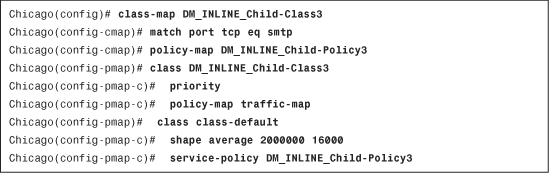
The security appliance also has a default class configured to match all the remaining traffic. This class can be used for shaping traffic at an average rate. In Example 11-8, a default traffic class is configured to shape traffic at 2 Mbps with 16 Kbps as the average burst size. Within this class, another policy-map called DM_INLINE_Child-Policy3 is defined to prioritize SMTP traffic.
Example 11-8 Traffic Shaping and Hierarchical Traffic Priority
Step 4: Apply the Policy Map on the Interface
The next step in completing the QoS configuration is the association of the policy map to an interface. You do so by using the service-policy command along with the policy name and the interface on which the policy needs to be applied. Example 11-9 demonstrates how to apply a policy map called Traffic-Map-Outside to the outside interface.
Example 11-9 Applying QoS on the Outside Interface
![]()
Cisco ASA supports policing, shaping, and prioritizing traffic in the outbound direction. However, traffic policing is also supported in the inbound direction. That means that if the service policy is applied to the outside interface in the inbound direction, then the classified packets can be inspected in the ingress direction.
Note
An interface-based QoS policy takes precedence over a global QoS policy. The global QoS policy is applied to all the interfaces.
QoS Deployment Scenarios
The QoS solution is extremely useful when organizations run into network congestion, or when they want to prioritize some network traffic over other traffic. Although this important feature can be deployed in many ways, this section covers two design scenarios for the ease of understanding:
• QoS for the remote-access VPN tunnels
Note
The design scenarios discussed in this section should be used solely to enforce learning. They should be used for reference purposes only.
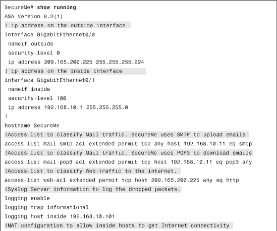
QoS for VoIP Traffic
SecureMe’s information technology (IT) group is responsible for providing network services to its internal users. The IT group hosts an email server and uses Cisco IP Phones for telecommunications. SecureMe management has some specific requirements that the IT group is obliged to meet:
• Internal clients should have full Internet web access. They should get bandwidth based on best effort and should be restricted to 56 Kbps.
• For VoIP calls, there should not be any network-related delays.
• Internet email users should not be allowed to fully utilize the bandwidth when they use POP3 to download their email. They should be restricted to have up to 56 Kbps bandwidth. Additionally, users should be restricted to 56 Kbps when they upload their email via SMTP.
• All the system-generated syslog messages should be logged to a server.
Figure 11-13 shows the SecureMe topology that will be used to meet the network requirements.
Figure 11-13 SecureMe’s VoIP and Email QoS Policy
The administrator has put together the following to meet the requirements:
• The administrator has set up four class maps to identify traffic.
• A class map called mail-pop3 is configured to classify all the packet sources from the mail server to the email users when users download their emails with POP3.
• The second class map, called mail-smtp, identifies SMTP traffic from the email users to the email server when they upload their emails. The email server is translated to 209.165.200.231.
• The third class map, called web, classifies the web traffic destined to the Internet. The internal hosts are translated to the public interface’s IP address.
• The last class map, VoIP, identifies VoIP traffic.
• The mail-pop3 and mail-smtp are linked to a policy map called InsideQoSPolicy, whereas the web and VoIP classes are mapped to a policy map called OutsideQoSPolicy.
The OutsideQoSPolicy policy map is applied to the outside interface, and the InsideQoSPolicy policy map is applied to the inside interface.
Configuration Steps Through ASDM
The relevant configuration through ASDM is discussed here. These configuration steps assume that you have IP connectivity from the ASDM client to the management IP address of the security appliance. The management IP address is 172.18.82.64.
Step 1. Navigate to Configuration > Device Management > Advanced > Priority Queue. Click Add and specify the following attributes:
• Interface: outside
• Queue Limit: 2000 packets
• Transmission ring Limit: 200
Step 2. Click Add again and specify the following attributes:
• Interface: inside
• Queue Limit: 2000 packets
• Transmission ring Limit: 200
Step 3. Navigate to Configuration > Firewall > Service Policy Rules, select the pull-down Add list, and click Add Service Policy Rules. Configure the following Service Policy Rule:
• Interface: inside–(create new service policy)
• Policy Name: InsideQoSPolicy
• Description: Policy for Mail on Inside Interface. Click Next when you are finished.
Step 4. Under Traffic Selection Criteria, specify a traffic class name of mail-smtp. Select source and destination IP addresses (uses ACL) as the “Traffic Match Criteria” and click Next. Configure the ACL using the following information:
• Action: Match
• Source: any
• Destination: 192.168.10.11/32
• Service: tcp/smtp
Step 5. Under Rule Action, click the QoS tab and select the Enable Policing option. Specify the following information:
• Output policing: Checked
• Committed Rate: 56000 bits/second
• Confirm Action: transmit
• Exceed Acton: drop
• Burst Size: 10500 bytes. Click Finish when you are finished.
Step 6. Navigate to Configuration > Firewall > Service Policy Rules and select the previously defined policy map. Click the pull-down Add list and then select Insert After. Configure the following Service Policy Rule:
• Interface: Inside–InsideQoSPolicy
Step 7. Under “Traffic Selection Criteria,” specify a traffic class name of mail-pop3. Select Source and Destination IP Addresses (Uses ACL) as the Traffic Match Criteria and click Next. Configure the ACL, using the following information:
• Action: Match
• Source: 192.168.10.11/32
• Destination: any
• Service: tcp
• More Options -> Source Service: tcp/pop3. Click Next.
Step 8. Under “Rule Action,” click the QoS tab and select the Enable Policing option. Specify the following information:
• Input policing: Checked
• Committed Rate: 56000 bits/second
• Confirm Action: transmit
• Exceed Acton: drop
• Burst Size: 10500 bytes. Click Finish when you are finished.
Step 9. Navigate to Configuration > Firewall > Service Policy Rules, select the pull-down Add list, and click Add Service Policy Rules. Configure the following Service Policy Rule:
• Interface: outside–(create new service policy)
• Policy Name: OutsideQoSPolicy
• Description: Policy for Web, VoIP Traffic on Outside Interface. Click Next when you are finished.
Step 10. Under “Traffic Selection Criteria,” specify a traffic class name of web. Select Source and Destination IP Addresses (Uses ACL) as the Traffic Match Criteria and click Next. Configure the ACL, using the following information:
• Action: Match
• Source: 209.165.200.225
• Destination: any
• Service: tcp/http
Step 11. Under “Rule Action,” click the QoS tab and select the Enable Policing option. Specify the following information:
• Output policing: Checked
• Committed Rate: 56000 bits/second
• Confirm Action: transmit
• Exceed Acton: drop
• Burst Size: 10500 bytes. Click Finish when you are finished.
Step 12. Navigate to Configuration > Firewall > Service Policy Rules and select the previously defined policy map. Click the pull-down Add list and then select Insert After. Configure the following Service Policy Rule:
• Interface: Inside–OutsideQoSPolicy
Step 13. Under “Traffic Selection Criteria,” specify a traffic class name of VoIP. Select IP DiffServ CodePoints (DSCP) as the Traffic Match Criteria and click Next. Add af31 and ef to the “Match on DSCP” list. Click Next.
Step 14. Under “Rule Action,” click the QoS tab and select the Enable priority for this flow option. Click Finish to complete the setup.
Step 15. Navigate to Configuration > Device Management > Logging > Logging Setup and select the Enable Logging option.
Step 16. Navigate to Configuration > Device Management > Logging > Syslog Server and click Add. Specify the following:
• Interface: inside
• IP Address: 192.168.10.101
• Protocol: UDP; Port: 514. Click OK when you are finished.
Step 17. Navigate to Configuration > Device Management > Logging > Logging Filters, select Syslog Servers and click Edit. Under “Filter on Severity,” choose Informational from the drop-down menu.
Configuration Steps Through CLI
Example 11-10 shows the relevant configuration of SecureMe’s ASA to achieve the previously listed requirements.
Example 11-10 ASA’s Full Configuration Showing QoS for VoIP, Mail and Web
QoS for the Remote-Access VPN Tunnels
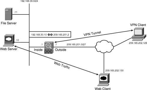
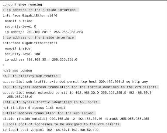
Figure 11-14 shows network topology for SecureMe’s London’s office. It has a Cisco ASA that it uses to provide VPN services for remote users. These users use the security appliance to connect to a file server to access their home directories. SecureMe does not want its broadband VPN users to fully utilize the bandwidth for its office. Therefore, it is interested in using QoS for the VPN tunnels to restrict the users to 256 Kbps. SecureMe also hosts a web server at this location. However, it prefers to prioritize the web traffic from the server to the Internet-based web clients.
Figure 11-14 SecureMe Network Using QoS for VPN Tunnels
Note
Refer to Chapter 17, “IPSec Remote-Access VPNs,” for detailed VPN configuration examples.
Configuration Steps Through ASDM
The relevant configuration through ASDM is discussed here. These configuration steps assume that you have IP connectivity from the ASDM client to the management IP address of the security appliance. The management IP address is 172.18.82.64.
Step 1. Navigate to Configuration > Device Management > Advanced > Priority Queue. Click Add and specify the following attributes:
• Interface: outside
• Transmission ring Limit: 200
Step 2. Navigate to Configuration > Firewall > Service Policy Rules, select the pull-down Add list, and click Add Service Policy Rules. Configure the following Service Policy Rule:
• Interface: Outside–(Create New Service Policy)
• Policy Name: OutsideQoSPolicy
• Description: Policy for VPN and Web on Outside Interface. Click Next when you are finished.
Step 3. Under “Traffic Selection Criteria,” specify a traffic class name of web-traffic. Select source and destination IP addresses (uses ACL) as the Traffic Match Criteria and click Next. Configure the ACL using the following information:
• Action: Match
• Source: 209.165.201.2
• Destination: any
• Service: tcp
• More Options > Source Service: tcp/http. Click Next.
Step 4. Under “Rule Action,” click the QoS tab and select the Enable Priority for this Flow option. Click Finish when you are finished.
Step 5. Navigate to Configuration > Firewall > Service Policy Rules and select the previously defined policy map. Click the pull-down Add list and select Insert After. Configure the following Service Policy Rule:
• Interface: inside–OutsideQoSPolicy
Step 6. Under “Traffic Selection Criteria,” specify a traffic class name of VPNQoSClass. Select Tunnel Group as the Traffic Match Criteria and click Next. Select the tunnel group SecureMeIPSec to apply the QoS policies. Also select the Match Flow Destination IP Address option.
Step 7. Under “Rule Action,” click the QoS tab and select the Enable Policing option. Specify the following information:
• Input policing: Checked
• Committed Rate: 256000 bits/second
• Confirm Action: transmit
• Exceed Acton: drop
• Burst Size: 48000 bytes. Click Finish when you are finished.
Configuration Steps Through CLI
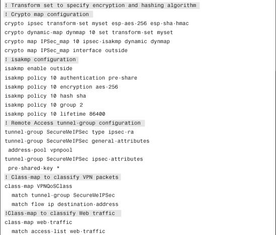
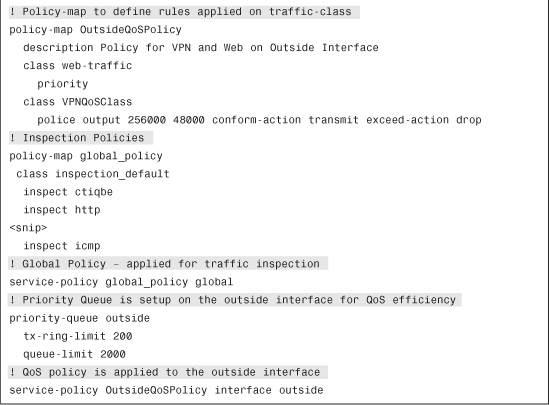
Example 11-11 shows the running configuration of the security appliance in London. A class map called VPNQoSClass is configured to match all the packets destined to the VPN group called SecureMeGroup. To prioritize Internet users’ access to the web server, another class map called web-traffic is set up. The traffic is matched against an ACL that is configured to identify TCP port 80 packets. Both these classes are linked to a policy map called OutsideQoSPolicy, where the VPN traffic is rate-limited to 256 Kbps for normal traffic with a burst rate of 48000 bytes. The security appliance is also configured to prioritize web traffic passing through it. The policy is then applied to the outside interface.
Example 11-11 Full Configuration of the ASA in Chicago Using QoS
Monitoring QoS
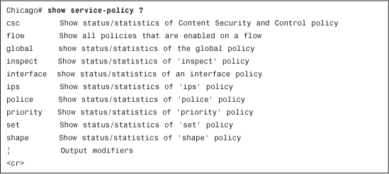
Cisco ASA includes a set of show commands to check the health of the security appliance and to ensure guaranteed QoS through the security appliance. These commands are also helpful in isolating any configuration-related issues. Most of the QoS-related commands start with show service-policy, as shown in Example 11-12.
Example 11-12 Options Available in the show service policy Command
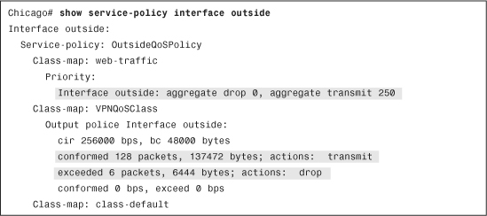
The show service-policy interface command displays the QoS interface policy name of the class map, along with the configured policies within each class. In Example 11-13, two class maps are configured: VPNQoSClass and web-traffic. The VPNQoSClass class is configured to rate-limit the traffic to 256,000 bps with burst size of 48,000 bytes. The security appliance dropped 6 packets because they exceeded the rate-limiting policies, and transmitted 128 packets. On the other hand, the web-traffic class, being the priority class, transmitted 250 packets.
Example 11-13 Output of show service-policy interface outside Command
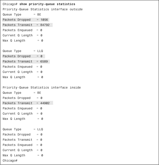
The robust CLI of the security appliance enables you to monitor the depth of interface priority queues. As shown in Example 11-14, show priority-queue statistics displays the queue statistics of the inside and outside interfaces. There are two queue types for each interface: one for the priority traffic (LLQ) and the other for best-effort (BE) traffic. The outside interface best-effort queue transmitted 84,792 packets and dropped 1056. The priority queue, shown as LLQ, forwarded 6589 packet and dropped none. The inside interface transmitted 44902 packets on the best-effort queue.
Example 11-14 Output of show priority-queue Command
Summary
QoS is a robust feature that provides network professionals a means to prioritize time-sensitive and critical data over regular traffic. The three modes—traffic prioritization, traffic shaping, and traffic policing—can be deployed in Cisco ASA to guarantee that important traffic goes through during network congestion. Cisco ASA enables you to fine-tune the QoS engine by setting the transmit ring and priority queue depths to control data delay. This chapter also showed you how to monitor traffic statistics, such as the number of packets matching the priority and best-effort QoS policies.