
Chapter 11
Relationship Between Microstructure and Hydrogen Storage Properties of Nanomaterials
Abstract
The influence of particle size, crystallite size, and lattice defects on hydrogen storage capacity and absorption–desorption kinetics of nanostructured materials are overviewed. It is shown that the particle and crystallite sizes and catalyst play two different roles in the sorption process. By decreasing the particle and crystallite sizes, the required diffusion path of hydrogen is drastically reduced that enhances the sorption kinetics significantly. At the same time, catalysts have a promoting effect on dissociation or recombination of hydrogen molecules on the particles' surfaces, and they also act as chemisorption sites. The lattice defects (dislocations, stacking faults, and twin boundaries) facilitate the diffusion of hydrogen and the nucleation of hydride phases. It is revealed that large amounts of dislocations and/or planar faults are formed due to stresses induced by phase transformations in hydrogenation and dehydrogenation processes. The effect of defects on hydrogen storage capacity of carbon nanotubes is also reviewed.
Keywords
Absorption; Catalyst; Contracting volume model; Desorption; Dislocation; Hydrogen storage; Stacking fault; Twin boundary
11.1. Fundamentals of Hydrogen Storage in Solid State Materials
The application of hydrogen as a fuel can help to overcome the challenges arisen from the fossil fuel–based economy, such as the release of growing amounts of greenhouse gas CO2, the poor urban air quality, and the reduction in the world crude oil supply. Hydrogen can be produced directly from sunlight and water by biological organisms and using semiconductor-based systems similar to photovoltaics, or indirectly via thermal processing of biomass or fossil fuels [1]. The electric power necessary for the decomposition of water into hydrogen and oxygen can be produced by wind turbines or nuclear power plants during off-peak periods. In a hydrogen fuel cell, electricity and water are produced in the following manner. Hydrogen molecules diffuse through a porous anode toward a catalyst made of Pt and are stripped of their electrons and become positively charged ions (protons). The anode and the cathode are separated by a proton-permeable polymeric membrane that allows protons to migrate to the cathode [1]. The electrons formed at the anode-side catalyst cannot migrate through the polymeric membrane, but rather travel in the external circuit between the anode and the cathode, thereby creating electric current. At the cathode side, on the surface of a catalyst the hydrogen protons recombine with electrons and oxygen molecules in air to produce water and heat. This waste heat gives the fuel cell an operating temperature of 60–80 °C.
Hydrogen should be stored for supplying the fuel cells. A possible solution is the storage of hydrogen in chemically bonded state, forming solid-state hydrides in metals or intermetallic compounds. Because of the low pressures involved in metal hydride technologies and the fact that the release of hydrogen takes place via an endothermic process, this method of hydrogen storage is very safe. Additionally, the volumetric hydrogen capacity defined as the mass of hydrogen in a unit volume of the storing device is about 80–160 kg/m3 for solid-state hydrides, which is much higher than that either for compressed hydrogen gas under 80 MPa pressure (∼40 kg/m3) or for liquid hydrogen in a tank at −252 °C (∼71 kg/m3). During the solid-state absorption process, first hydrogen molecules are adsorbed onto the surface and dissociate into atoms by breaking the molecular bonds in favor of new bonds to the surface at chemisorption sites [1]. The energy to overcome the activation potential of dissociation is usually supplied by the vibrational energy. Then, the hydrogen atoms enter the material by diffusion. Following diffusion of hydrogen atoms into the bulk lattice sites, a hydride is formed by nucleation and growth. The formation of hydride starts at the surface of the metal, therefore hydrogen atoms should migrate through the hydride to continue hydrogenation in the metal. In the case of desorption, metal has to be nucleated at the surface, and hydrogen atoms have to diffuse to the surface and recombine to hydrogen molecules, which have to physically desorb [2]. In this case the hydrogen atoms should diffuse through the metal formed at the surface of grains [3].
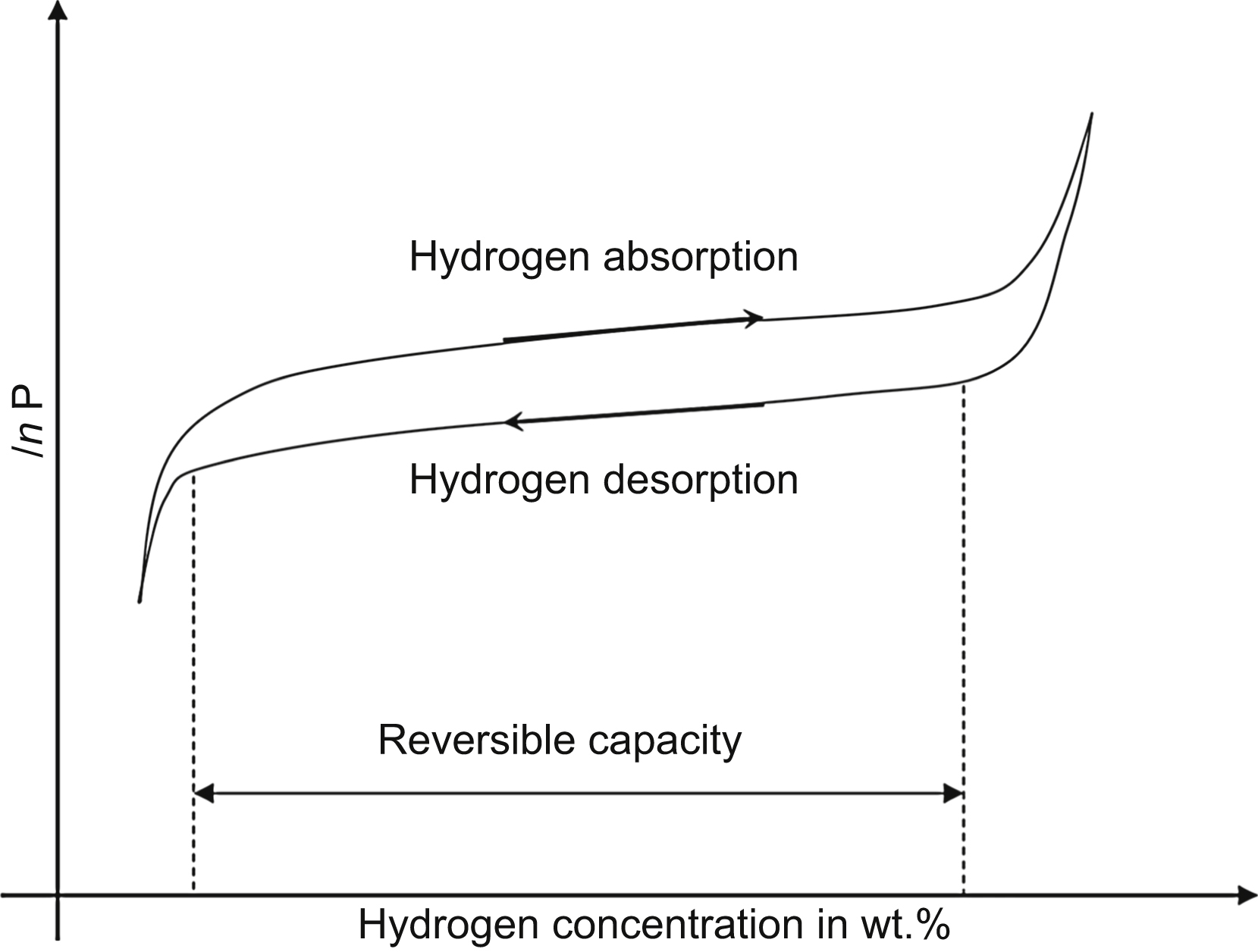
The absorption–desorption behavior can be characterized by the pressure–composition isotherm depicted schematically in Fig. 11.1. This curve can be obtained by measuring the hydrogen pressure outside the hydrogen storing material as a function of hydrogen concentration in weight percent in the hydrogen storing material during absorption and desorption at a given temperature. The uptake of hydrogen occurs at higher pressure than desorption, which yields a hysteresis in the curve. The origin of hysteresis is mainly attributed to the excess of energy required to override the lattice strains occurring upon hydrogen absorption or to the production of misfit dislocations between the initial and the hydride phases. The metal initially dissolves only small amount of hydrogen, which creates a solid solution of hydrogen in the metal matrix [1]. As the hydrogen pressure and hydrogen concentration in the metal are increasing, interactions between hydrogen and metal atoms become locally important, and nucleation and growth of a new metal hydride phase are observed. In the plateau region, a mixture of solid solution and metal hydride phases exists. The length of plateau determines the reversible capacity of the material that gives the relative weight fraction of hydrogen that can be stored reversibly with a small pressure variation (see Fig. 11.1). The desorption temperatures for high-capacity hydrides at a pressure of 1 bar are between 110 and 600 °C. At this atmospheric pressure, the reversible capacity for these materials varies between 5 and 14 wt.%. With increasing temperature, the plateau pressure increases and beyond a critical temperature, the plateau region disappears. The relation between the pressure P measured at the middle of the absorption plateau and the temperature T is given by the Van't Hoff equation [1]:
![]() (11.1)
(11.1)
where P0 is the atmospheric pressure, ΔH and ΔS are the enthalpy and entropy changes during the hydriding reaction, respectively, T is the absolute temperature, and R is the universal gas constant. For almost all hydrides the enthalpy and entropy changes during hydriding reaction are negative, i.e., the hydriding reaction is exothermic and dehydriding reaction is endothermic. The entropy change has nearly constant value of ΔS ≈ −130 J/mol K for all the solid state hydrogen systems while ΔH varies between −20 and −200 kJ/mol for different materials [1].
Basically, there are three models describing absorption/desorption kinetics: (1) surface reaction, (2) Johnson–Mehl–Avrami–Kolmogorov (JMAK), and (3) contracting volume (CV) models of phase transformations [4]. The surface reaction model assumes that the slowest step of reaction is the chemisorption, i.e., the dissociation or recombination of hydrogen molecules on the particles' surfaces. In this case, the transformed fraction, Vrel, linearly depends on time t as
![]() (11.2)
(11.2)
where kCS is the reaction constant. In JMAK theory of phase transformations, it is assumed that the nucleation and growth of the new (hydride) phase starts randomly in the bulk and at the surface. The transformed fraction as a function of time can be given as
![]() (11.3)
(11.3)
where kJMAK is the reaction constant and n depends on the dimensionality of the growth of the new phase nuclei (e.g., n = 2 corresponds to two-dimensional growth and n = 3 to three-dimensional growth). Assuming that the hydrogen diffusion is very fast, the transformation rate is controlled by the (constant) velocity of the metal/hydride interface [4].
If the nucleation of the hydride phase starts at the surface of the metal particle and the growth continues from the surface into the bulk, the CV model is used. The analytical model assumes that a thin layer of transformed phase on the surface of the particle already exists. The kinetics can be described as
![]() (11.4)
(11.4)
where n depends again on the dimensionality of the growth (n = 2 and 3 for two and three dimensional growth processes, respectively). The reaction constant kCV is proportional to the velocity of the metal/hydride interface and inversely proportional to the radius of the metal particle. If the hydrogen diffusion is fast enough, the rate of transformation is determined by the constant velocity of the interface. The difference in growth mechanism for JMAK and CV models is illustrated in Fig. 11.2 [4].

Figure 11.2 Schematic depiction of phase transformation according to (a) Johnson–Mehl–Avrami–Kolmogorov and (b) contracting volume models. The dark areas represent the growing new phase.
If the diffusion of hydrogen through the transformed phase is the rate-limiting step, the interface velocity decreases with time. In case of CV and three-dimensional growth, the relationship between the transformed volume fraction and the time can be given as
![]() (11.5)
(11.5)
11.2. Microstructure and Hydrogen Storage in Nanomaterials Processed by Severe Plastic Deformation
During absorption process, hydrogen atoms first migrate along the grain boundary network and then they begin to diffuse into grain interiors. Therefore, the nanostructured state of materials used for hydrogen storage is beneficial from the viewpoint of fast absorption and desorption of hydrogen. The nanocrystalline microstructure is usually achieved by severe plastic deformation, such as ball milling of powders or high-pressure torsion (HPT) of bulk materials. During milling, both the powder particle size and the grain size inside the particles decrease leading to a faster diffusion of hydrogen along the particle surfaces and the grain boundaries. Additionally, grain boundaries are favorable nucleation sites for the formation and decomposition of the hydride phase. Moreover, high-energy milling (1) breaks the oxide layers and passivation coatings on particles' surfaces, hence exposure of fresh catalytic sites for dissociation of hydrogen molecules and (2) increases the densities of lattice defects (e.g., dislocations, stacking faults, and twin boundaries) that also serve as paths for fast diffusion of hydrogen [1]. Moreover, addition of catalysts to hydriding material further increases the rate of sorption by assisting the dissociation of hydrogen molecules. Thus, the three dominant factors influencing the sorption properties are particle size, grain size, and catalyst.
The effects of grain and particle sizes on hydrogen storage properties were studied extensively on milled MgH2 powders. It was shown in Chapter 4 that the grain size determined by electron microscopy and the crystallite size obtained by X-ray line profile analysis agree well for ball milled materials, therefore the two terms will be used equivalently in this chapter. Magnesium is considered as one of the most attractive hydrogen storage materials, mainly because of high-storage capacity (7.6 wt.%), lightweight, and low cost [1]. During hydrogenation, Mg having hexagonal crystal structure transforms to tetragonal MgH2. Hydrogen atoms bind too strongly with the Mg atoms, i.e., the absolute value of formation enthalpy of MgH2 is high (−75 kJ per mol H2) [1], therefore the hydride needs to be heated up to very high desorption temperatures (∼350 °C) to release hydrogen gas at atmospheric pressure (∼1 bar). Additionally, the absorption and desorption are also very slow at temperatures ∼350 °C that impedes the direct use of magnesium as hydrogen storage material. To convert Mg completely to MgH2, it requires more than 50 h at 350 °C [5]. The slow sorption kinetics at lower temperatures are mainly due to the low dissociation ability of hydrogen gas molecules on the metallic Mg surface and the slow diffusion of hydrogen through the hydride formed on the surface of Mg particles. Ball milling of Mg in hydrogen atmosphere yields a nanocrystalline material with the crystallite size of ∼30 nm that can absorb about 6 wt.% hydrogen in much shorter time, 120 min, and at lower temperature, 300 °C, than in the case of coarse-grained Mg. Milling MgH2 instead of pure Mg results in even smaller crystallite size of ∼10 nm that yields very short duration, 10 min, of sorption at 300 °C. The addition of suitable catalysts (e.g., Nb2O5 leads to very short hydrogen absorption and desorption times of less than 2 min at 300 °C for MgH2 with high capacity of 7 wt.% hydrogen) [6]. The milling of MgH2 is usually carried out in hydrogen atmosphere to prevent the decomposition of MgH2 into Mg and H2. The effects of particle and crystallite sizes, and the catalyst on the absorption and desorption behaviors at 300 °C are illustrated in Fig. 11.3 [2]. The absorption and desorption are performed under 8 bar hydrogen and in vacuum, respectively. The conventional MgH2 powder with coarse particles (>10 μm) and crystallites (>1 μm) cannot be loaded or unloaded with hydrogen at 300 °C in reasonable times. The powders processed by ceramic ball milling for 20 and 700 h have comparably small crystallite sizes in the range of 5–20 nm, while the particle sizes are different, ∼5 and ∼0.5 μm, respectively. This difference results in a much faster sorption kinetics for the sample milled for 700 h. It should be noted that the reduction of grain and particle sizes also decrease the hydrogen desorption temperature [7].
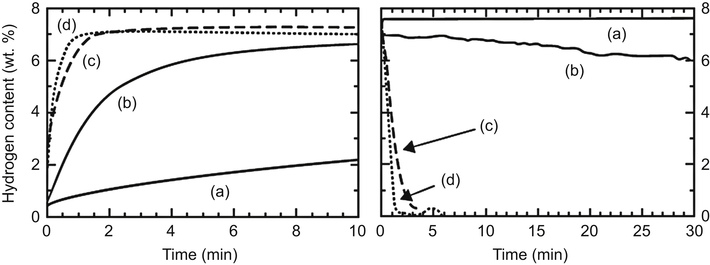
Figure 11.3 Absorption (left side) and desorption curves (right side) of (a) conventional coarse-grained MgH2; (b) nanocrystalline MgH2 processed by ball milling for 20 h; (c) MgH2 ball-milled for 700 h, and (d) Nb2O5-catalyzed ball-milled MgH2. Reprinted from M. Dornheim, S. Doppiu, G. Barkhordarian, U. Boesenberg, T. Klassen, O. Gutfleisch, R. Bormann, Hydrogen storage in magnesium-based hydride composites, Scripta Materialia 56 (2007) 841–846 with permission from Elsevier.
The addition of Nb2O5 catalyst to MgH2 powder before milling increases further the rate of absorption and desorption of hydrogen (see Fig. 11.3). However, the particle/crystallite size and catalyst play two different roles in the sorption process. By decreasing the particle and crystallite sizes, the required diffusion path of hydrogen is drastically reduced that enhances the sorption kinetics significantly. However, the size reduction influences neither the adsorption of hydrogen molecules on the surface, nor the ease of their dissociation. At the same time, the metal oxide catalysts seem to have a promoting effect on dissociation or recombination of hydrogen molecules on the particles' surfaces and they also act as chemisorption sites [6], resulting in a decrease of the activation energy of hydrogenation and dehydrogenation [4,7]. Moreover, the hard Nb2O5 catalyst particles in the milled powder blend results in an additional slight decrease in MgH2 particle size that also contributes to better sorption kinetics [7]. It seems that above a critical fraction, additional catalyst does not yield further acceleration of absorption or desorption. In the case of Nb2O5 catalyst added to MgH2, this critical amount is ∼0.5 mol% when hydrogenation and dehydrogenation are performed under hydrogen atmosphere at 8.4 bar and in vacuum, respectively [4]. After 100 h milling, the activation energy of desorption is drastically decreased from values around 120 kJ/mol for the chemisorption of uncatalyzed nanocrystalline magnesium hydride down to about 62 kJ/mol by increasing the catalyst content up to ∼0.5 mol%. Above this catalyst content, further decrease of activation energy is not observed. As the activation energy of desorption for MgH2 with coarse particles is ∼140 kJ/mol, the reduction of particle and crystallite sizes in MgH2 during milling yields only a slight decrease in the activation energy.
By comparing the experimental absorption and desorption data with Eqs. (11.2)–(11.5) for MgH2 powder milled with Nb2O5 catalyst, the absorption behavior is best described by the three-dimensional diffusion controlled CV model (Eq. 11.5) [4]. In the dehydrogenation process, generally chemisorption (recombination of hydrogen molecules on the surface) is the rate controlling mechanism (Eq. 11.2) but when both milling time and catalyst content are high, CV model with two-dimensional growth (Eq. 11.4, n = 2) best describes the kinetics. Both the increase of milling time—leading to the reduction of particle and crystallite sizes—and Nb2O5 content increase the desorption reaction constants, kCS and kCV for chemisorption and CV model, respectively [4]. These results indicate that during desorption the hydrogen diffusion through the dehydrided Mg is fast and not rate limiting. On the other hand, the absorption of hydrogen in Mg is mainly controlled by the diffusion of hydrogen through the hydride phase formed at the surface of the particles. This difference between the absorption and desorption behaviors can be explained by the smaller diffusion constant of hydrogen through MgH2 compared to Mg [8]. The increment in the reaction constant for absorption with increasing the catalyst content and the milling time can be explained by an enhanced dissociation rate of hydrogen molecules resulting in a higher gradient of the hydrogen chemical potential and thereby in a faster diffusion of hydrogen through the formed magnesium hydride phase [4]. Longer milling reduces the particle and crystallite sizes yielding a faster diffusion of hydrogen along boundaries. When a very high fraction of catalysts is added and the long milling time yields a nanosized dispersion of catalyst particles, the recombination of hydrogen atoms to molecules at the surface is fast and no longer the rate-limiting step in the desorption process. In this case, the powder particles are covered by a dehydrided magnesium phase and the interface between the dehydrided magnesium and the magnesium hydride moves from the particles' surfaces along the crystallite boundary areas into the volume of the powder particles because the interface velocity along crystallite boundaries is significantly faster than perpendicular to the crystallite boundary area. As a consequence, the desorption kinetics is governed by the interface mobility of the transformed phase along the two-dimensional network of crystallite boundaries that is reflected by the value n = 2 in CV model [4]. It is noted that taking the size distribution of crystallites into account, the kinetics and the reaction constants of the different transformation models are considerably modified compared to the models for monodisperse crystallites [9].
The severe plastic deformation of bulk Mg and its alloys also improves the hydrogen storage properties [10–16]. For instance, in 3N purity Mg processed by HPT up to 10 revolutions under a pressure of 6 GPa, total hydrogen absorption of 6.9 wt.% is achieved at 150 °C under a hydrogen pressure of 3 MPa. The dislocation density reaches its maximum value after 1/4 revolution; however, after 10 turns both the dislocation density and the grain size are reduced due to primary recrystallization. Although the dislocation density is much larger in the sample processed up to 1/4 revolution than after 10 turns, the hydrogen storage capacity of the former material is comparably smaller (<0.5 wt.%) than that of the annealed Mg with very large grain size of ∼1.6 mm [16]. After 10 revolutions, absorbed hydrogen is increased to 6.9 wt.% and the hydrogen absorption rate is 12 times faster than for the annealed sample or the sample after 1/4 turn that can be attributed to significant grain refinement and an increase in the area fraction of high-angle grain boundaries [16]. It is concluded that in HPT-processed Mg high-angle grain boundaries play a more effective role than dislocations in the hydrogen absorption. The improvement of hydrogen storage properties is also observed for bulk Mg-Ti alloys processed by accumulative roll bonding [17].
The effect of stacking faults and twin boundaries on hydrogen storage properties is investigated only in a few studies [1,18–20]. For instance, high density of stacking faults is formed during ball milling of battery-grade Ni(OH)2 used in the positive electrodes of rechargeable alkaline nickel metal hydride batteries. Ni(OH)2 has a hexagonal structure with well-stacked basal planes that are bonded by weak Van der Walls forces. Ball milling of Ni(OH)2 yields stacking faults on basal planes that facilitates accommodation of hydrogen ions between basal planes.
11.3. Change of Defect Structure During Dehydrogenation–Hydrogenation Cycles
The dehydrogenation–hydrogenation cycle leads to changes in the microstructure of hydrogen storage nanomaterials and therefore a variation of their absorption/desorption kinetics [21]. Fig. 11.4 shows the first and the second desorption curves measured in vacuum for MgH2 ball-milled for 10 h at 300 °C. The first dehydrogenation process needs longer time (∼80 min) than the second one (∼10 min). For subsequent cycles, further changes in the desorption curves are not observed. The longer dehydrogenation time in the first cycle can be attributed to the nonactivated surface of the particles in the as-milled powder. In the activation process occurring during the first cycle, Mg nuclei precipitate on surfaces of the as-milled MgH2 particles below the magnesium oxide and hydroxide passivation layer. As the nuclei grow, the induced strains cause the fracture of the passivation layer, exposing a fresh activated surface [22]. After the first cycle, further desorption processes take shorter times due to the activated surfaces of particles. In contrast to the desorption behavior, the first absorption curve is not different significantly from the subsequent ones, indicating that no further activation of the powder occurs during the absorption interval of the first full cycle (the cycle starts with desorption). The absorption was measured under a hydrogen pressure of 8 bar.
The MgH2 sample milled for 10 h at 300 °C has a mean crystallite and particle sizes of 9 and 780 nm, respectively. The variation of the average crystallite size of MgH2 as a function of the number of desorption–absorption cycles is shown in Fig. 11.5. During the first full dehydrogenation–hydrogenation cycle at 300 °C, the average crystallite size increases from 9 to 20 nm, while the crystallite size distribution becomes narrower, i.e., the crystallite structure becomes more homogeneous [22]. Further dehydriding/hydriding treatments increase the width of size distribution, while the average crystallite size remains unchanged. After six cycles the crystallite size distribution is slightly wider than for the as-milled MgH2 powder. The crystallite structures in the as-milled MgH2, and after the first and the second desorption–absorption cycles are illustrated in Fig. 11.6. The crystallite-growth in MgH2 during the first cycle is caused by the high temperature and the relatively long time of desorption required for the first full cycle at 300 °C. After activation, the desorption occurs on a considerably shorter time scale, therefore some residual MgH2 inclusions may remain inside the larger Mg crystallites, since the transformed Mg spreads from the boundaries toward the interiors of crystallites according to CV model (see Section 11.1). The relative volume fraction of the possible residual MgH2 inclusions has no detectable contribution to the measured maximum capacity. For example, an MgH2 inclusion inside a crystallite, with a radius of 10% of the initial crystallite radius, has only a 0.1% contribution to the total volume of the crystallite. These inclusions appear as very small crystallites in the microstructure after hydrogenation in the second cycle (see Fig. 11.6c), therefore yielding the broadening of crystallite size distribution. Contrary to the variation of the crystallite size distribution inside the particles with increasing number of cycles, the size and the morphology of powder particles remain unchanged during repeated dehydriding/hydriding. It is noted that despite the smaller crystallite size in the as-milled sample, the desorption lasts longer in the first cycle than during the subsequent cycles because of the nonactivated surface of particles in the beginning of the first dehydrogenation. It seems that the addition of catalyst (e.g., Nb2O5 to MgH2) hinders the growth of crystallites during absorption–desorption cycles at high temperatures [23].
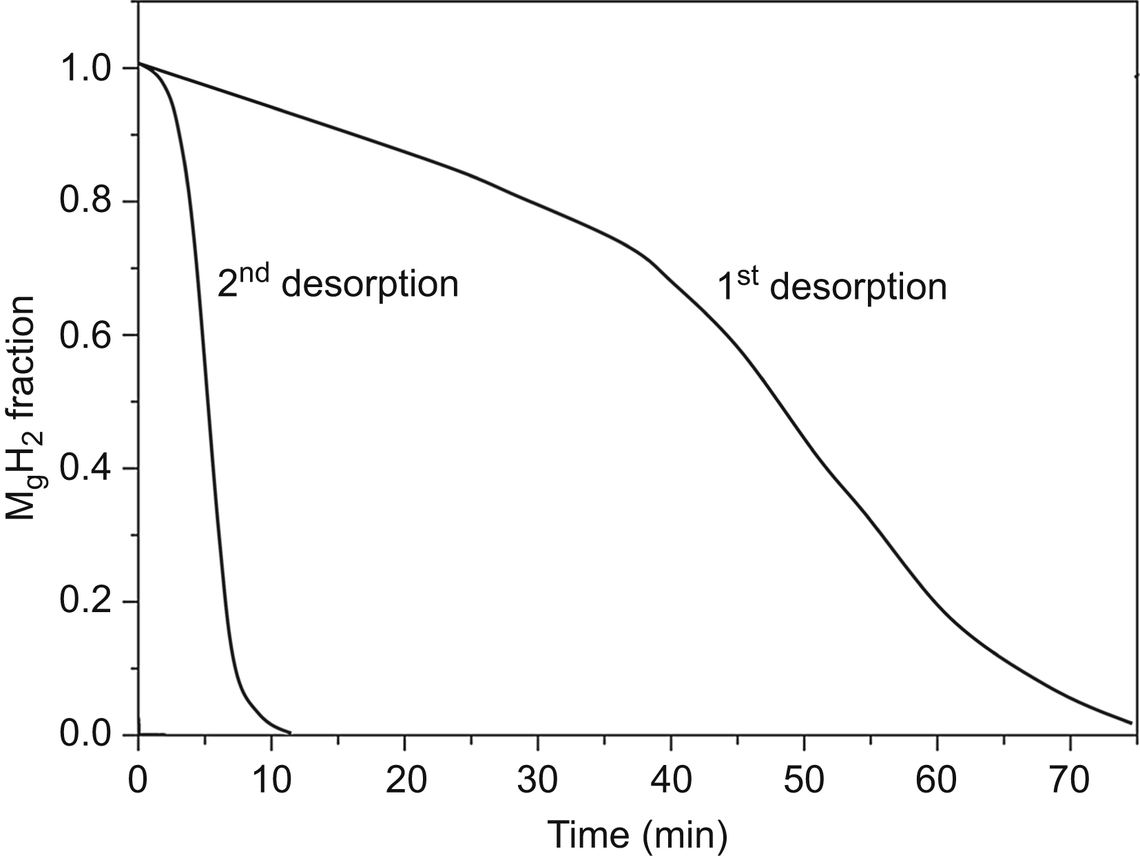
Figure 11.4 The first and the second desorption curves measured in vacuum at 300 °C for MgH2 ball-milled for 10 h. The first desorption corresponds to the activation of the powder. The data are taken from D. Fátay, T. Spassov, P. Delchev, G. Ribárik, Á. Révész, Microstructural development in nanocrystalline MgH2 during H-absorption/desorption cycling, International Journal of Hydrogen Energy 32 (2007) 2914–2919.

Figure 11.5 Variation of the average crystallite size of MgH2 as a function of the number of dehydrogenation–hydrogenation cycles. Reprinted from D. Fátay, T. Spassov, P. Delchev, G. Ribárik, Á. Révész, Microstructural development in nanocrystalline MgH2 during H-absorption/desorption cycling, International Journal of Hydrogen Energy 32 (2007) 2914–2919 with permission from Elsevier.

Figure 11.6 Schematic depiction of the crystallite structure in MgH2 (a) immediately after milling, after (b) the first and (c) the second dehydrogenation–hydrogenation cycles. Reprinted from D. Fátay, T. Spassov, P. Delchev, G. Ribárik, Á. Révész, Microstructural development in nanocrystalline MgH2 during H-absorption/desorption cycling, International Journal of Hydrogen Energy 32 (2007) 2914–2919 with permission from Elsevier.
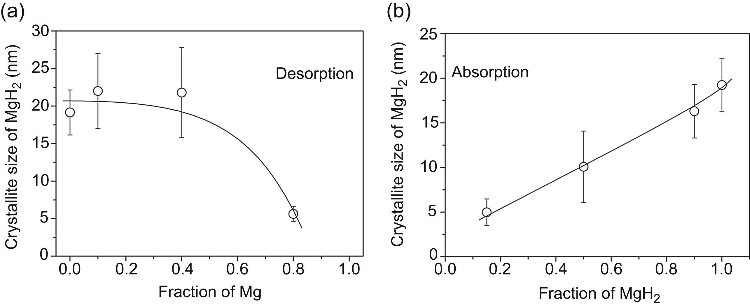
Figure 11.7 Variation of the average crystallite size of MgH2 as a function of the fraction of Mg and MgH2 during (a) desorption and (b) absorption, respectively. Reprinted from Á. Révész, D. Fátay, Microstructural evolution of ball-milled MgH2 during a complete dehydration-hydrogenation cycle, Journal of Power Sources 195 (2010) 6997–7002 with permission from Elsevier.
The variation of the crystallite size in the ball-milled MgH2 within one full desorption–absorption cycle is investigated during the fourth cycle. Fig. 11.7a and b shows the variation of the crystallite size of MgH2 determined during desorption and absorption, respectively. It can be seen that the initial value of 20 nm remains practically unchanged up to 40% of the transformed volume fraction of Mg. At the fraction of 80% Mg, the remaining small amount of MgH2 has very small crystallite size of 3 nm [24]. A considerably different crystallite size evolution takes place during the transformation of Mg into MgH2 (absorption), as it increases almost linearly up to 19 nm when the amount of MgH2 reaches 100%. The change of the crystallite size during desorption can be explained by the CV theory of transformation of MgH2 into Mg. If the transformation of MgH2 to Mg spreads from the boundary into the interior of a crystallite according to the CV model, then the volume fraction of the remaining MgH2 phase (Vhydride) decreases as:
 (11.6)
where d0 and d is the initial (before desorption) and the actual crystallite sizes of the hydride phase, respectively. The normalized crystallite size,  can be expressed as a function of the fraction of the formed Mg phase (VMg = 1 − Vhydride) by the following formula:
![]() (11.7)
(11.7)

Figure 11.8 Variation of the normalized crystallite size of MgH2 as a function of the transformed fraction of Mg during desorption according to Eq. (11.7).
Fig. 11.8 shows the normalized crystallite size as a function of VMg according to Eq. (11.7). Similarly to the experimental results presented in Fig. 11.7a, the crystallite size decreases slowly in the beginning of desorption while it falls steeply to a very small value at the end of transformation. Considering the size distribution of crystallites in MgH2 phase, the smallest crystallites in the distribution disappear first during dehydrogenation, thereby resulting in a larger average crystallite size of MgH2 for low transformed fractions of Mg than the values presented in Fig. 11.8. This effect lowers the rate of the decrease of crystallite size in the beginning of transformation yielding an apparent plateau as it was found experimentally (see Fig. 11.7a). The dislocation density in the tetragonal MgH2 phase was not determined but in Mg after dehydrogenation the dislocation density was as small as 6 × 10¹³ m−2.
In addition to the crystallite size, the type and densities of lattice defects (dislocations, stacking faults, and twin boundaries) may change during hydrogenation and dehydrogenation processes. For instance,  -type and
  -type edge dislocations with the Burgers vectors of
  and
and  on the
  prismatic slip plane are formed in coarse-grained hexagonal LaNi5, LaNi4.5Cu0.5, and LaNi4.5Fe0.5 during the first absorption process [25–27]. It is revealed that the density of these dislocations is ∼1015 m−2 and they are introduced to accommodate the lattice mismatch between the metal-hydrogen solid solution and the metal hydride. It is proposed that the formation of these misfit dislocations needs an excess pressure that is the main reason of the much higher pressure during the first absorption compared to the first desorption (see the hysteresis in Fig. 11.1). In contrast, dislocations are not observed in LaNi4.5Si0.5, LaNi4.5Al0.5, and LaNi4.75Sn0.25, which show little or no hysteresis in the hydrogen pressure–composition isotherms [27]. In these alloys, misfit strains are accommodated by crack formation that occurs more readily than the multiplication of dislocations during hydrogenation. During hydrogen absorption–desorption in coarse-grained Ti-V-Mn alloy with body-centered cubic (bcc) structure, stacking faults and twin boundaries are also introduced in addition to dislocations. These twin boundaries and stacking faults are formed on the {110} and {111} planes of the bcc alloy and the face-centered cubic (fcc) hydride, respectively, to accommodate shear strains developed during phase transformation [28].
The defect structure evolved in the hydride phase during the absorption process is strongly influenced by the microstructure of the initial material. This effect was investigated carefully for Mg2Ni [29]. Mg2Ni is also a frequently used hydrogen storage material as its hydride is less stable than that of Mg, thereby accelerating the desorption and/or lowering the dehydrogenation temperature, although the storage capacity is smaller. For instance, Mg2Ni is able to form Mg2NiH4 with a hydrogen storage capacity of 3.6 wt%. The hydrogen release of this hydride occurs at a lower temperature (about 250 °C) than that of MgH2 [29]. When ball-milled Mg2Ni with 15–20 nm crystallite size is hydrogenated at 200 °C, monoclinic low-temperature phase of Mg2NiH4 forms that contains a much larger amount of stacking faults and/or twin boundaries than the hydride obtained by hydrogenation of coarse-grained Mg2Ni at the same temperature. Most probably, the large distortions in the ball-milled Mg2Ni are relaxing by the formation of stacking faults and twins during hydrogenation. Dislocations, stacking faults, and twin boundaries with very large densities may also form in hydrogen storage materials processed without application of severe plastic deformation. For example, after dehydrogenation of Mg2NiH4 produced by hydriding combustion synthesis, Mg2Ni is obtained with very high dislocation density of ∼1017 m−2, which develops due to stresses induced by phase transformations in combustion synthesis and subsequent dehydrogenation [30]. The high defect density improves the sorption kinetics by increasing diffusivity and the number of potential sites for new phase nucleation.
11.4. Effect of Defects on Hydrogen Storage Properties of Carbon Nanotubes
Carbon nanotubes (CNTs) are obtained in two different main forms characterized by the structure of their wall: the single-walled nanotubes (SWNTs) and the multiwalled nanotubes (MWNTs). SWNTs consist of a graphene sheet rolled up into a cylinder of a few nanometers diameter and several microns length [31]. An MWNT is an arrangement of coaxial SWNTs ranging in number from 2 up to about 50. The diameters of these MWNT range from a few to tens of nanometers and their length is of the order of micrometer. There are many methods to produce CNTs among which CNTs grown by chemical vapor deposition have higher defect density compared with CNTs synthesized by arc discharge and laser ablation methods [32]. Defects can also be introduced after growth of CNTs by different methods like milling [33], oxidation [34], nitric acid treatment [31], potassium hydroxide treatment [35], plasma etching [36], and irradiation [37]. During heat treatment of pristine CNTs, both defect generation and defect annealing processes take place [32].
Due to the lightweight and high-specific surface area of CNTs, they are good candidates for hydrogen storage. In SWNTs, hydrogen can be adsorbed at the exterior of the tube wall by forming H C bonds or in the middle of the tubes by HH bonds. The adsorption into the interior wall of the tube is also possible but not stable and hydrogen form HH bonds inside the tube [3]. MWNTs can adsorb hydrogen between the walls of the coaxial tubes. The amount of hydrogen stored by both physisorption due to van der Waals forces and chemisorption in as-prepared CNTs is usually less than 1 wt.%, although in some cases higher storage capacities of 4–7 wt.% are reported [3]. The scattering in the experimentally obtained capacity values can be explained by the nonuniform morphology of CNTs (diameter, length, and wall thickness, etc.) and the variation of the purity level [34]. Opening of CNTs by removing buckyball structured caps from the ends of nanotubes by milling, nitric acid treatment, or oxidative technique improves storage capacity because hydrogen molecules cannot penetrate through the carbon atom hexagons in the wall [31]. Additionally, the introduction of defects into CNT activates hydrogen adsorption and enhances the chemisorption, thereby yields a large enhancement of hydrogen adsorption and desorption. Defects in CNTs can be produced by ion irradiation at keV to MeV energies [37]. High-energy ions produce atomic displacements within the six-membered carbon rings. In addition, the displaced atoms or knock-ons may have sufficient energy to displace additional atoms. The damaged region is collectively referred to as a collision cascade and consists of single vacancies, divacancies, and displaced atoms. The knock-on atoms will lose their energy through multiple scattering until they are thermalized and adsorbed onto the nanotube walls as adatoms. These defects in SWNTs are illustrated in Fig. 11.9a. Subsequent thermal treatment after ion irradiation may transform the vacancies and the adatoms into nonhexagonal rings and/or pentagon/heptagon Stone–Wales (SW) defects as illustrated in Fig. 11.9b. For comparison of the hydrogen storage capacity of SWNTs irradiated with a fluence of 5 × 10¹⁶ H-ions/cm2 with a nontreated sample, first both specimens were hydrogenated under a pressure of 83 bar and at 200 °C for 12 h. Then, during desorption at 450 °C eight times larger amount of hydrogen released from the irradiated material than from the untreated CNTs.
Pores and defects on MWNT walls can also be generated by pulse oxidation at 600 °C as seen in Fig. 11.10a [34]. The pristine MWNTs can uptake only 0.1 wt.% hydrogen at 300 °C under ambient pressure while the defective MWNTs can store 0.5 wt.% hydrogen, indicating that to create defects on MWNTs is an effective route for enhancing the hydrogen storage. The capacity of the pristine MWNTs can be increased from 0.1 to 1.8 wt.% by doping with Pd–Ni catalyst that promotes adsorption and dissociation of hydrogen molecules. When the defective MWNTs are doped with Pd–Ni, the superposition of the effects of the defects and the catalyst yields a very high capacity of 6.6 wt.% hydrogen. Pd–Ni doping over defective MWCNTs not only increases the hydrogen storage capacity, but also decreases the hydrogen release temperature from 677 to 337 °C. Pd–Ni alloy forms nanoparticles with the size of 10–20 nm on the walls of MWNTs having similar diameters (see Fig. 11.10b). The majority of hydrogen is stored in the form of CH and CH2 species attached to the walls of nanotubes. The carbon atoms located at the defective parts of CNTs have a dangling bond and hence are able to associate with atomic hydrogen to form CH or CH2 species [34]. This chemisorption is the main reason of the increased capacity of defective CNTs with catalyst. Without defects and the metal catalyst assistance, the hydrogen molecule is not easily dissociated to atomic hydrogen over the CNTs and unlikely to form the CH bond. As a consequence, in pristine CNTs hydrogen is rather stored in molecular form with the help of physisorption.

Figure 11.9 Front walls of one and the same single-walled nanotubes just after ion impact (a) and after annealing (b). During annealing the divacancy (D) transformed to an agglomeration of nonhexagonal rings. The numbers in the center of the rings indicate the numbers of atoms that constitute the rings. The single vacancy (S) and the nearby carbon adatom (A) in the upper right-hand corner in (A) transformed to a Stone–Wales 5–7 defect in (B). Reprinted from A.V. Krasheninnikov, K. Nordlund, Irradiation effects in carbon nanotubes, Nuclear Instruments and Methods in Physics Research, Section B: Beam Interactions With Materials and Atoms 216 (2004) 355–366 with permission from Elsevier.

Figure 11.10 TEM images of (a) defective multiwalled carbon nanotubes (MWCNTs) processed by oxidation, (b) defective MWCNTs doped with Pd–Ni catalyst nanoparticles (appeared as black dots). Reprinted from L. Gao, E. Yoo, J. Nakamura, W. Zhang, H.T. Chua, Hydrogen storage in Pd-Ni doped defective carbon nanotubes through the formation of CHx (x = 1,2), Carbon 48 (2010) 3250–3255 with permission from Elsevier.
Pores on the outer surface of MWNTs facilitate the hydrogen spillover process that comprises the dissociation of hydrogen molecules to atomic hydrogen on a metal catalyst and subsequent migration from the metal to the surface of CNTs [35]. Fig. 11.11 compares schematically hydrogen spillover processes for defect free and defective MWNTs. In the former case, the dissociated hydrogen atoms can migrate from the catalyst particles only to the external surface of the CNTs. At the same time, for an MWNT containing pores in the vicinity of catalyst particles, hydrogen atoms easily diffuse and migrate from the external surface into interplanar spacing via the pores, causing hydrogen spillover enhancement and therefore larger storage capacity.

Figure 11.11 Schematic representation of hydrogen spillover in (a) defect free and (b) defective multiwalled nanotubes decorated by catalyst particles. H, atomic hydrogen, H2, hydrogen molecule. Reprinted from C-H. Chen, C-C. Huang, Enhancement of hydrogen spillover onto carbon nanotubes with defect feature, Microporous and Mesoporous Materials 109 (2008) 549–559 with permission from Elsevier.
Ball milling provides a simple and efficient method to introduce defects into CNTs. The collision and friction with the milling balls result in (1) shortening of CNTs by cleavage leading to an increase of specific surface area, (2) opening the ends of CNTs, and (3) increase of defect density. As a consequence, milling improves the hydrogen adsorption properties of CNTs. For instance, the hydrogen adsorption capacity of MWNTs at room temperature under a pressure of 8–9 MPa increases from 0.1 to 0.66 wt% due to milling for 10 h [33]. The variation of capacity is nonmonotonous as first it increases with milling time up to ∼10 h, then decreases to ∼0.2 wt.% after 30–40 h milling and remains unchanged for longer milling times. The decrease of storage capacity for long milling times can be explained by the formation of amorphous carbon having poor hydrogen adsorption properties [33].
Defects on the walls of CNTs can also be introduced by plasma etching. In this process the plasma can be produced in hydrogen gas using a microwave plasma generator [36]. The nonetched MWNTs have ∼0.6 wt.% hydrogen uptake capacity at ambient temperature and under the pressure of ∼11 MPa, while after 2 and 4 h etching processes, the hydrogen storage capacity reaches ∼1.0 and ∼1.4 wt.%, respectively. In addition to the promotion effect of defects on the chemisorption of hydrogen, they also facilitate the access of hydrogen molecules to interlayers and hollow interiors of MWNTs. Without defects on CNT walls, hydrogen has to enter the tubes through the open ends. Additionally, the pores on the external surface of MWNTs can store hydrogen molecules and their contribution to hydrogen capacity linearly increases with the volume fraction of pores [39]. The decoration of MWNTs by Pd nanoparticles after 2 and 4 h etching yields an additional increase of hydrogen storage capacity to 4 and 4.5 wt.%, respectively [36]. Pd catalyst promotes the dissociation of H2 into hydrogen atoms that easily penetrate tube walls and are combined into H2 in interlayers and hollow interiors of CNTs or form CH bonds by chemisorption.
All-electron density functional theory calculations predict good ability of hydrogen storage for defective nitrogen-doped CNTs decorated by Ca atoms [40]. Nitrogen atoms substitute carbon atoms in divacancies, and Ca-adsorption on the hollow site of these defects is energetically favorable. According to the calculations, in a H2 adsorption process the optimized structure is reached when five hydrogen molecules are attached to one Ca atom at divacancies that yield a theoretical storage capacity of ∼3 wt.% without any catalyst.
..................Content has been hidden....................
You can't read the all page of ebook, please click here login for view all page.