3.5. Multiple View Geometry
Multiple view geometry is the subject in which relations between coordinates of feature points in different views are studied. It is an important tool for understanding the image formation process for several cameras and for designing reconstruction algorithms. For a more detailed treatment, see [27] or [24], and for a different approach, see [26]. For the algebraic properties of multilinear constraints, see [30].
3.5.1. The structure and motion problem
The following problem is central in computer vision:
Problem 1. Structure and motion. Given a sequence of images with corresponding feature points Xij, taken by a perspective camera,
![]()
determine the camera matrices, Pi (motion) and the 3D points, Xj (structure), under different assumptions on the intrinsic and/or extrinsic parameters. This is called the structure and motion problem.
It turns out that there is a fundamental limitation on the solutions to the structure and motion problem when the intrinsic parameters are unknown and possibly varying, namely with an uncalibrated image sequence.
Theorem 5. Given an uncalibrated image sequence with corresponding points, it is only possible to reconstruct the object up to an unknown projective transformation.
Proof: Assume that Xj is a reconstruction of n points in m images, with camera matrices Pi according to
![]()
Then H Xj is also a reconstruction, with camera matrices Pi H–1, for every nonsingular 4 × 4 matrix H, since
![]()
The transformation
![]()
corresponds to all projective transformations of the object. ▪
In the same way it can be shown that if the cameras are calibrated, then it is possible to reconstruct the scene up to an unknown similarity transformation.
3.5.2. The two-view case
The epipoles
Consider two images of the same point X as in Figure 3.9.
Figure 3.9. Two images of the same point and the epipoles.
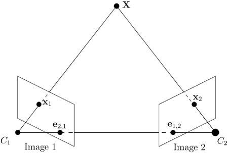
Definition 25. The epipole, ei,j, is the projection of the focal point of camera i in image j. ▪
Proposition 7. Let
![]()
Then the epipole, e1,2 is given by
Equation 3.12
![]()
Proof: The focal point of camera 1, C1, is given by
![]()
that is, ![]() , and then the epipole is obtained from
, and then the epipole is obtained from
![]()
▪
It is convenient to use the notation ![]() . Assume that we have calculated two camera matrices representing the two-view geometry,
. Assume that we have calculated two camera matrices representing the two-view geometry,
![]()
According to Theorem 5, we can multiply these camera matrices with

from the right and obtain
![]()
Thus, we may always assume that the first camera matrix is [ I | 0 ]. Observe that ![]() , where e denotes the epipole in the second image. Observe also that we may multiply again with
, where e denotes the epipole in the second image. Observe also that we may multiply again with
![]()
without changing ![]() , but
, but
![]()
that is, the last column of the second camera matrix still represents the epipole.
Definition 26. A pair of camera matrices is said to be in canonical form if
Equation 3.13
![]()
where v denotes a three-parameter ambiguity. ▪
The fundamental matrix
The fundamental matrix was originally discovered in the calibrated case in [38] and in the uncalibrated case in [13]. Consider a fixed point, X, in two views:
![]()
Use the first camera equation to solve for X, Y, Z:

and insert into the second one
![]()
That is, x2, A12x1 and t = -A12b1 + b2 = e1,2 are linearly dependent. Observe that t = e1,2, the epipole in the second image. This condition can be written as ![]() , with
, with ![]() , where Tx denotes the skew-symmetric matrix corresponding to the vector x; that is, Tx(y) = x × y.
, where Tx denotes the skew-symmetric matrix corresponding to the vector x; that is, Tx(y) = x × y.
Definition 27. The bilinear constraint
Equation 3.14
![]()
is called the epipolar constraint and
![]()
is called the fundamental matrix. ▪
Theorem 6. The epipole in the second image is obtained as the right nullspace to the fundamental matrix and the epipole in the left image is obtained as the left nullspace to the fundamental matrix.
Proof:
Follows from ![]() . The statement about the epipole in the left image follows from symmetry. ▪
. The statement about the epipole in the left image follows from symmetry. ▪
Corollary 1. The fundamental matrix is singular: det F = 0.
Given a point, x1, in the first image, the coordinates of the corresponding point in the second image fulfill
![]()
where l(x1) denotes the line represented by ![]() .
.
Definition 28. The line 1 = FTx1 is called the epipolar line corresponding to x1. ▪
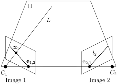
The geometrical interpretation of the epipolar line is the geometric construction in Figure 3.10. The points x1, C1, and C2 define a plane, Π, intersecting the second image plane in the line 1, containing the corresponding point.
From the previous considerations, we have the following pair:
Equation 3.15
![]()
Figure 3.10. The epipolar line.
Observe that
![]()
for every vector v, since
![]()
since eT(e × x) = e · (e × x) = 0. This ambiguity corresponds to the transformation
![]()
We conclude that there are three free parameters in the choice of the second camera matrix when the first is fixed to P1 = [I | 0].
The infinity homography
Consider a plane in the 3D object space, Π, defined by a vector V: VTX = 0 and the following construction; see Figure 3.11. Given a point in the first image, construct the intersection with the optical ray and the plane Π and project to the second image. This procedure gives a homography between points in the first and second images that depends on the chosen plane Π.
Figure 3.11. The homography corresponding to the plane Π.
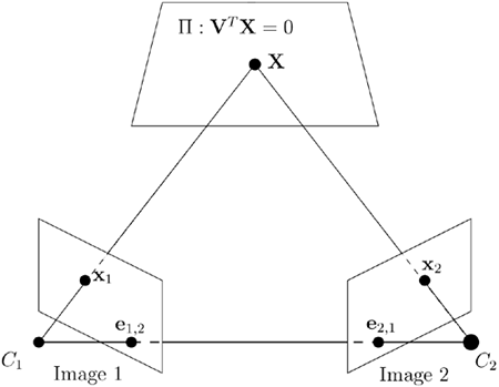
Proposition 8. The homography corresponding to the plane Π : VTX = 0 is given by the matrix
![]()
where e denotes the epipole and V = [v 1]T.
Proof: Assume that
![]()
Write V = [v1 v2 v3 1]T = [v1]T (assuming v4 ≠ 0; that is, the plane is not incident with the origin, or the focal point of the first camera) and X = [X Y Z W]T = [wW]T, which gives
Equation 3.16
![]()
which implies that vTw = – W for points in the plane Π. The first camera equation gives
![]()
x1 ~ [I | 0]X = w,
and using (3.16) gives vTx1 = – W. Finally, the second camera matrix gives
![]()
▪
Observe that when V = (0, 0, 0, 1), that is, v = (0, 0, 0), the plane Π is the plane at infinity.
Definition 29. The homography
![]()
is called the homography corresponding to the plane at infinity or infinity homography. ▪
Note that the epipolar line through the point x2 in the second image can be written as x2 x e, implying
![]()
that is, the epipolar constraint, and we get
![]()
Proposition 9. There is a one-to-one correspondence between planes in 3D, homographies between two views, and factorization of the fundamental matrix as F = HTTe.
Finally, we note that the matrix ![]() is skew symmetric, implying that
is skew symmetric, implying that
Equation 3.17
![]()
3.5.3. Multiview constraints and tensors
Consider one object point, X, and its m images, xi, according to the camera equations λixi = PiX, i = 1 … m. These equations can be written as
Equation 3.18
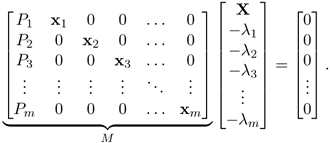
We immediately get the following proposition:
Proposition 10. The matrix, M, in (3.18) is rank deficient; that is,
rank M < m + 4,
which is referred to as the rank condition.
The rank condition implies that all (m + 4) × (m + 4) minors of M are equal to 0. These can be written using Laplace expansions as sums of products of determinants of four rows taken from the first four columns of M and of image coordinates. There are three different categories of such minors depending on the number of rows taken from each image, since one row has to be taken from each image, and then the remaining four rows can be distributed freely. The three different types are:
Taking the two remaining rows from one camera matrix and the two remaining rows from another camera matrix, gives 2-view constraints.
Taking the two remaining rows from one camera matrix, one row from another and one row from a third camera matrix, gives three-view constraints.
Taking one row from each of four different camera matrices, gives four-view constraints.
Observe that the minors of M can be factorized as products of the two-, three-, or four-view constraint and image coordinates in the other images. In order to get a notation that connects to the tensor notation, we use (xl, x2, x3) instead of (x, y, z) for homogeneous image coordinates. We also denote row number i of a camera matrix P by Pi.
The monofocal tensor
Before we proceed to the multiview tensors, we make the following observation:
Proposition 11. The epipole in image 2 from camera 1, e = (el, e2, e3) in homogeneous coordinates, can be written as
Equation 3.19

Proposition 12. The numbers ej constitute a first-order contravariant tensor, where the transformations of the tensor components are related to projective transformations of the image coordinates.
Definition 30. The first-order contravariant tensor, ej, is called the mono-focal tensor.
The bifocal tensor
Considering minors obtained by taking three rows from one image, and three rows from another image:

which gives a bilinear constraint:
Equation 3.20

where
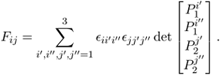
The following proposition follows from (3.20).
Proposition 13. The numbers Fij constitute a second-order covariant tensor.
Here the transformations of the tensor components are related to projective transformations of the image coordinates.
Definition 31. The second-order covariant tensor, Fij, is called the bifocal tensor, and the bilinear constraint in (3.20) is called the bifocal constraint. ▪
Observe that the indices tell us which row to exclude from the corresponding camera matrix when forming the determinant. The geometric interpretation of the bifocal constraint is that corresponding view-lines in two images intersect in 3D; see Figure 3.9. The bifocal tensor can also be used to transfer a point to the corresponding epipolar line (see Figure 3.10), according to ![]() . This transfer can be extended to a homography between epipolar lines in the first view and epipolar lines in the second view according to
. This transfer can be extended to a homography between epipolar lines in the first view and epipolar lines in the second view according to
![]()
since ![]() gives the cross product between the epipole e and the line 12, which gives a point on the epipolar line.
gives the cross product between the epipole e and the line 12, which gives a point on the epipolar line.
The trifocal tensor
The trifocal tensor was originally discovered in the calibrated case in [60] and in the uncalibrated case in [55]. Considering minors obtained by taking three rows from one image, two rows from another image, and two rows from a third image, for example,
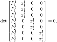
gives a trilinear constraints:
Equation 3.21

where
Equation 3.22

Note that there are in total nine constraints indexed by j" and k" in (3.21).
Proposition 14.
The numbers
![]() constitute a third-order mixed tensor that is covariant in i and contravariant in j and k.
constitute a third-order mixed tensor that is covariant in i and contravariant in j and k.
Definition 32.
The third order mixed tensor, ![]() is called the trifocal tensor, and the trilinear constraint in (3.21) is called the trifocal constraint. ▪
is called the trifocal tensor, and the trilinear constraint in (3.21) is called the trifocal constraint. ▪
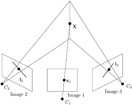
Again, the lower index tells us which row to exclude from the first camera matrix, and the upper indices tell us which rows to include from the second and third camera matrices respectively, and these indices becomes covariant and contravariant respectively. Observe that the order of the images is important, since the first image is treated differently. If the images are permuted, another set of coefficients is obtained. The geometric interpretation of the trifocal constraint is that the view-line in the first image and the planes corresponding to arbitrary lines coincident with the corresponding points in the second and third images (together with the focal points) respectively intersect in 3D; see Figure 3.12. The following theorem is straightforward to prove.
Figure 3.12. Geometrical interpretation of the trifocal constraint.
Theorem 7.
Given three corresponding lines,
11, 12, and
13, in three images, represented by the vectors
![]() and so on, then
and so on, then
Equation 3.23
![]()
From this theorem it is possible to transfer the images of a line seen in two images to a third image, called tensorial transfer. The geometrical interpretation is that two corresponding lines define two planes in 3D that intersect in a line, that can be projected onto the third image. There are also other transfer equations, such as
![]()
with obvious geometrical interpretations.
The quadrifocal tensor
The quadrifocal tensor was independently discovered in several papers, including [64, 26]. Considering minors obtained by taking two rows from each one of four different images gives a quadrilinear constraint,
Equation 3.24

where

Note that there are in total 81 constraints indexed by i", j", k", and l" in (3.24).
Proposition 15. The numbers Qijkl constitute a fourth-order contravariant tensor.
Definition 33. The fourth-order contravariant tensor, Qijkl is called the quadrifocal tensor and the quadrilinear constraint in (3.24), is called the quadrifocal constraint. ▪
Note that there are in total 81 constraints indexed by i", j", k", and l". Again, the upper indices tell us which rows to include from each camera matrix respectively. They become contravariant indices. The geometric interpretation of the quadrifocal constraint is that the four planes corresponding to arbitrary lines coincident with the corresponding points in the images intersect in 3D.
