
Combining resistors and capacitors can
yield some interesting and useful effects. A resistor-capacitor
combination is known as an RC circuit, and they
can take one of three forms. In the first form, the resistor and
capacitor are in parallel (Figure 2-14).
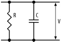
Now, what does this do? A voltage (V) applied across the pair will charge the capacitor (as well as some current flowing down through the resistor). When the applied voltage is removed, the capacitor will discharge through the resistor. The resistor will limit the rate of discharge, since it limits current flow. From Ohm’s Law, we have that:
I = -V / R
(The negative voltage is because we’re discharging the capacitor.) Now, the current flow out of a capacitor is given by:
I = C * dV/dt
So, we have:
dV/dt = -V / RC
Integrating this with respect to time, with zero initial conditions, gives us:
V = e-t/RC
This gives us the discharge waveform shown in Figure 2-15, which represents the voltage across the capacitor.

A parallel RC circuit will provide an exponential decay in the output
voltage. The value for t when the output voltage is at 37% of the
maximum is known as the time constant for the
circuit and is simply the product of R and C:
t = R * C
For example, a parallel RC circuit in which the resistor is 100kΩ and the capacitor is 10μF gives a time constant of 1 second.
The second form of RC circuit is the series RC circuit, shown in Figure 2-16.

When a voltage is applied at the input to the RC circuit (on the left), current will flow through the resistor and the capacitor will begin to charge. However, the resistor limits current flow, and therefore limits the rate at which the capacitor charges.
Now, the current flowing into the capacitor is again given by the relation:
I = C * dV/dt
This current is the same as that flowing through the resistor, and by Ohm’s Law, we have this current given by:
I = (VIN - VOUT) / R
where VIN - VOUT is the voltage drop across the resistor. Combining these two equations gives us the differential equation:
dV/dt = (VIN - VOUT) / RC
Integrating this gives us the voltage at the capacitor as:
VOUT = VIN (1 - e-t/RC)
Again, this is an exponential equation; however, this time, it represents an exponential charging of the capacitor. The waveform for the voltage at the capacitor is shown in Figure 2-17.

In this case, the time constant is the time for the voltage at the capacitor to reach 63% (total -37%) of the input voltage. As before, this time constant is simply the product of R and C.
This form of RC circuit is a simple type of low-pass
filter
. This is a circuit that provides a path
to ground for high-frequency components of a signal, thereby
attenuating them from the main signal, while the low-frequency
components suffer far less attenuation. This type of circuit is very
useful for removing high-frequency noise that may be superimposed on
a signal.
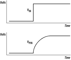
A given processor or peripheral chip will have a small amount of
input capacitance
on each input pin. This, combined
with the small inherent impedance of a circuit connection and the
input impedance of the pin, means that an applied digital voltage to
the pin will actually appear as an exponential rise, rather than a
sharp (digital) edge (Figure 2-18). These effects
are minimal, but can be significant in high-speed circuits or when
several devices are connected to the same signal line and the overall
input capacitance is not insignificant.
The effect of lead inductance can contribute second-order characteristics, such as those shown in Figure 2-19. These inductive effects create “ringing” when a sudden voltage change is applied. Inductors will be discussed shortly.

The third form of an RC circuit is shown in Figure 2-20.

This type of circuit is a simple form of a high-pass
filter
, since it passes only the high
frequencies through to the output. The capacitor in such a circuit is
known as a blocking
capacitor
.