
Never let the future disturb you. You will meet it, if you have to, with the same weapons of reason that today arm you against the present.
No town or freeman shall be compelled to build bridges . . . except those with an ancient obligation to do so.
In this chapter, we’ll look at connecting your embedded computer to the real world by adding a Local Area Network (LAN) interface. Of the wide variety of networks employed, some are very common, some not so common. We’ll take a look at RS-485, CAN, and Ethernet.
RS-485, a simple network used for connecting small controllers, is very low in cost and simple to implement. CAN is a network for industrial applications in which a conventional network just won’t do. CAN is suited to electrically noisy and harsh conditions and is the network of choice in electrically severe environments. Ethernet is the intranet network that connects the world’s desktop computers, as well as a host of other devices such as routers, gateways, printers, and other peripherals.
RS-485 is a variation on RS-422 (Chapter 10) used for low-cost networking and is commonly used in many industrial applications. It is one of the simplest and easiest networks to implement. It allows multiple systems (nodes) to exchange data over a single twisted pair (Figure 11-1).
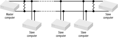
RS-485 is based on a master/slave architecture. All transactions are initiated by the master, and a slave will transmit only when specifically instructed to do so. Many different protocols run over RS-485, and often people will do their own thing and create their protocol specific to the application at hand.
The interface to the RS-485 network is provided by a transceiver, such as a Maxim MAX3483 (Figure 11-2).
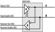
It is simply an RS-422 transceiver with enable inputs; using it in a design is straightforward. On the network side, the MAX3483 has two signal lines, A and B. This is the twisted-pair (network cable) attachment point. The MAX3483 also has Data In (DI) and Receiver Out (RO). These are connected to the Tx and Rx signals of the UART (or microcontroller), respectively.
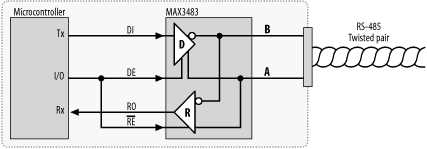
Since it is connected to a common network upon which it must both listen and transmit, it has two control inputs, Data Enable (DE) and Receiver Enable ( RE ). A high input to DE allows the DI input to be transmitted on the network. A low input to DE disables the output of the transmitter. Similarly, a low input to RE enables the receiver, and network traffic is passed through to RO. DE and RE are normally controlled by an I/O line of the processor. Now, you’ll notice that DE is high active and RE is low active. This is not by chance. A node on the network won’t be receiving traffic if it’s transmitting and, conversely, won’t be transmitting if it is receiving. Therefore, only either the transmitter or the receiver should be active at any one time. If the transmitter is on, the receiver should be off, and vice versa. The control for the transmitter is therefore the logical opposite of the control for the receiver. By having DE high active and RE low active, a single control line may be used for both. Figure 11-3 shows a MAX3483 interfaced to a microcontroller in this way. The microcontroller normally has DE/ RE low so that it is listening to network traffic. When it wishes to transmit, it sends DE/ RE high. Upon completion of transmission, it returns DE/ RE low and resumes listening.
RS-485 may be implemented as half duplex, in
which a single twisted pair serves for both transmission and
reception (Figure 11-4), or full
duplex, in which separate twisted pairs are used for each
direction (Figure 11-5). Full duplex RS-485 is
sometimes known as four-wire mode. Note that for full duplex
operation, the MAX3483s are replaced with MAX3491s that have dual
network interfaces.
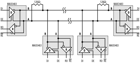
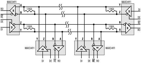
The two figures show four computers (nodes) connected to an RS-485 network. Each RS-485 interface chip (MAX3483 or MAX3491) exists in a separate embedded computer. The UART transmitter output, Tx, in each embedded system is connected to the respective DI (Driver In) of each of the RS-485 interface chips. Similarly, RO (Receiver Out) connects to the Rx input of each UART. The driver of each RS-485 interface chip is enabled by asserting DE (Driver Enable), and similarly, reception is enabled by asserting RE (Receive Enable).
Normally, all systems connected to the RS-485 network have their receivers enabled and listen to the traffic. Only when a system wishes to transmit does it enable its driver. A number of formal protocols use RS-485 as a transmission medium, as do twice as many homespun protocols. The main problem you need to avoid is the possibility of two nodes of the network transmitting at the same time. The simplest technique is to designate one node as a master node and the others as slaves. Only the master may initiate a transmission on the network, and a slave may respond directly only to the master, once that master has finished.
The number of nodes possible on the network is limited by the driving capability of the interface chips. Normally, this limit is 32 nodes per network, but some chips can support up to 512 nodes.