
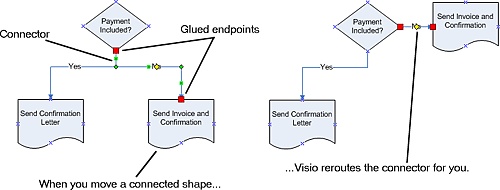
Many types of Microsoft Office Visio diagrams depict related ideas, relationships, or sequences by showing shapes that are connected with lines. For example, a flowchart shows each of the steps in a process as a series of shapes connected by lines. Organization charts show employee relationships as a hierarchy of shapes connected by lines. Network diagrams use lines to show equipment connected to hubs. Visio makes it easy to connect the shapes in these diagrams by using connectors —1-D shapes (usually lines or arrows) that connect 2-D shapes, such as the process shapes in a flowchart. If you rearrange the connected 2-D shapes, the connectors stay attached to the shapes and are rerouted for you, so you don't waste time redrawing lines. In some diagrams, such as flowcharts, you can even drag a 2-D shape between two connected shapes, and Visio reroutes the connector and connects all three shapes.
This chapter shows you how to connect shapes and work with connectors in a flowchart. However, the techniques that you use to connect flowchart shapes apply to other types of diagrams as well. As you modify shape connections and arrange connected shapes, you can take advantage of several layout tools that help you evenly distribute, align, and position shapes. You can even change the orientation of all the connected shapes in a diagram; for example, you can change the layout in a flowchart from top to bottom and from left to right.
See Also
Do you need only a quick refresher on the topics in this chapter? See the Quick Reference entries. in Quick Reference
Important
Before you can use the practice files in this chapter, you need to install them from the book's companion CD to their default location. See "Using the Book's CD" for more information.
Flowcharts are the ideal diagrams for visually representing business processes. For example, if you need to show the flow of a custom-order process through various departments within your organization, you can use a flowchart. Visio includes several different flowchart templates; however, the most common type of flowchart uses simple shapes to represent the basic elements in a business process, as shown in the following table.
Shape Name | Shape | What It Represents |
|---|---|---|
Process | Steps in a business process | |
Decision | Decisions in a business process | |
Document | Steps that result in or require documentation | |
Data | Steps that require data |
You add connectors between these flowchart shapes to show relationships between them and the sequence of steps in a process. Flowchart connectors are usually lines with arrowheads that can include text to clarify the process being depicted. When you draw a connector (or when Visio draws it for you), the endpoints of the connector glue to the shapes—that is, Visio creates a bond that won't break unless you move a connector endpoint or delete the connector. When you select a connector that is glued to a shape, the connector's endpoints turn red, indicating that the connector will be rerouted when you move the connected shapes.
There are several methods of connecting shapes. For flowchart shapes, it's best to use the Connector tool, which you access by clicking the Connector Tool button on the Standard toolbar. You can connect shapes with the Connector tool in two ways:
You can add shapes to the drawing page first, and then use the Connector tool to draw connectors between shapes.
You can use the Connector tool to drag shapes from a stencil onto the drawing page so that each shape you drag is connected to the selected shape on the page. Visio draws the connectors for you.
Important
To connect shapes as you drag them onto the drawing page, make sure you select the Connector tool before you drag the shapes onto the drawing page.
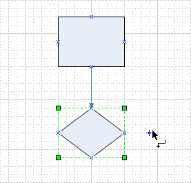
As you drag a flowchart shape onto the drawing page, a dynamic grid appears as a dotted line through the shape to show you how to align it with respect to the shapes already on the page.
In this exercise, you start a new diagram based on the Basic Flowchart template. You drag several shapes onto the drawing page using the Connector tool so that Visio draws the connector and connects the shapes for you. You add text to the connectors to indicate a yes or no decision. Then you draw your own connector between two shapes using the Connector tool.
Start Visio. In the Choose Drawing Type window, in the Category area, click Flowchart. In the Template area, click Basic Flowchart.
The Basic Flowchart template opens a blank drawing page and the Basic Flowchart Shapes, Backgrounds, Arrow Shapes, and Borders and Titles stencils.
On the Standard toolbar, click the Connector Tool button.
The pointer displays a connector icon.
From the Basic Flowchart Shapes stencil, drag a Process shape onto the drawing page and position it near the top of the page.
From the Basic Flowchart Shapes stencil, drag a Decision shape onto the drawing page and position it below the Process shape.
Visio draws a connector between the shapes. The connector has an arrowhead at its end point, which is the default connector style for the Basic Flowchart template.
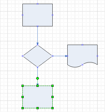
From the Basic Flowchart Shapes stencil, drag a Document shape onto the drawing page and position it to the right of the diamond-shaped Decision shape.
Visio draws a connector between the Decision and Document shapes.
Click the Decision shape to select it.
From the Basic Flowchart Shapes stencil, drag another Process shape onto the drawing page and position it below the Decision shape.
Visio draws a connector between the Decision and Process shapes.
On the Standard toolbar, click the Pointer Tool button.
Click the top Process shape to select it.
Hold down
 and left-click the top Process shape to zoom in on it.
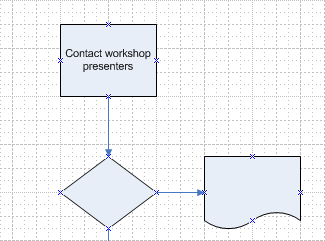
With the top Process shape selected, type Contact workshop presenters.
The text is added to the shape.
Select the Decision shape, and type Presenter available?
Select the Document shape, and type Send presenter kit and contract.
Select the bottom Process shape, and type Contact exhibitors.
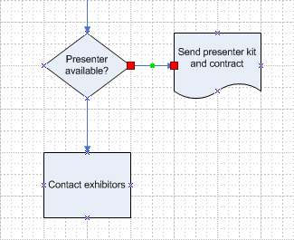
Click the connector between the Decision shape and the Document shape to select it.
The connector's endpoints turn red, indicating that the connector is glued to the shapes and will be rerouted when you move the connected shapes.
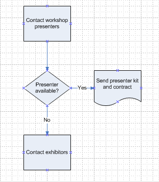
With the connector selected, type Yes.
The text is added to the connector.
Select the connector between the Decision shape and the bottom Process shape, and then type No.
The text is added to the connector.
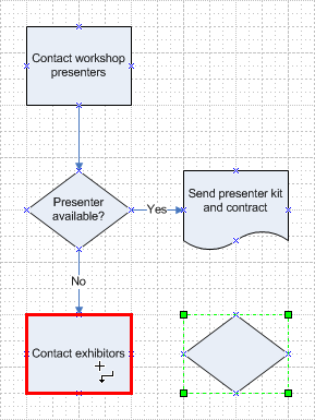
Click the pasteboard to deselect the shape.
From the Basic Flowchart Shapes stencil, drag a Decision shape onto the drawing page and position it below the Send presenter kit and contract shape.
On the Standard toolbar, click the Connector Tool button.
The pointer displays a connector icon.
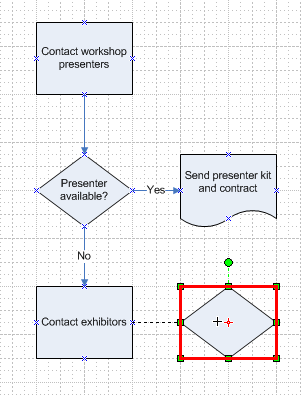
Position the pointer over the Contact exhibitors shape.
A red border appears around the shape.
Drag to the Decision shape on the right until a red border appears around the Decision shape.
Release the mouse button.
Visio draws a connector between the two shapes.
With the connector selected, type Yes.
On the Standard toolbar, click the Pointer Tool button.
Select the Decision shape, and then type Exhibitor available?.
Click the pasteboard to deselect the shape.
On the File menu, click Save As to open the Save As dialog box.
In the File name box, type ConnectFlowchart, and then click the Save button to save the flowchart.
CLOSE the ConnectFlowchart file.