
Chapter 10. Levels of Detail (LODs)
CD Files
Kila_Texture.mb
Kila_Pose.mb
Kila_LOD_Prep.mb
Kila_LOD_Active.mb
Grae_Texture.mb
Grae_Pose.mb
Grae_LOD_Prep.mb
Grae_LOD_Active.mb
KilaBody.tga
KilaHair.tga
KilaHead.tga
GraeBody.tga
GraeBody_Bump.tga
GraeBody_Spec.tga
GraeMisc.tga
GraeMisc_Bump.tga
GraeMisc_Spec.tga
GraeWing.tga
Now that our characters are complete, including textures, and have been signed off by our managers, we can proceed to generate the level of detail (LOD) models needed to preserve processing power.
As we have already discussed (mainly in Chapter 5, “Model Optimization”), saving processor power and memory is very important when creating computer games. Here in Chapter 10 we will demonstrate how to gradually reduce a character to its lowest resolution, efficiently optimizing the model to get the various levels of detail needed in the game.
Why Do We Need LODs?
When a character is far off in the distance, essentially taking up few pixels on the screen, there is no need for the character to have 4000 polygons when 100 or less will do.
This is where LODs come into play. What you do is take your main model and create four versions, or five, or however many are needed, each one stepping down in its polygon count. As the character moves away from the camera, a different version of the model is loaded in its place. The farther away from the camera, the lower the version, until the character can no longer be seen.
If we use Kila as an example, her main model of 4094 polygons would more than likely be used for close-up shots, or maybe just in cut scenes. The next LOD for Kila, then, would be the main one used in game, since we could remove around 1000 polygons and still retain all the detail needed. The LOD after that would comprise 1000 polygons; then we’d drop down to around 500; and the last one would be about 100 or 200. As you can see, we step down gradually at first, before dropping dramatically as distance from the character increases. We can do this because there will be decreasing need for detail as the character moves farther away.
Tip
The graphics programmer usually sets the number of LODs and the number of polygons in each LOD. The trick is to have as few LODs as possible. One rule of thumb in the industry is “The sum polycount of all LODs shouldn’t exceed the main game model.”
You can see Kila with her levels of detail in Figure 10.1. Although there are fewer polygons in the versions that are farther away, you cannot tell.
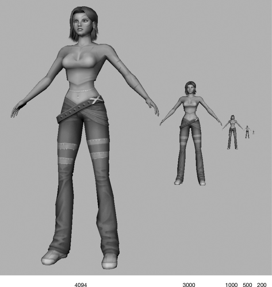
Check out the games you play. Look carefully, and you will see characters or objects “pop” as they move away from the camera. This is the game engine swapping the current model for a lower LOD.
Setting the Binding Pose
Before we proceed to create LODs for both our characters, we need to alter their pose. We began with both Kila and Grae in the basic T pose, which made it easier to work with them, but we will need to alter the pose in preparation for the characters to be bound to a skeleton (which we’ll do in the next chapter).
It’s advisable to alter the pose now (you could even start off designing your models with the arms posed like this, to save time). Otherwise, once the level of detail models have been created, you would need to edit five models instead of just one.
The main areas that will need altering on Kila are the arm and finger positions.
Arm Adjustment
The arm should be at the average position between the most-used extreme positions. If a character only ever walks with its arms down by its sides, it doesn’t make any sense to raise the arms up to shoulder level when you bind it. This would just increase distortion to the shoulder area when the skeleton deforms the mesh.
Kila will be performing generally ordinary actions, so the arms should be set at about a 45 degree angle.
Before we adjust them, we need to make the arms separate objects so that they’re easier to manipulate.
Detach the Arms
Not only do we need for the arms to be detached from the torso, but also to be separated along their UV borders so that we keep the UV’s intact.
Open up the file called Kila_Texture.mb.
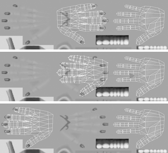
1. Select the main body geometry and open the UV Texture Editor (Figure 10.2, left). Because we combined the body geometry, all the UVs are being displayed on top of each other. We need to separate the UVs in order to see the ones belonging to the arms.
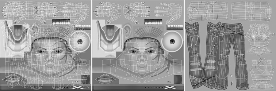
2. You can tell Maya to show only the faces belonging to the background image, by going to View > View Faces Of Selected Images. As seen in Figure 10.2 (middle), this will hide the other UVs not associated with this texture page.
It may be that the incorrect image is displayed in the background, giving you the wrong UVs (Figure 10.2, left). To switch to the image you need, select it from the Image > Selected Images menu.
3. Select the faces belonging to the arms, and return to the main view panel.
4. Using the Extract tool, separate the arms from the body as seen in Figure 10.3.
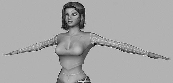
The arms are now free for you to work on. (Notice your bonus: The hands are now separated, too, ready for LOD work later.) Next we will look into the best approach for rotating the arms.
Rotate the Arms
We want to rotate both the arms the same amount and from the same pivot on either side. We could adjust the pivot as shown earlier in the book, snapping it to a vertex close to where our shoulder pivot would be. This wouldn’t be very accurate, though, because the arm would rotate around the wrong axis. What we want is for the axis to follow the orientation of the arm.
For this purpose we will use a locator, which is a very simple dummy object that takes the shape of a cross. Locators have many uses: They can pinpoint positions in space; they can be used as a main controller; or, as in this case, they can be used to drive the rotation of a series of objects.
We will position a locator where the shoulder pivot is, and parent the arm and hand to it. When the locator is rotated, the arm will rotate correctly.
1. Create a locator by going to Create > Locator. Then move it up to the correct position over the shoulder’s pivot point (Figure 10.4a).
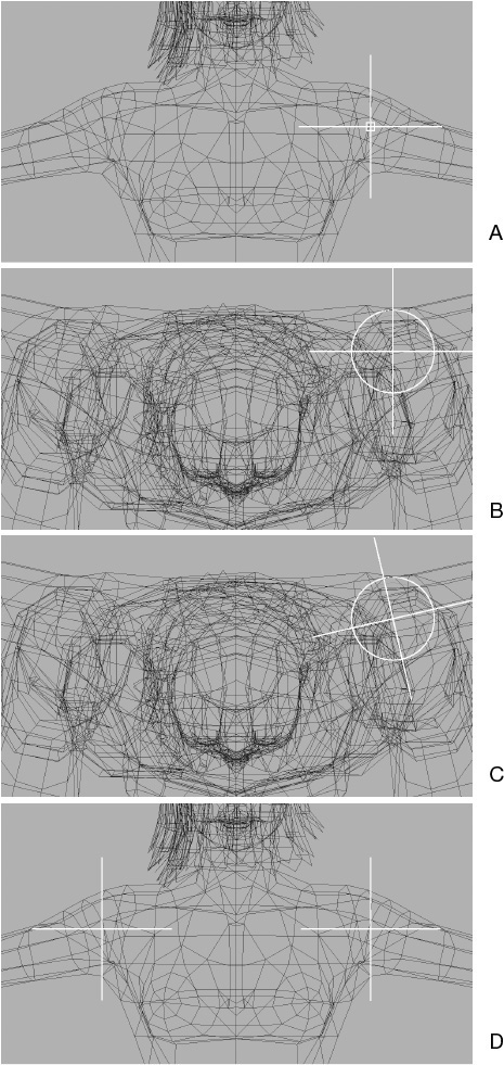
2. To make the rotation more precise, switch to the top view (Figure 10.4b) and rotate the locator to match the orientation of the arm (Figure 10.4c). This rotation should only be around the Y axis.
3. Duplicate the locator, and make the Translate X and Rotate Y attributes negative values. This mirrors the locator for the other arm (Figure 10.4d).
4. Now select the arm geometry for the first arm, then the hand, and then the locator last. To parent them, press P.
Do the same for the opposite arm, parenting the arm and hand to the other locator.
Note
By selecting the locator last, you are telling Maya that you want the objects you selected first to be parented to the locator.
5. The rotations must be exactly the same on either side, so we will activate snapping on the Rotate tool. Double-click the Rotate tool icon, opening up the tool’s options (Figure 10.5).
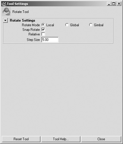
Enable Snap Rotate and set the Step Size to 5.0. This will make the tool rotate in units of 5 instead of flowing freely.
6. Rotate the locator around the Z axis (blue), using the manipulator and not the Channel Box. (If you used the Channel Box, the locator would not rotate around its local axis; instead, the Z axis might default back to the global axis.)
Rotate the locator by seven steps, and then do the same to the opposite arm (Figure 10.6).
The arms are now orientated correctly, meaning we can now reattach them to the torso. Make sure you deactivate Snap Rotate on the Rotate tool before you proceed.
Reattach the Arms
Now the two arms are in position, and we can stitch them back onto the torso. First, we need to combine the three pieces of geometry into a single model.
1. Select both arms and the torso and combine them (Polygons > Combine).
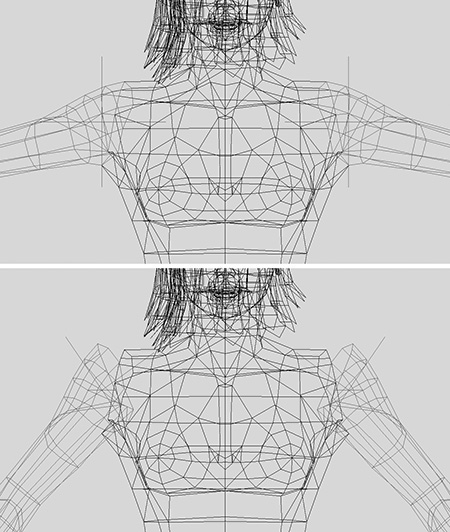
2. Work your way around the shoulders, merging the vertices so that they lie in between the arm and torso geometry (Figure 10.7, right).
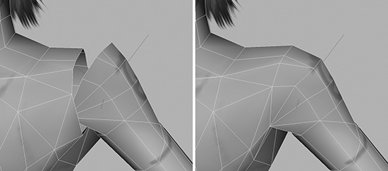
3. As you can see in Figure 10.8, left, the shoulders are no longer shaped correctly, so work the vertices and smooth out both shoulders (Figure 10.8, right).
Tip
Remember—to keep the shoulders symmetrical, select the opposing vertices and move them at the same time. If the vertices need to be moved away from or toward each other, simply use the Scale tool instead of translation.
Now that the shoulders are repositioned and smoothed out, let’s reposition the fingers.
Finger Adjustment
Like the arms, the fingers should be between their most extreme positions. Currently they are flat, which is close to one extreme. We need to go in and bend them slightly so that they look more relaxed.
Note
Adjusting the hands is a good idea, but it’s not strictly necessary, so feel free to skip this section if you like.
To save time, we can delete the right hand and work only on the left. We can do this because both hands have more or less the same UV mapping. Then we can duplicate the edited hand to replace the right hand.
1. Delete the right hand.
2. The left hand will still be parented to the locator, so unparent it by selecting it and going to Edit > Unparent.
The hand’s orientation is currently correct, but to make editing the fingers easier, you’ll need to rotate the hand in order to flatten it. Before you do, though, you need to store (freeze) its current position and rotation.
3. Freeze the transforms (Modify > Freeze Transforms). This will reset the translation, rotation, and scale values to zero, meaning that after you’re done editing the fingers, you can just set the Rotate values back to zero again, resetting the hand to its correct position.
4. When you detached the arm at the very beginning of this pose-adjustment process, the pivot point for the hand defaulted back to the center of the world, and this will now make it difficult to manipulate. So center the pivot for the hand by going to Modify > Center Pivot.
5. With the translation, rotation, and scale values at zero and the pivot centered, you can now rotate the hand so it is flat, as shown in Figure 10.9, middle.
6. Adjust the fingers so they are like the ones in Figure 10.9, right, bending them into a more relaxed pose. Look at your own hand for reference.
7. When you are happy with the shape of the fingers, reset the hand rotations back to zero in the Channel Box or by using the Modify > Reset Transforms tool, returning the hand back to its correct orientation.
8. Duplicate the left hand to create the right hand.
Note
Make sure you snap the pivot point back to the world’s center before you mirror it. Press Insert to activate the pivot point and then hold down X, which will snap the point to the grid as you move it.
9. With the right hand selected, open the UV Texture Editor and adjust the UV’s so the back of the hand is over the section that does not have the tattoo on it. You can see this in Figure 10.10.
10. To finish your work on the pose, clean up all the geometry in the scene. Go to Edit > Delete All By Type > History. You have to delete the history first because (even though none of the geometry is still parented to the locators) the locators are still attached to the geometry via history. Once the history is cleared, you can safely delete the locators.
11. Finally, save the scene as Kila_Pose.mb.
Tip
Now that you have a hand that is modeled, optimized, textured, and posed, I recommend saving it to your Morgue. It’s a nice addition to your collection for use on future characters.
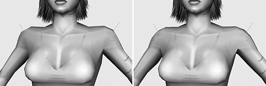
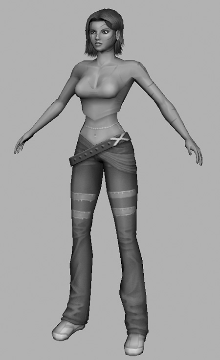
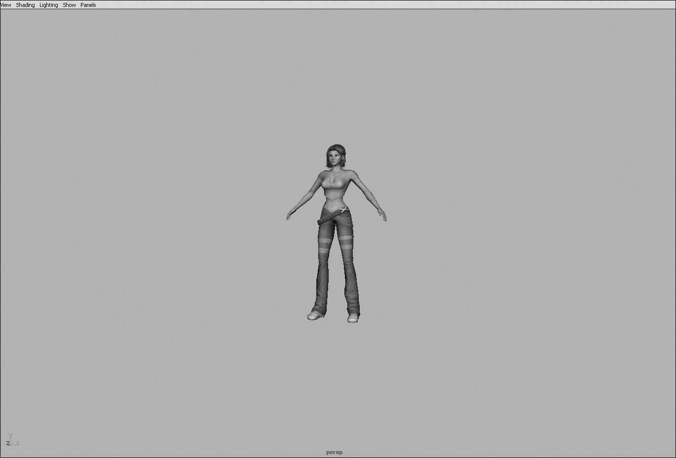
Figure 10.11 shows Kila in her new pose.
Grae, too, needs to be posed, so load Grae_Texture.mb. Adjust his arms and fingers just as you have done Kila’s. Save him as Grae_Pose.mb when he’s finished.
When your models are posed and ready, you can begin generating the levels of detail.
Generating LODs
Creating the LODs is in some ways similar to optimizing the mesh. There are two principal stages:
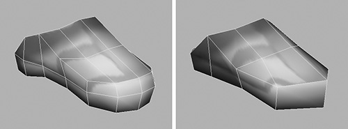
![]() First, look for areas that can be sacrificed, or in this case, what can’t be seen when the camera is at that particular distance. For example, if the individual fingers are not visible when you zoom out, you can combine the fingers to create a mitten-type hand.
First, look for areas that can be sacrificed, or in this case, what can’t be seen when the camera is at that particular distance. For example, if the individual fingers are not visible when you zoom out, you can combine the fingers to create a mitten-type hand.
![]() After you have removed any unnecessary detail, you can remove more polygons. Look for areas that create shallow angles and places that house unused polygons, just as you do in optimization. Continue to do this until you reach the polygon limit of the LOD you are creating.
After you have removed any unnecessary detail, you can remove more polygons. Look for areas that create shallow angles and places that house unused polygons, just as you do in optimization. Continue to do this until you reach the polygon limit of the LOD you are creating.
Kila is currently made up from 4094 polygons. This will be the first LOD and the main model that will be used for close-ups. It’s more than likely the next LOD will be the one mostly viewed in game. So let’s create four more levels of detail for her at the following polygon counts: 3000, 1000, 500, and 150.
LOD 2: 3000 Polygons
Make sure the Kila_Pose.mb file is open. Before creating the second LOD, we must duplicate the current character’s geometry. We only need one copy at this stage, because the LOD after this one will be based on this LOD 2’s complete geometry.
1. You should have all the pieces of the character in a group called Kila. Rename this to Kila4094.
2. Duplicate this group, calling the new copy Kila3000.
3. Create two new display layers (go to Layer > Create Layer in the Layer Editor), one for each separate version of the model. Call one Kila_4096 and the other Kila_3000, placing the appropriate group into each layer.
4. Hide the original file (Kila4094) by turning off the layer’s visibility, so you are only working with the duplicate.
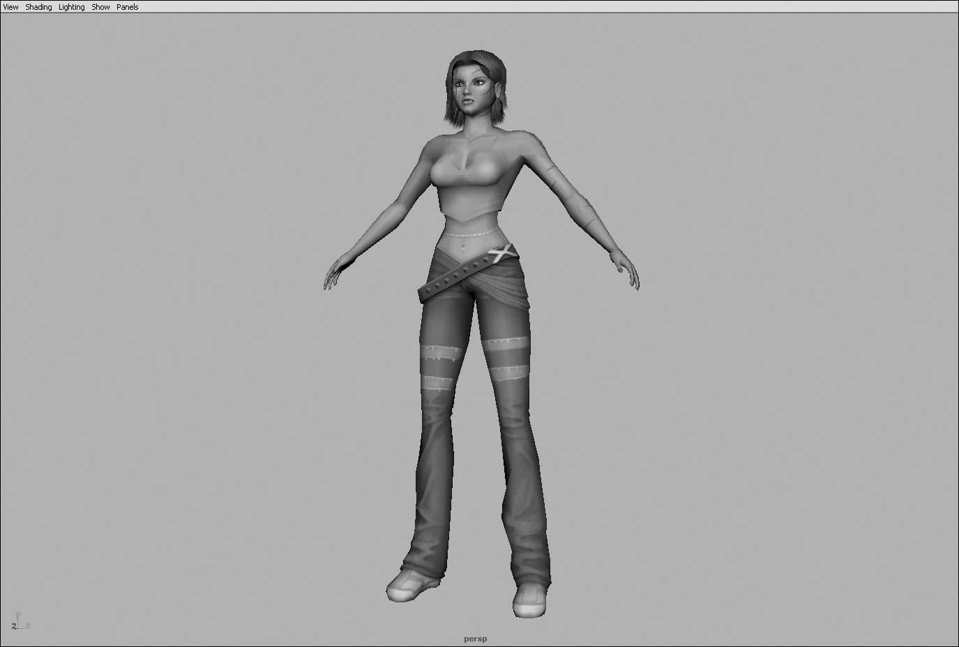
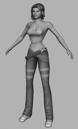
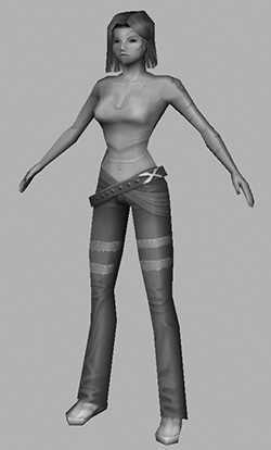
5. Position the model (by just moving the camera) as seen in Figure 10.12. She should more or less fill the screen; this will be the size of the full-resolution character.
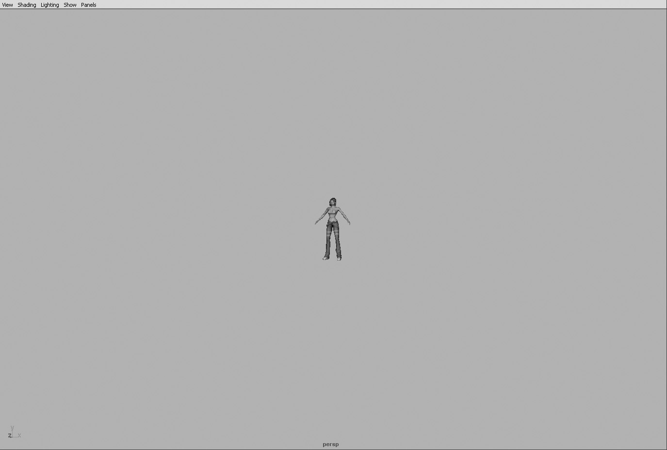
6. Now dolly out until she is roughly half-size (Figure 10.13). This is approximately the distance at which this model will be viewed when in a game. When the main model is this far away from the camera, the game will switch to this LOD.
7. Now that you have a basic distance to gauge your model on, begin rotating around her and see what you can initially sacrifice. At this distance you can still see quite a bit of detail; even her individual fingers are still visible. What you can do, though, is
![]() Remove the highlights created for her eyes, and delete her eyelashes and her tongue. (If she does talk at this distance, you will not see it.)
Remove the highlights created for her eyes, and delete her eyelashes and her tongue. (If she does talk at this distance, you will not see it.)
![]() Remove the single strand of hair from the front of her head, as well as the first inside layer of her hair. After doing this, you will need to tweak the remaining inner layers of hair to fill the gap that now exists.
Remove the single strand of hair from the front of her head, as well as the first inside layer of her hair. After doing this, you will need to tweak the remaining inner layers of hair to fill the gap that now exists.
That’s about as much as you can remove at this stage, but she is still using 3878 polygons. Next we will go in and remove some areas of small detail in order to get closer to our 3000 limit for this LOD.
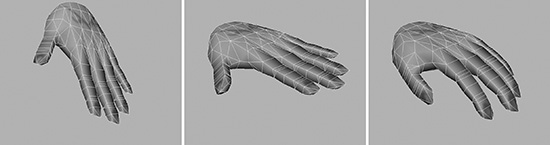
Hands
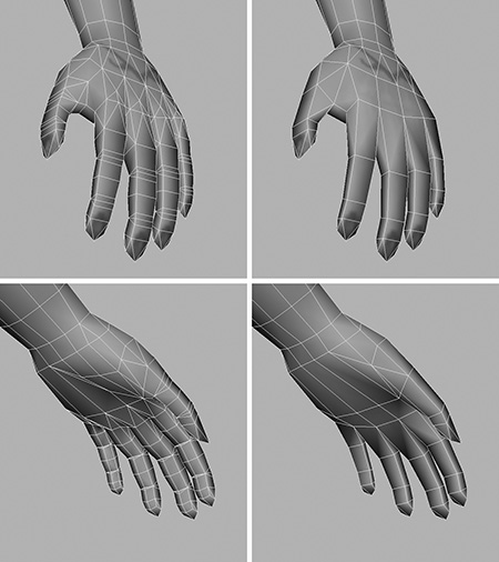
Although Kila’s fingers are still visible at this level, they don’t need to have much detail in them; it’s sufficient if they merely “suggest” fingers. In designing the main hand, we included polygons around the joints so that the fingers would not pinch badly when bent. There is no need for these polygons at this distance, so we can remove them.
Reduce the fingers down to basic cubes like the ones seen in Figure 10.14, right. If you are merely merging vertices or collapsing edges, the UV information should stay intact.
Reducing the fingers brings us down to 3236 polygons, not too far from our goal.
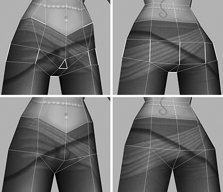
Sash and Jeans Legs
Let’s now reduce some areas of detail in the sash and the jeans legs, which won’t be missed at this distance. When creating the main model, we built creases on her hip to give the sash additional detail, and creases and folds in the jeans. This detail can now be removed.
1. Begin by collapsing the main edges that create the overhang for the folds of the sash. These are highlighted in Figure 10.15a.
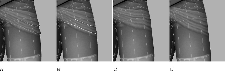
2. Remove the final set of edges that made up the folds (Figure 10.15b).
3. As you can see in Figure 10.15c, the UVs have been altered. So, open up the UV Texture Editor and fix the UVs using the main model (Kila_4096) as reference (Figure 10.15d).
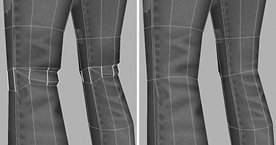
4. Remove the similar folds in the jeans at the back of her knees. Do this by collapsing the edges highlighted in Figure 10.16.
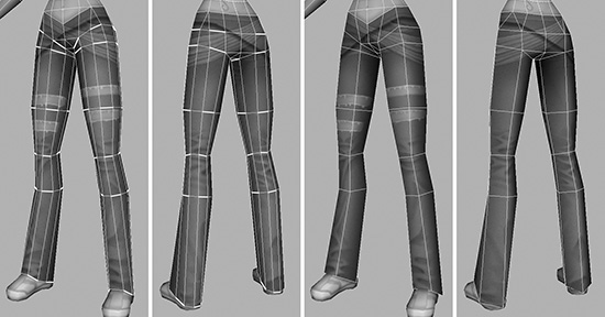
5. Now focus on the folds at the base of her legs. Work your way around these, collapsing the majority of the edges until you have a more rudimentary-looking lower leg (Figure 10.17, right).
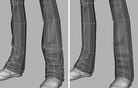
With these reductions to the sash and jeans, our polygon count now stands at 2948, just under the limit. This is great news—it means we can move on and begin work on the next LOD.
Before you do, rename the group and the display layer to represent the new polygon count. So Kila3000 would become Kila2948, and Kila_3000 would be Kila_2948. This helps to inform others of the polygon count and keeps you up to date.
Figure 10.18 shows our second level of detail. You shouldn’t see much of a difference in Kila’s form at present, which is good because this model won’t be too far away from the camera.
LOD 3: 1000 Polygons
LOD 3 will be quite a dramatic step down because we will be able to remove a huge amount of polygons from areas where they are not seen at this distance.
1. Create the base geometry to work on. Duplicate the previous LOD’s group (Kila2948) and call the new copy Kila1000.
2. Create a new display layer called Kila_1000, placing into it the Kila1000 group and its contents.
3. Turn off the visibility for the layer called Kila_2948. This leaves you with just the new geometry to work on.
4. As you did before, zoom out to about half the size of LOD 2 to get an idea of how the geometry will be viewed in a game. You can see this in Figure 10.19. From this distance, you can’t see very much detail. Her facial features are lost, as are her fingers. It should be quite easy to reduce this version down to 1000 polygons.
Note
We could even go lower than 1000 for LOD 3. Just because we have a limit doesn’t mean we must hit it exactly; we just can’t go over it. If areas are not seen, then there is no use for them, so we may as well delete them.
5. Let’s first remove obvious things that can’t be seen. This version of the model will not have any facial animation because you simply won’t be able to see it, so you can remove the inner mouth, including the teeth, and weld her lips together.
6. Remove her eyes and her ear; they won’t be seen, either.
7. Both inner layers of her hair can go, too. We can adjust the outer layer to compensate for this loss.
With these elements removed, we are down to 2692, so let’s zoom in and begin reducing the main geometry.
Hair Reduction
Begin by working on her hair.
1. Focus on her hair geometry by selecting it and pressing F.
2. Select the edges shown in Figure 10.20 (left) and then collapse them (Figure 10.20, right).
3. Delete the triangular faces at the very bottom of the hair and then weld the separate strips together, making the mesh solid.
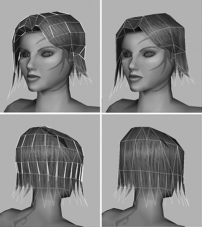
4. Optimize the hair further, removing polygons not only from the outside, but from the fringe of hair at the forehead (Figure 10.21, left).
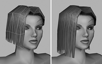
5. Extend the hair down to roughly match its original length on the higher-resolution model (Figure 10.21, right). It doesn’t have to be exact; we can edit it more precisely in the next step.
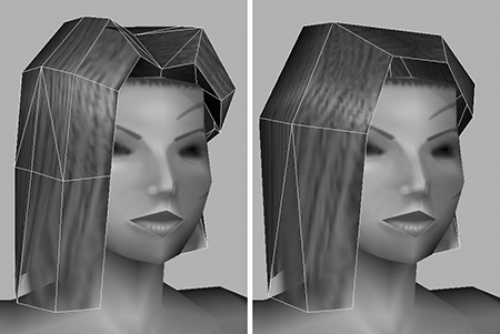
6. Because we have removed polygons, the overall shape of the hair will be less full. Make the LOD 2’s display layer visible, turning the display type to Template. This will show the second LOD’s geometry as a gray wireframe over the current model (Figure 10.22, left).
7. You can now work on the hair, shaping it as seen in Figure 10.22, right, “thickening” it to match its previous look.
We will leave the hair as it is for now; this should be sufficiently reduced. Next we will trim down her face.
Face Reduction
We only really need to keep basic features in the face. Take another look at Figure 10.19; you can’t see any major details.
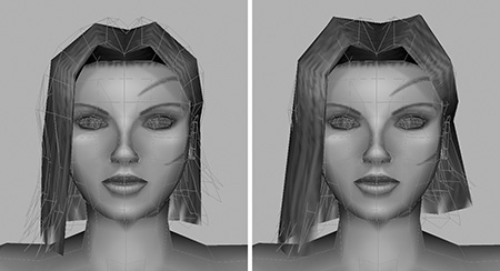
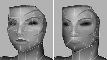
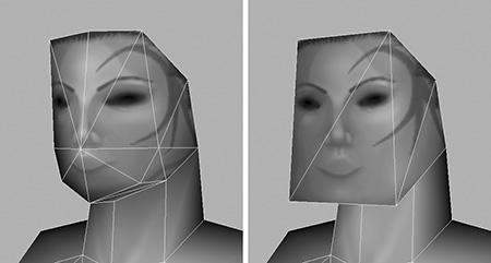
1. Focus in on the face. Feel free to hide the hair at this stage, to make working on the head easier. Then, as demonstrated in Figure 10.23 (top-right), weld the eyes closed.
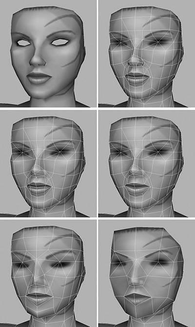
2. By now you should have a good grasp of polygonal modeling, so go ahead and work on the nose and then the lips (Figure 10.23, middle). Finally, work your way around the face, collapsing edges there until you have a basic face like the one in Figure 10.23, bottom-right.
Note
Remember to keep updating the UVs as you work, as well as checking the shape against the next-higher LOD.
Don’t worry too much about deciding where to remove faces. Once you start collapsing edges, you will notice other areas that can be collapsed. They will stand out because the detail in that area does not match where you are currently working.
The model is starting to look quite odd now, but remember that this version will only ever be seen from a distance. Keep zooming out as you work, to get a realistic idea of how she will look in a game.
You will probably have the urge to continue reducing polygons on her neck and the rest of her body, mainly because the head and body don’t match anymore. But wait; we will look at the rest of the body later on. Next up are the hands.
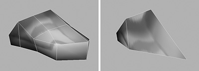
Hand Reduction
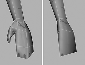
The hands have far too much detail in them for this level. We no longer require separate fingers, for example, so we will convert them into flat, mitten-style hands as mentioned earlier.
1. Begin by welding the fingers together as seen in Figure 10.24b, making sure you delete the inner faces afterward.
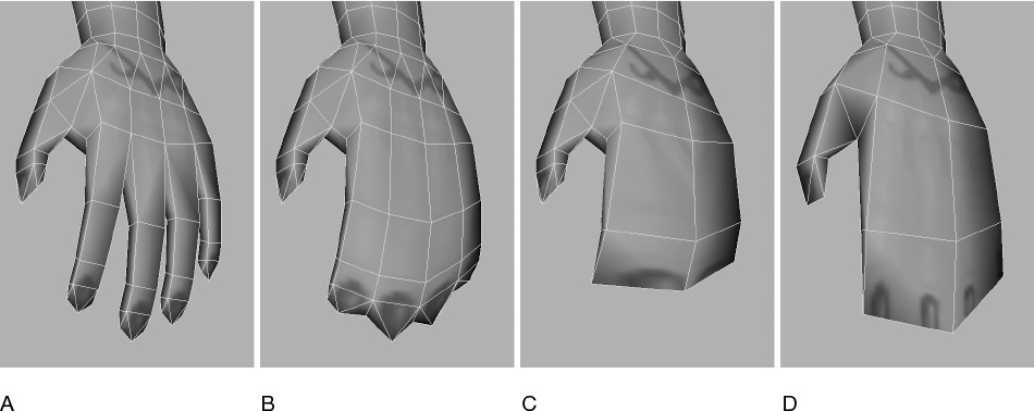
2. Remove the finger ends, flattening out the end of the hand (Figure 10.24c).
3. Work on the whole hand, reducing the overall detail, and remember to fix the UVs afterward.
You should now have a low-polygon mitten-type hand like the one shown in Figure 10.24d.
The reduced hands can now be used to guide optimization of the arms.
Limbs Reduction
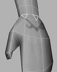
Because we reduced the hands, triangles will have appeared at the wrist area (Figure 10.25). This is because the sections there no longer match up to the ones where the hands attach to the arms.
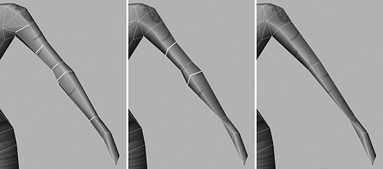
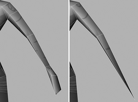
1. On each arm, follow the triangles, and select the edges all the way up Kila’s arm. You should end up with each alternate strip selected (Figure 10.26, left).
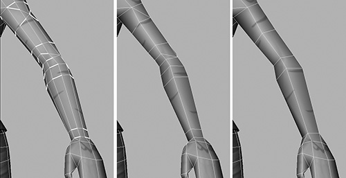
2. As you can see in Figure 10.26 (middle), collapsing these edges will reduce the arm from having ten divisions around the axis to five.
3. Optimize each arm further (Figure 10.26, right), removing most of the detail we added to allow it to deform correctly. At this camera distance, you won’t be able to tell whether the elbow and wrist look wrong as they bend.
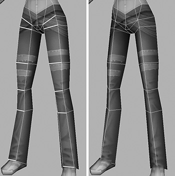
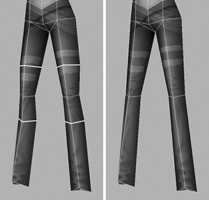
4. Now take a look at the legs. Remove most of the detail highlighted in Figure 10.27, left, following the polygons around to her buttocks. This will leave the legs in a more or less cylindrical shape.
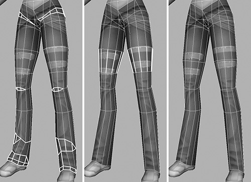
5. We have a shallow angle on the thigh area. Select the edges shown in Figure 10.27, middle, and collapse them. The legs will look like those in Figure 10.27, right.
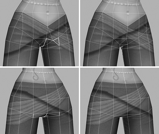
6. In the crotch and buttock area, remove the polygons shown in Figure 10.28.
7. Now repeat for the legs the steps used when you reduced the arms. Select the edges that make up every second vertical strip (Figure 10.29, left) and collapse them, reducing the divisions around the legs from ten to five.
The legs are now sufficiently reduced. Remember to use LOD 2 as a template to fill them out, since they will have thinned down when the edges were collapsed.
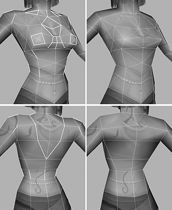
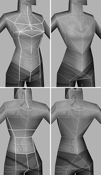
Torso Reduction
Compared to the rest of the model, the torso now looks out of character; it has too much detail. We need to remove some of this detail to bring it in line with the rest of her reduced geometry.
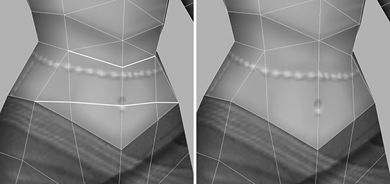
1. Select the edges highlighted in Figure 10.30a, just at the base of her spine, and collapse them as shown in Figure 10.30b.

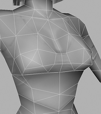
2. There are quite a few areas to reduce on the torso; let’s do them all at once. Follow Figure 10.30, selecting and collapsing the edges that are marked in white on both front (Figure 10.30c) and back (Figure 10.30e). After you make these changes, the torso should now resemble Figures 10.30d and 10.30f.
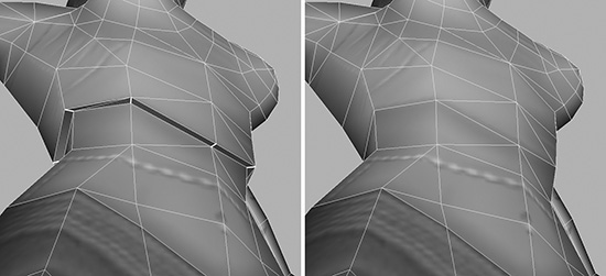
3. Next, collapse the edges that form the overhang of her top (Figure 10.31).
4. There are still quite a few polygons in her stomach that we don’t need, so delete those (Figure 10.32).
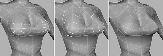
5. Work your way along as shown in Figure 10.33 to collapse the edges on the breasts.
6. Under the breasts, collapse the edges highlighted in Figure 10.34, left.

7. On the chest and at the cleavage, remove all of the geometry highlighted in Figure 10.35, left.
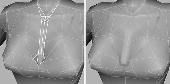
8. Finish off the chest area by working on its general shape (Figure 10.36). Remember to use LOD 2 as a guide.
Note
Don’t forget the UVs–correct any incorrect areas as you progress.
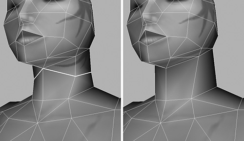
9. To complete your work in the torso area, quickly remove the division in her neck (Figure 10.37, left), making it a single flat area (Figure 10.37, right).
Only the accessories are left to finish the reductions for LOD 3.
Belt and Shoe Reduction
Although we could just delete the belt, it is still slightly visible at this distance, so we’ll take the time to reduce the number of polygons used to construct it. Then we’ll work on the shoes.
1. Remove the inside polygons on the belt, as well as the upper and lower edges (Figure 10.38a).
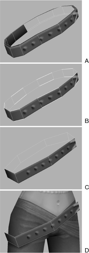
2. Collapse every other set of edges, removing every second polygon (Figure 10.38b and c).
3. Adjust the shape of the belt so it does not cut through the character model (Figure 10.38d).
4. To complete this LOD, reduce the shoes until they resemble Figure 10.39, right.
LOD 3 is finished. Look at the polygon count to make sure you are below the limit of 1000. Good—the final count is 794, well under the limit. Rename both the geometry group and the display layer to reflect this number. Figure 10.40 shows the third level of detail; as you can see, Kila is now starting to look quite different from her original form.
We are beginning to see some dramatic alterations to Kila’s geometry. When we are finished with the next two LODs, she will be almost unrecognizable up close.
LOD 4: 500 Polygons
Figure 10.41 shows the next LOD’s distance from the camera. As you can see, we are getting quite far from our character and can no longer see any details. All we can see is her basic shape.
1. Just as you did before, duplicate the previous LOD’s group and rename it to Kila500, placing it into a new display layer called Kila_500.
2. Start by deleting her belt, which is no longer visible at this distance.
3. On the hands, remove the thumb before reducing both hands right down to their basic shapes (Figure 10.42).
4. The arms currently have five divisions around the axis, so we can reduce them down to four (Figure 10.43). Select the edges at the very front of the arm, and collapse them.
5. Now you can remove the polygons that add shape to the arms, shown in Figure 10.43, middle. Again, these won’t be visible when the camera is at this distance, so it’s safe to remove them.
6. Moving on to the hair now, this can be reduced to a basic box shape like the one in Figure 10.44, right. You can even remove all of the internal geometry, if any still exists.
7. Reduce the face as demonstrated in Figure 10.45, removing the details for her eyes, nose, and lips and leaving her face more or less flat.
8. The legs can be reduced in the same way as you did the arms. Select the edges at the front and collapse them, reducing the divisions around the legs from five to four (Figure 10.46).
9. When the legs are reduced, you will notice areas around the crotch and waist that can be optimized. At this level, polygons to aid deformation are not needed, so select and collapse the edges highlighted in Figure 10.47 top-left and top-right.
10. Now you’ve come to the torso. You only need the basic shape to represent the character, so there are quite a few areas you can reduce here. Remove the edges shown in Figure 10.48 top-left and bottom-left, giving you the torso seen in the top-right and bottom-right of Figure 10.48. After removing the polygons, you will need to fine-tune the shape slightly.
11. Finally, work on the shoe, reducing it down to the basic shape seen in Figure 10.49, right.
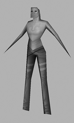
LOD 4 is now complete and you can see it in Figure 10.50.
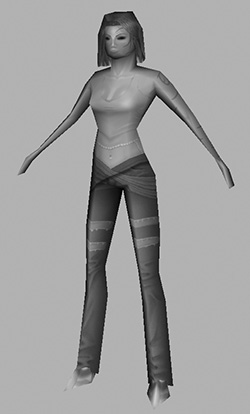
Checking the polygon count shows we are down to 309—another successful reduction. Rename the group and display layer to reflect the correct polygon count, and move on to create the final level of detail
LOD 5: 150 Polygons
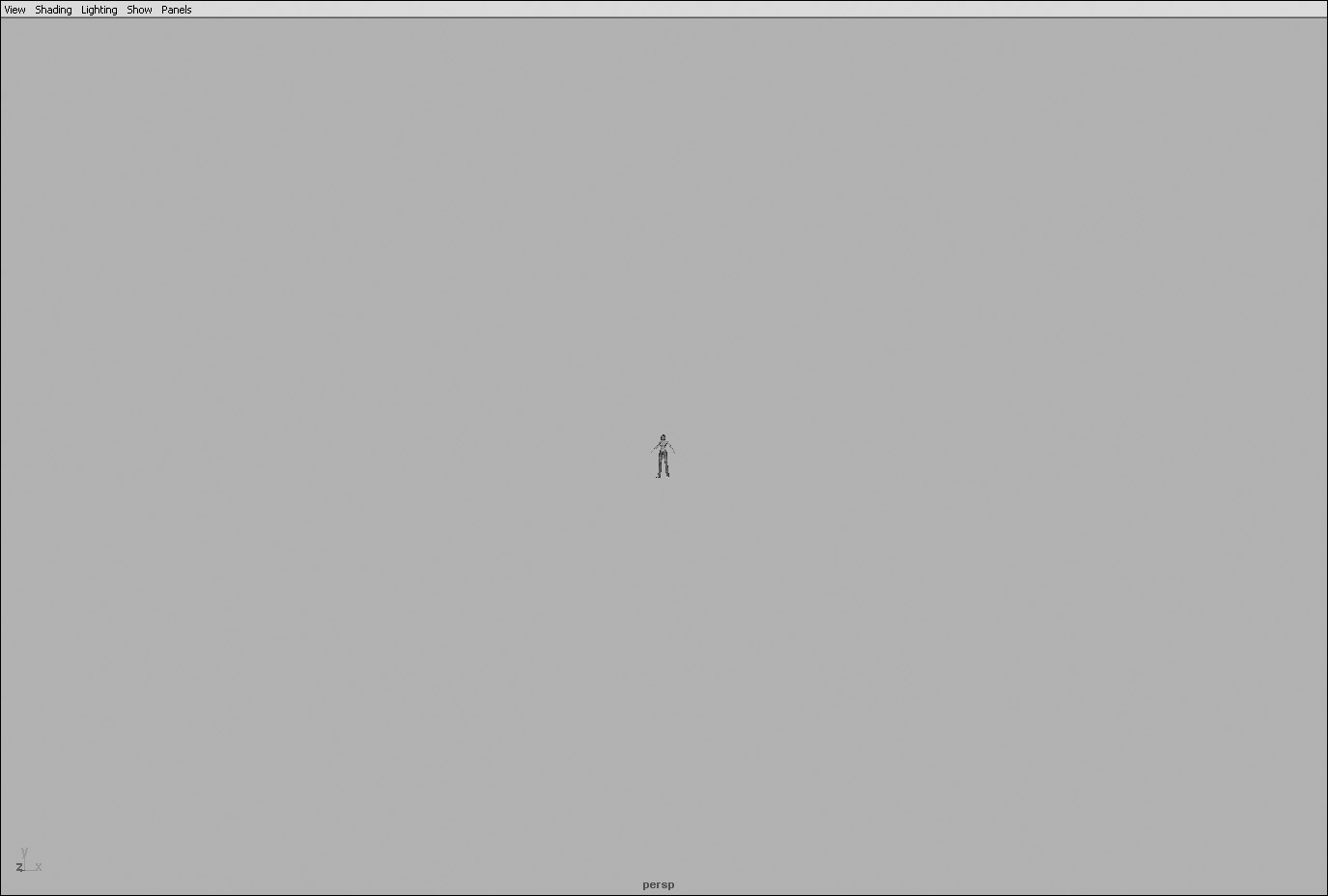
We are now at the final level of detail, the most basic version of our character. Figure 10.51 shows the distance at which this version will be activated; not much at all can be seen. We can just about make out arms, legs, and a torso, so these are the areas we will concentrate on.
1. Create a copy of the LOD 4, renaming it to Kila150.
2. Place this copy into a new display layer called Kila_150, and hide the display layer of the previous version.
3. Delete the hair and shoes.
4. You only need a vague representation of arms, so completely remove the hands, merging the end of each arm into a single vertex (Figure 10.52).
5. You won’t see the face at all at this distance, but you do need something to represent her head. Delete the faces under her chin, and then work on the head until it’s a basic flat cube like the one in Figure 10.53. Not only will this use fewer polygons, but it will work well from a distance.
6. Remove any extra polygons on the legs that add to their shape. All you need at this stage are very basic cube shapes (Figure 10.54).
7. Finally, there’s no need for details on her torso, either. You just want a basic shape, so remove the areas highlighted in Figure 10.55 top-left and bottom-left to make them like Figure 10.55 top-right and bottom-right.
Our final level of detail weighs in at 120 polygons. She’s not much to look at (Figure 10.56), but you have to remember she will never be seen this close in the game. Rename the final group and display layer to represent the polygon count (Kila_120) and save the file as Kila_LOD_Prep.mb.
Our LOD model for Kila is complete, but will it work? Once we have completed the reductions on Grae, we will test both characters’ LODs to see how they will look in a game when the characters move away from the camera.
Load in the file you created earlier, Grae_Pose.mb.
The main Grae model is 5174 polygons, so generate levels of detail at around the following polygon limits: 4000, 1500, 750, 350, and 150. He is a much larger character than Kila, so he will need an extra LOD.
Remember that each LOD will be roughly twice the distance away from the camera as the next-higher one, so keep zooming out to that level to check your progress.
Here are a few areas to consider:
![]() Grae’s teeth and claws hold a lot of polygons and will ultimately not be seen from a distance. Try removing the back faces from his teeth first.
Grae’s teeth and claws hold a lot of polygons and will ultimately not be seen from a distance. Try removing the back faces from his teeth first.
![]() If you are struggling to meet your LOD limits, consider removing the wings completely when he is far from the camera—but this is something you’d want to check out with your manager first.
If you are struggling to meet your LOD limits, consider removing the wings completely when he is far from the camera—but this is something you’d want to check out with your manager first.
![]() Remember to consider the hands for reduction as well as the limbs. Their need to deform correctly fades, the farther they get from the camera.
Remember to consider the hands for reduction as well as the limbs. Their need to deform correctly fades, the farther they get from the camera.
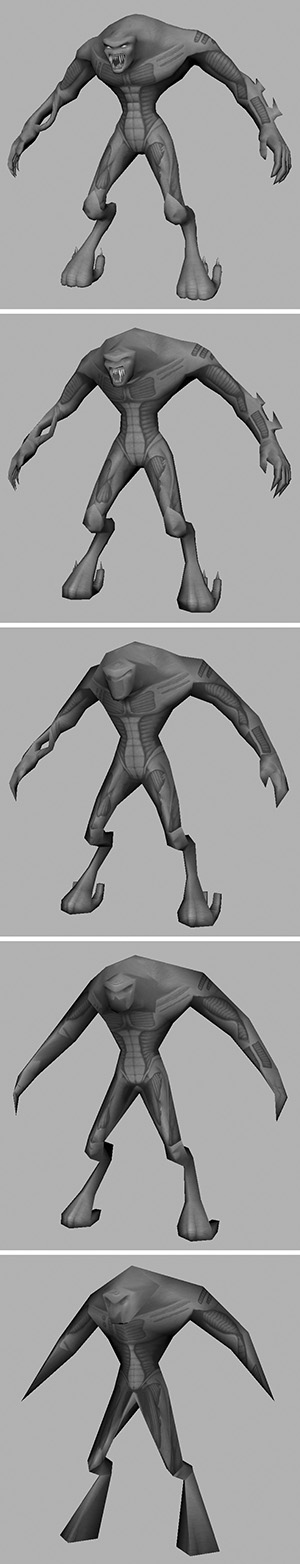
When finished, save your work as Grae_LOD_Prep.mb. You can see Grae’s LODs in Figure 10.57.
Testing LODs: The Level of Detail Group
Knowing how the levels of detail will look in the game can be guesswork at times. It usually involves your actually seeing the character in the game—but Maya has a way around this requirement. Maya allows you to view the models interactively using a Level of Detail Group. The programmers on your team can then use the data in this group to help them set up the in-game LODs.
Much like a normal group, what the LOD Group does is group all the different resolutions together. Then you can designate at what distance each model should be viewed.
Let’s apply this technique to our characters, Kila first.
1. Load in the file called Kila_LOD_Prep.mb. Make all the LODs visible in the Layer Editor.
2. In the Outliner, select the highest LOD group first (Kila4096). Then, holding Ctrl, select the lower ones in order.
3. Go to Edit > Level Of Detail > Group. Each version of your character will now be placed into a new group called lodGroup1. This group will now control each LOD’s visibility.
4. Try dollying the camera in and out of the screen; the character will change depending on its distance from the camera. The problem at the moment is that the distances are not set up correctly.
5. If it’s not currently selected, select the lodGroup1 group and look in the Channel Box (Figure 10.58).
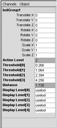
In the Channel Box, you’ll see that we have some new attributes in addition to the usual translate, rotate, scale, and visibility attributes.
![]() Active Level tells you which LOD is currently being viewed.
Active Level tells you which LOD is currently being viewed.
![]() Threshold[0]–[3] are the distances at which the LODs change.
Threshold[0]–[3] are the distances at which the LODs change.
![]() Distance is the character’s current distance from the camera.
Distance is the character’s current distance from the camera.
![]() Display Level[0]–[4] hold various display options for each individual LOD.
Display Level[0]–[4] hold various display options for each individual LOD.
6. We will use the Distance attribute to help us fill in the Threshold attributes correctly. Dolly out to the distance where the LOD will first change to level 2, using Figure 10.13 as reference. When you’re there, copy the value from the Distance attribute into the Threshold[0] attribute. It should be 5, or about that.
7. Do the same for the rest of the LODs, updating the associated Threshold attribute for each level. The values should be approximately 15 for Threshold[1], 43 for Threshold[2], and 123 for Threshold[3].
Now, as you move in and out from your character, the LODs will change according to the distances you have set.
8. Rename lodGroup1 to KilaLOD, and save the scene as Kila_LOD_Active.mb to show that the LODs are all set up accordingly.
Now you can follow these same steps on the Grae model; for him, set the LOD thresholds to 35, 90, 170, 330, and 700.
Summary
With this chapter complete, Kila and Grae have been designed, modeled, optimized, and textured, and now we have generated their levels of detail in order to save processing power. That is all the modeling we will be doing for now.
In Chapter 11, we will get some experience with Maya’s animation tools as we provide the skeletons that will enable our characters to move and interact with the gaming environment.