
Chapter 4. Introduction to Cortex-M0 Programming
Introduction to Embedded System Programming
All microcontrollers need program code to enable them to perform their intended tasks. If your only experience comes from developing programs for personal computers, you might find the software development for microcontrollers very different. Many embedded systems do not have any operating systems (sometimes these systems are referred as bare metal targets) and do not have the same user interface as a personal computer. If you are completely new to microcontroller programming, do not worry. Programming the Cortex-M0 is easy. As long as you have a basic understanding of the C language, you will soon be able develop simple applications on the Cortex-M0.
What Happens When a Microcontroller Starts?
Most modern microcontrollers have on-chip flash memory to hold the compiled program. The flash memory holds the program in binary machine code format, and therefore programs written in C must be compiled before programmed to the flash memory. Some of these microcontrollers might also have a separate boot ROM, which contains a small boot loader program that is executed when the microcontroller starts, before executing the user program in the flash memory. In most cases, only the program code in the flash memory can be changed and the boot loader is fixed.
After the flash memory (or other types of program memory) is programmed, the program is then accessible by the processor. After the processor is reset, it carries out the reset sequence, as outlined at the end of the previous chapter (Figure 4.1).
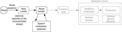
In the reset sequence, the processor obtains the initial MSP value and reset vector, and then it executes the reset handler. All of this required information is usually stored in a program file called startup code. The reset handler in the startup code might also perform system initialization (e.g., clock control circuitry and Phase Locked Loop [PLL]), although in most cases system initialization is carried out later when the C program “main()” starts. Example startup code can usually be found in the installation of the development suite or from software packages available from the microcontroller vendors. For example, if the Keil Microcontroller Development Kit (MDK) is used for development, the project creation wizard can optionally copy a default startup code file into your project that matches the microcontroller you selected.
For applications developed in C, the C startup code is executed before entering the main application code. The C startup code initializes variables and memory used by the application, and they are inserted to the program image by the C development suite (Figure 4.2).
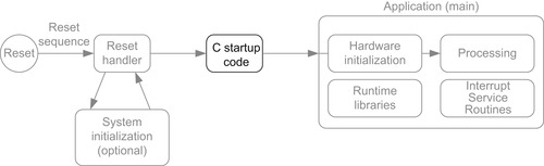
After the C startup code is executed, the application starts. The application program often contains the following elements:
• Initialization of hardware (e.g., clock, PLL, peripherals)
• The processing part of the application
• Interrupt service routines
In addition, the application might also use C library functions (Figure 4.3). In such cases, the C compiler/linker will include the required library functions into the compiled program image.
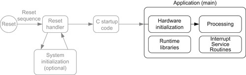
The hardware initialization might involve a number of peripherals, some system control registers, and interrupt control registers inside the Cortex-M0 processors. The initialization of the system clock control and the PLL might also take place if this were not carried out in the reset handler. After the peripherals are initialized, the program execution can then proceed to the application processing part.
Designing Embedded Programs
There are many ways to structure the flow of the application processing. Here we will cover a few fundamental concepts.
Polling
For simple applications, polling (sometimes also called super loop) is easy to set up and works fairly well for simple tasks (Figure 4.4).
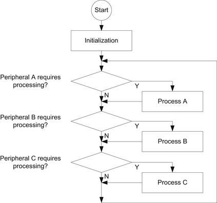
However, when the application gets complicated and demands higher processing performance, polling is not suitable. For example, if one of the processes takes a long time, other peripherals will not receive any service for some time. Another disadvantage of using the polling method is that the processor has to run the polling program all the time, even if it requires no processing.
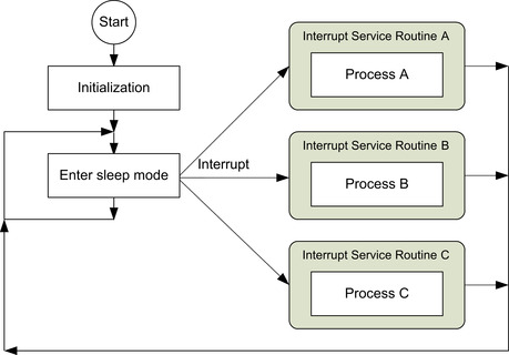
Interrupt Driven
In applications that require lower power, processing can be carried out in interrupt service routines so that the processor can enter sleep mode when no processing is required. Interrupts are usually generated by external sources or on chip peripherals to wake up the processor.
In interrupt-driven applications (Figure 4.5), the interrupts from different devices can be set at different priorities. In this way a high-priority interrupt request can obtain service even when a lower-priority interrupt service is running, which will be temporarily stopped. As a result, the latency for the higher-priority interrupt is reduced.
Combination of Polling and Interrupt Driven
In many cases, applications can use a combination of polling and interrupt methods (Figure 4.6). By using software variables, information can be transferred between interrupt service routines and the application processes.
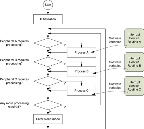
By dividing a peripheral processing task into an interrupt service routine and a process running in the main program, we can reduce the duration of interrupt services so that even lower-priority interrupt services gain a better chance of getting serviced. At the same time, the system can still enter sleep mode when no processing task is required. In Figure 4.6, the application is partitioned into processes A, B, and C, but in some cases, an application cannot be partitioned into individual parts easily and needs to be written as a large combined process.
Handling Concurrent Processes
In some cases, an application process could take a significant amount of time to complete and therefore it is undesirable to handle it in a big loop as shown in Figure 4.6. If process A takes too long to complete, processes B and C will not able to respond to peripheral requests fast enough, resulting in system failure. Common solutions are as follows:
1. Breaking down a long processing task to a sequence of states. Each time the process is accessed, only one state is executed.
2. Using a real-time operating system (RTOS) to manage multiple tasks.
For method 1, a process is divided into a number of parts, and software variables are used to track the state of the process (Figure 4.7). Each time the process is executed, the state information is updated so that next time the process is executed, the processing can resume correctly.
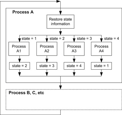
Because the execution path of the process is shortened, other processes in the main loop can be reached quicker inside the big loop. Although the total processing time required for the processing remains unchanged (or increases slightly because of the overhead of state saving and restoring), the system is more responsive. However, when the application tasks become more complex, partitioning the application task manually can become impractical.
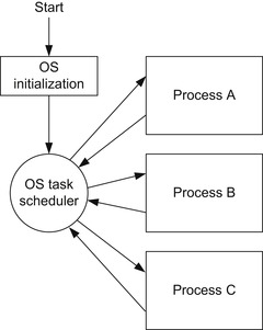
For more complex applications, a real-time operating system (RTOS) can be used (Figure 4.8). An RTOS allows multiple application processes to be executed by dividing processor execution time into time slots and allocating one to each task. To use an RTOS, a timer is needed to generate regular interrupt requests. When each time slot ends, the timer generates an interrupt that triggers the RTOS task scheduler, which determines if context switching should be carried out. If context switching should be carried out, the task schedule suspends the current executing task and then switches to the next task that is ready to be executed.
Using an RTOS improves the responsiveness of a system by ensuring that all tasks are reached within a certain amount of time. Examples of using an RTOS are covered in Chapter 18.
Inputs and Outputs
On many embedded systems, the available inputs and outputs can be limited to simple electronic interfaces like digital and analog inputs and outputs (I/Os), UARTs, I2C, SPI, and so on. Many microcontrollers also offer USB, Ethernet, CAN, graphics LCD, and SD card interfaces. These interfaces are handled by peripherals in the microcontrollers.
On Cortex-M0 microcontrollers, peripherals are controlled by memory-mapped registers (examples of accessing peripherals are presented later in this chapter). Some of these peripherals are more sophisticated than peripherals available on 8-bit and 16-bit microcontrollers, and there might be more registers to program during the peripheral setup.
Typically, the initialization process for peripherals may consist of the following steps:
1.
Programming the clock control circuitry to enable the clock signal to the peripheral and the corresponding I/O pins if necessary. In many low-power microcontrollers, the clock signals reaching different parts of the chip can be turned on or off individually to save power. By default, most of the clock signals are usually turned off and need to be enabled before the peripherals are programmed. In some cases you also need to enable the clock signals for the peripherals bus system.
2.
Programming of I/O configurations. Most microcontrollers multiplex their I/O pins for multiple uses. For a peripheral interface to work correctly, the I/O pin assignment might need to be programmed. In addition, some microcontrollers also offer configurable electrical characteristics for the I/O pins. This can result in additional steps in I/O configurations.
3.
Peripheral configuration. Most interface peripherals contain a number of programmable registers to control their operations, and therefore a programming sequence is usually needed to allow the peripheral to work correctly.
4.
Interrupt configuration. If a peripheral operation requires interrupt processing, additional steps are required for the interrupt controller (e.g., the NVIC in the Cortex-M0).
Most microcontroller vendors provide device driver libraries for peripheral programming to simplify software development. Unlike programming on personal computers, you might need to develop your own user interface functions to design a user-friendly standalone embedded system. However, the device driver libraries provided by the microcontroller vendors will make the development of your user interface easier.
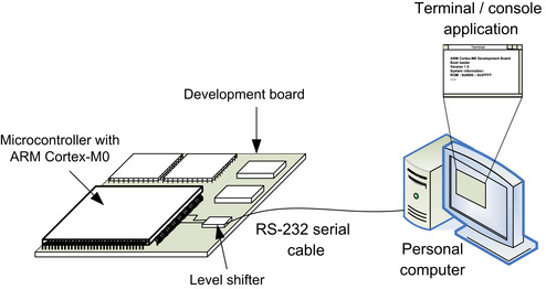
For the development of most deeply embedded systems, it is not necessary to have a rich user interface. However, basic interfaces like LEDs, DIP switches, and push buttons can deliver only a limited amount of information. For debugging software, a simple text input/output console is often sufficient. This can be handled by a simple RS-232 connection through a UART interface on the microcontroller to a UART interface on a personal computer (or via a USB adaptor) so that we can display the text messages and enter user inputs using a terminal application (Figure 4.9).
The technique to redirect text messages from a “printf” (in C language) to a UART (or another interface) is commonly referred to as “retargeting.” Retargeting can also handle user inputs and system functions. Examples of simple retargeting will be presented in later chapters of this book.
Typically, microcontrollers also provide a number of general-purpose input and output ports (GPIOs) that are suitable for simple control, user buttons or switches, LEDs, and the like. You can also develop an embedded system with a full feature graphics display using a microcontroller with built-in LCD controllers or using an external LCD module with a parallel or SPI interface. Although microcontroller vendors usually provide device driver libraries for the peripheral blocks, you might still need to develop your own user input and output functions.
Development Flow
Many development tool chains are available for ARM microcontrollers. The majority of them support C and assembly language. Embedded projects can be developed in either C or assembly language, or a mixture of both. In most cases, the program-generation flow can be summarized in a diagram, as shown in Figure 4.10.
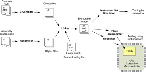
In most simple applications, the programs can be completely written in the C language. The C compiler compiles the C program code into object files and then generates the executable program image file using the linker. In the case of GNU C compilers, the compile and linking stages are often merged into one step.
Projects that require assembly programming use the assembler to generate object code from assembly source code. The object files can then be linked with other object files in the project to produce an executable image. Besides the program code, the object files and the executable image may also contain various debug information.
Depending on the development tools, it is possible to specify the memory layout for the linker using command line options. However, in projects using GNU C compilers, a linker script is normally required to specify the memory layout. A linker script is also required for other development tools when the memory layout gets complicated. In ARM development tools, the linker scripts are often called scatter-loading files. If you are using the Keil Microcontroller Development Kit (MDK), the scatter-loading file is generated automatically from the memory layout window. You can use your own scatter file if you prefer.
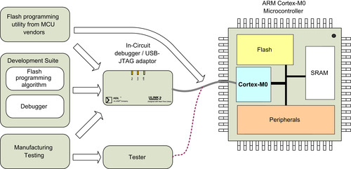
After the executable image is generated, we can test it by downloading it to the flash memory or internal RAM of the microcontroller. The whole process can be quite easy; most development suites come with a user-friendly integrated development environment (IDE). When working together with an in-circuit debugger (sometimes referred to as an in-circuit emulator [ICE], debug probe, or USB-JTAG adaptor), you can create a project, build your application, and download your embedded application to the microcontroller in a few steps (Figure 4.11).
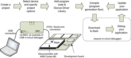
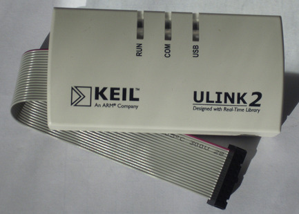
In many cases, an in-circuit debugger is needed to connect the debug host (personal computer) to the target board. The Keil U-LINK2 is one of the products available and can be used with Keil MDK and CodeSourcery g++ (Figure 4.12).
The flash programming function can be carried out by the debugger software in the development suite (Figure 4.13) or in some cases by a flash programming utility downloadable from microcontroller vendor web site. The program can then be tested by running it on the microcontroller, and by connecting the debugger to the microcontroller, the program execution can be controlled and the operations can be observed. All these actions can be carried out via the debug interface of the Cortex-M0 processor.
For simple program codes, we can also test the program using a simulator. This allows us to have full visibility to the program execution sequence and allows testing without actual hardware. Some development suites provide simulators that can also imitate peripheral behavior. For example, Keil MDK provides device simulation for many ARM Cortex microcontrollers.
Apart from the fact that different C compilers perform differently, different development suites also provide different C language extension features, as well as different syntax and directives in assembly programming. Chapter 5, Chapter 6 and Chapter 16 provide assembly syntax information for ARM development tools (including ARM RealView Development Suite [RVDS] and Keil MDK) and GNU C compilers. In addition, different development suites also provide different features in debug, utilities, and support different debug hardware product range.
C Programming and Assembly Programming
The Cortex-M0 processor can be programmed using C language, assembly language, or a mix of both. For beginners, C language is usually the best choice as it is easier to learn and most modern C compilers are very good at generating efficient code for the Cortex microcontrollers. Table 4.1 compares the use of C language and assembly language.
Most C compilers provide workarounds to allow assembly code to be used within C program code. For example, ARM C compilers provide an
Embedded Assembler so that assembly functions can be included in C program code easily. Similarly, most other C compilers provide an
Inline Assembler for inlining assembly code within a C program file. However, the assembly syntax for using an Embedded Assembler and Inline Assembler are tool specific (not portable). Note that the ARM C compiler has an Inline Assembler feature as well, but this is only available for 32-bit ARM instructions (e.g., for ARM7TDMI). Because the Cortex-M0 processor supports the Thumb instruction set only, the Embedded Assembler is used.
Some C compilers (including ARM C compilers in RealView Development Suite and Keil MDK) also provide intrinsic functions to allow special instructions to be used that cannot be generated using normal C code. Intrinsic functions are normally tool dependent. However, a tool-independent version of similar functions for Cortex-M0 is also available via the Cortex Microcontroller Software Interface Standard (CMSIS). This will be covered later in the chapter.
As Figure 4.10 shows, you can mix C and assembly code together in a project. This allows most parts of the program to be written in C, and some parts that cannot be handled in C can be written in assembly code. To do this, the interface between functions must be handled in a consistent manner to allow input parameters and returned results to be transferred correctly. In ARM software development, the interface between functions is specified by a specification document called the ARM Architecture Procedure Call Standard (AAPCS, reference 4). The AAPCS is part of the Embedded Application Binary Interface (EABI). When using the Embedded Assembler, you should follow the guidelines set by the AAPCS. The AAPCS document and the EABI document can be downloaded from the ARM web site.
More details in this area are covered in Chapter 16.
What Is in a Program Image?
At the end of Chapter 3 we covered the reset sequence of the Cortex-M0 and briefly introduced the vector table. Now we will look at the program image in more detail.
A program image for the Cortex-M0 microcontroller often contains the following components:
• Vector table
• C startup routine
• Program code (application code and data)
• C library code (program codes for C library functions, inserted at link time)
Vector Table
The vector table can be programmed in either C language or assembly language. The exact details of the vector table code are tool chain dependent because vector table entries require symbols created by the compiler and linker. For example, the initial stack pointer value is linked to stack region address symbols generated by the linker, and the reset vector is linked to C startup code address symbols, which are compiler dependent. For example, in the RealView Development Suite (RVDS), you can define the vector table with the following C code:
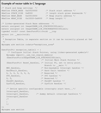 |
Some development tools, including Keil MDK, create the vector table as part of the assembly startup code. In this case, the Define Constant Data (DCD) directive is used to create the vector table.
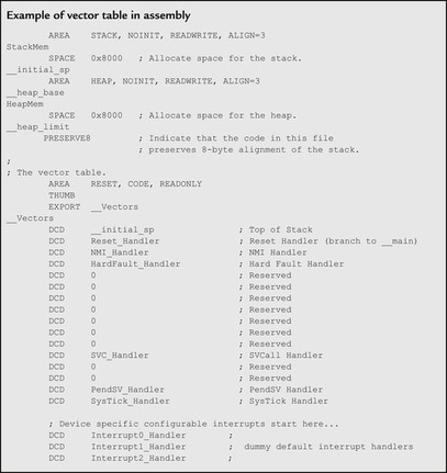 |
You might notice that in both examples, the vector tables are given section names (
exceptions_area in the C example and
RESET in the assembly example). The vector table needs to be placed at the beginning of the system memory map (address 0x00000000). This can be done by a linker script or command line option, which requires a section name so that the contents of the vector table can be identified and mapped correctly by the linker.
In normal applications, the reset vector can point to the beginning of the C startup code. However, you can also define a reset handler to carry out additional initialization before branching to the C startup code.
C Startup Code
The C startup code is used to set up data memory such as global data variables. It also zero initializes part of the data memory for variables that are uninitialized at load time. For applications that use C functions like malloc(), the C startup code also needs to initialize the data variables controlling the heap memory. After this initialization, the C startup code branches to the beginning of the main() program.
The C startup code is inserted by the compiler/linker automatically and is tool chain specific; it might not be present if you are writing a program purely in assembly. For ARM compilers, the C startup code is labeled as “__main,” whereas the startup code generated by GNU C compilers is normally labeled as “_start.”
Program Code
The instructions generated from your application program code carry out the tasks you specify. Apart from the instruction sequence, there are also various types of data:
• Initial values of variables. Local variables in functions or subroutines need to be initialized, and these initial values are set up during program execution.
• Constants in program code. Constant data are used in application codes in many ways: data values, addresses of peripheral registers, constant strings, and so on. These data are sometimes grouped together within the program images as a number of data blocks called literal pools.
• Some applications can also contain additional constant data like lookup tables and graphics image data (e.g., bit map) that are merged into the program images.
C Library Code
C library code is injected in to the program image by the linker when certain C/C++ functions are used. In addition, C library code can also be included because of data processing tasks such as floating point operations and divide. The Cortex-M0 does not have a divide instruction, and this function typically needs to be carried out by a C library divide function.
Some development tools offer various versions of C libraries for different purposes. For example, in Keil MDK or ARM RVDS there is an option to use a special version of C library called Microlib. The Microlib is targeted for microcontrollers and is very small, but it does not offer all features of the standard C library. In embedded applications that do not require high data processing capability and have tight program memory requirement, the Microlib offers a good way to reduce code size.
Depending on the application, C library code might not be present in simple C applications (no C library function calls) or pure assembly language projects.
Apart from the vector table, which must be placed at the beginning of the memory map, there are no other constraints on the placement of the rest of the elements inside a program image. In some cases, if the layout of the items in the program memory is important, the layout of the program image can be controlled by a linker script.
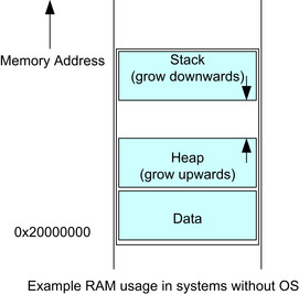
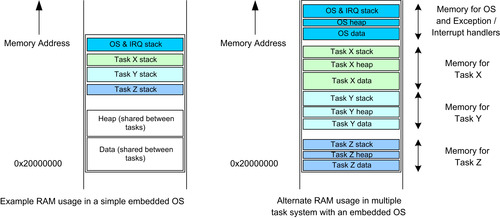
Data in RAM
Like program ROM, the RAM of microcontrollers is used in different ways. Typically, the RAM usage is divided into data, stack, and heap regions (Figure 4.14).
For microcontroller systems with an embedded OS (e.g., μClinux) or RTOS (e.g., Keil RTX), the stacks for each task are separate. Some OSs allow a user-defined stack for tasks that require larger stack memory. Some OSs divide the RAM into a number of segments, and each segment is assigned to a task, each containing individual data, stack, and heap regions (Figure 4.15).
So what is stored inside these data, stack, and heap regions?
•
Stack. The role of stack memory includes temporary data storage (normal stack PUSH and POP operations), memory space for local variables, parameter passing in function calls, register saving during an exception sequence, and so on. The Thumb instruction set is very efficient in handling data accesses that use a stack pointer (SP) related addressing mode and allows data in the stack memory to be accessed with very low instruction overhead.
•
Heap. The heap memory is used by C functions that dynamically reserve memory space, like “alloc(),” “malloc(),” and other function calls that use these functions. To allow these functions to allocate memory correctly, the C startup code needs to initialize the heap memory and its control variables.
Usually, the stack is placed at the top of the memory space and the heap memory is placed underneath. This gives the best flexibility for the RAM usage. In an OS environment, there can be multiple regions of data, stack, and heap in the RAM.
C Programming: Data Types
The C language supports a number of “standard” data types. However, the implementation of data type can be processor architecture dependent and C compiler dependent. In ARM processors including the Cortex-M0, the data type implementations shown in Table 4.2 are supported by all C compilers.
When porting applications from other processor architectures to ARM processors, if the data types have different sizes, it might be necessary to modify the C program code in order to ensure the program operates correctly. More details on porting software from 8-bit and 16-bit architecture are covered in Chapter 21.
In Cortex-M0 programming, the data variables stored in memory need to be stored at an address location that is a multiple of its size. More details on this area are covered in Chapter 7 (the data alignment section).
In ARM programming, we also refer to data size as word, half word, and byte (Table 4.3).
| Terms | Size |
|---|---|
| Byte | 8-bit |
| Half word | 16-bit |
| Word | 32-bit |
| Double word | 64-bit |
These terms are commonly found in ARM documentation, such as in the instruction set details.
Accessing Peripherals in C
Apart from data variables, a C program for microcontroller applications normally needs to access peripherals. In ARM Cortex-M0 microcontrollers, peripheral registers are memory mapped and can be accessed by memory pointers. In most cases, you can use the device drivers provided by the microcontroller vendors to simplify the software development task and make it easier to port software between different microcontrollers. If it is necessary to access the peripheral registers directly, the following methods can be used.
In simple cases of accessing a few registers, you can define a peripheral register as a pointer as follows:
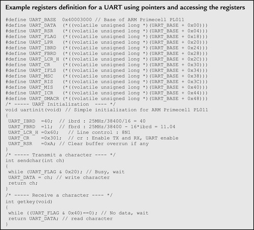 |
This solution is fine for simple applications. However, when multiple units of the same peripherals are available in the system, defining registers will be required for each of these peripherals, which can make code maintenance difficult. In addition, defining each register as a separated pointer might result in larger program size, as each register access requires a 32-bit address constant to be stored in the program flash memory.
To simplify the code, we can define the peripheral register set as a data structure and define the peripheral as a memory pointer to this data structure.
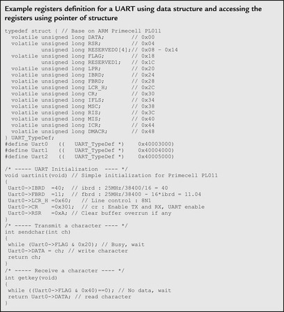 |
In this example, the Integer Baud Rate Divider (IBRD) register for UART #0 is accessed by the symbol
Uart0->IBRD, and the same register for UART #1 is accessed by
Uart1->IBRD.
With this arrangement, the same register data structure for the peripheral can be shared between multiple instantiations, making code maintenance easier. In addition, the compiled code could be smaller because of the reduced requirement of immediate data storage.
With further modification, a function developed for the peripherals can be shared between multiple units by passing the base pointer to the function:
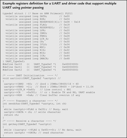
In most cases, peripheral registers are defined as 32-bit words. This is because most peripherals are connected to a peripheral bus (using APB protocol; see Chapter 7) that handles all transfers as 32 bit. Some peripherals might be connected to the processor bus (with AHB protocol that supports various transfer sizes; see Chapter 7). In such cases, the registers might be accessed in other transfer sizes. Please refer to the user manual of the microcontroller to determine the supported transfer size for each peripheral.
Note that when defining memory pointers for peripheral accesses, the “volatile” keyword should be used.
Cortex Microcontroller Software Interface Standard (CMSIS)
Introduction of CMSIS
As the complexity of embedded systems increase, the compatibility and reusability of software code becomes more important. Having reusable software often reduces development time for subsequent projects and hence speeds up time to market, and software compatibility helps the use of third-party software components. For example, an embedded system project might involve the following software components:
• Software from in-house software developers
• Software reused from other projects
• Device driver libraries from microcontroller vendors
• Embedded OS
• Other third-party software products like a communication protocol stack and codec (compressor/decompressor)
The use of the third-party software components is becoming more and more common. With all these software components being used in one project, compatibility is becoming critical for many large-scale software projects. To allow a high level of compatibility between these software products and improve software portability, ARM worked with various microcontroller vendors and software solution providers to develop the CMSIS, a common software framework covering most Cortex-M processors and Cortex-M microcontroller products (Figure 4.16).
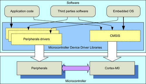
The CMSIS is implemented as part of device driver library from microcontroller vendors. It provides a standardized software interface to the processor features like NVIC control and system control functions. Many of these processors feature access functions are available in CMSIS for the Cortex-M0, Cortex-M3 and Cortex-M4, allowing easy software porting between these processors.
The CMSIS is standardized across multiple microcontroller vendors and is supported by multiple C compiler vendors. For example, it can be used with the Keil MDK, the ARM RealView Development Suite (RVDS), the IAR Embedded Workbench, the TASKING compiler, and various GNU-based C compiler suites including the CodeSourcery G++ tool chain.
What Is Standardized in CMSIS
The CMSIS standardized the following areas for embedded software:
•
Standardized access functions for accessing NVIC, System Control Block (SCB), and System Tick timer (SysTick) such as interrupt control and SysTick initialization. These functions will be covered in various chapters of this book and in the CMSIS functions quick reference in Appendix C.
•
Standardized register definitions for NVIC, SCB, and SysTick registers. For best software portability, we should use the standardized access functions. However, in some cases we need to directly access the registers in NVIC, SCB, or the SysTick. In such cases, the standardized register definitions help the software to be more portable.
•
Standardized functions for accessing special instructions in Cortex-M microcontrollers. Some instructions on the Cortex-M microcontroller cannot be generated by normal C code. If they are needed, they can be generated by these functions provided in CMSIS. Otherwise, users will have to use intrinsic functions provided by the C compiler or embedded/inline assembly language, which are tool chain specific and less portable.
•
Standardized names for system exceptions handlers. An embedded OS often requires system exceptions. By having standardized system exception handler names, supporting different device driver libraries in an embedded OS is much easier.
•
Standardized name for the system initialization function. The common system initialization function “void SystemInit(void)” makes it easier for software developers to set up their system with minimum effort.
•
Standardize variable for clock speed information. A standardized software variable called “SystemFreq” (CMSIS v1.00 to v1.20) or “SystemCoreClock” (CMSIS v1.30). This is used to determine the processor clock frequency.
• A common platform for device driver libraries—each device driver library has the same look and feel, making it easier for beginners to learn and making it easier for software porting.
• In future release of CMSIS, it could also provide a set of common communication access functions so that middleware that has been developed can be reused on different devices without porting.
The CMSIS is developed to ensure compatibility for the basic operations. Microcontroller vendors can add functions to enhance their software solution so that CMSIS does not restrict the functionality and the capability of the embedded products.
Organization of the CMSIS
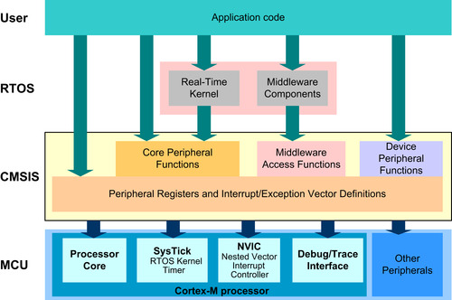
The CMSIS is divided into multiple layers:
Core Peripheral Access Layer
• Name definitions, address definitions, and helper functions to access core registers and core peripherals like the NVIC, SCB, and SysTick
Middleware Access Layer (work in progress)
• Common method to access peripherals for typical embedded systems
• Targeted at communication interfaces including UART, Ethernet, and SPI
• Allows embedded software to be used on any Cortex microcontrollers that support the required communication interface
Device Peripheral Access Layer (MCU specific)
• Register name definitions, address definitions, and device driver code to access peripherals
Access Functions for Peripherals (MCU specific)
• Optional helper functions for peripherals
The role of these layers is summarized in Figure 4.17.
Using CMSIS
The CMSIS is an integrated part of the device driver package provided by the microcontroller vendors. If you are using the device driver libraries for software development, you are already using the CMSIS. If you are not using device driver libraries from microcontroller vendors, you can still use CMSIS by downloading the CMSIS package from OnARM web site (www.onarm.com), unpacking the files, and adding the required files for your project.
For C program code, normally you only need to include one header file provided in the device driver library from your microcontroller vendor. This header file then pulls in the all the required header files for CMSIS features as well as peripheral drivers.
You also need to include the CMSIS-compliant startup code, which can be either in C or assembly code. CMSIS provides various versions of startup code customized for different tool chains.
Figure 4.18 shows a simple project setup using the CMSIS package. The name of some the files depends on the actual microcontroller device name (indicated as device in Figure 4.18). When you use the header file provided in the device driver library, it automatically includes the other required header files for you (Table 4.4).
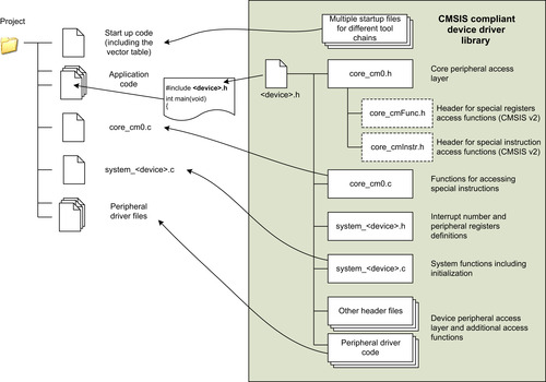
| Files | Descriptions |
|---|---|
| <device>.h | A file provided by the microcontroller vendor that includes other header files and provides definitions for a number of constants required by CMSIS, definitions of device specific exception types, peripheral register definitions, and peripheral address definitions. The actual filtername depends on the device. |
| core_cm0.h | The file core_cm0.h contains the definitions of the registers for processor peripherals like NVIC, System Tick Timer, and System Control Block (SCB). It also provides the core access functions like interrupt control and system control. This file and the file core_cm0.c provide the core peripheral access layer of the CMSIS. In CMSIS version 2, this file is spitted into multiple files (see Figure 4.18). |
| core_cm0.c | The file core_cm0.c provides intrinsic functions of the CMSIS. The CMSIS intrinsic functions are compiler independent. |
| Startup code | Multiple versions of the startup code can be found in CMSIS because it is tools specific. The startup code contains a vector table and dummy definitions for a number of system exceptions handler, and from version 1.30 of the CMSIS, the reset handler also executes the system initialization function “void SystemInit(void)” before it branches to the C startup code. |
| system_<device>.h | This is a header file for functions implemented in system_<device>.c |
| system_<device>.c | This file contains the implementation of the system initialization function “void SystemInit(void),” the definition of the variable “SystemCoreClock” (processor clock speed) and a function called “void SystemCoreClockUpdate(void)” that is used after clock frequency changes to update “SystemCoreClock.” The “SystemCoreClock” variable and the “SystemCoreClockUpdate” are available from CMSIS version 1.3. |
| Other files | There are additional files for peripheral control code and other helper functions. These files provide the device peripheral access layer of the CMSIS. |
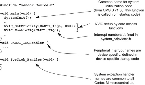
Figure 4.19 shows a simple example of using CMSIS.
Typically, information and examples of using CMSIS can be found in the device driver libraries package from your microcontroller vendor. There are also some simple examples of using the CMSIS in the CMSIS package on the OnARM web site (www.onarm.com).
Benefits of CMSIS
For most users, CMSIS offer a number of key advantages.
Porting of applications from one Cortex-M microcontroller to another Cortex-M microcontroller is much easier. For example, most of the interrupt control functions are available for Cortex-M0, Cortex-M3, and Cortex-M4 (only a few functions for Cortex-M3/M4 are not available for Cortex-M0 because of the extra functionality of the Cortex-M3/M4 processors). This makes it straightforward to reuse the same application code for a different project. You can migrate a Cortex-M3 project to Cortex-M0 for lower cost, or you can move a Cortex-M0 project to Cortex-M3 if higher performance is required.
Learning to use a new Cortex-M microcontroller is made easier. Once you have used one Cortex-M microcontroller, you can start using another quickly because all CMSIS device driver libraries have the same core functions and a similar look and feel.
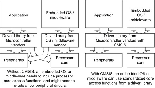
The CMSIS also lowers the risk of incompatibility when integrating third-party software components. Because middleware and an embedded RTOS will be based on the same core peripheral register definitions and core access functions in CMSIS files, this reduces the chance of conflicting code. This can happen when multiple software components carry their own core access functions and register definitions. Without CMSIS, you might possibly find that different third-party software programs contain unique driver functions. This could lead to register name clashes, confusion because of multiple functions with similar names, and a waste of code space as a result of duplicated functions (Figure 4.20).
CMSIS makes your software code future proof. Future Cortex-M microcontrollers will also have CMSIS support, so you can reuse your application code in future products.
The CMSIS core access functions have a small memory footprint. Multiple parties have tested CMSIS, and this helps reduce your software testing time. The CMSIS is Motor Industry Software Reliability Association (MISRA) compliant.
For companies developing an embedded OS or middleware products, the advantage of CMSIS is significant. Because CMSIS supports multiple compiler suites and is supported by multiple microcontroller vendors, the embedded OS or middleware developed with CMSIS can work on multiple complier products and can be used on multiple microcontroller families. Using CMSIS also means that these companies do not have to develop their own portable device drivers, which saves development time and verification efforts.
..................Content has been hidden....................
You can't read the all page of ebook, please click here login for view all page.