
Chapter 8. Exceptions and Interrupts
What Are Exceptions and Interrupts?
Exceptions are events that cause changes in program flow control outside a normal code sequence. When it happens, the program that is currently executing is suspended, and a piece of code associated with the event (the exception handler) is executed. The events could either be external or internal. When an event is from an external source, it is commonly known as an interrupt or interrupt request (IRQ). Exceptions and interrupts are supported in almost all modern processors. In microcontrollers, the interrupts can also be generated using on-chip peripherals or by software.
The software code that is executed when an exception occurs is called exception handler. If the exception handler is associated with an interrupt event, then it can also be called an interrupt handler, or interrupt service routine (ISR). The exception handlers are part of the program code in the compiled program image.
When the exception handler has finished processing the exception, it will return to the interrupted program and resume the original task. As a result, the exception handling sequence requires some way to store the status of the interrupted program and allow this information to be restored after the exception handler has completed its task. This can be done by a hardware mechanism or by a combination of hardware and software operations. In the next couple of chapters, we will see how the Cortex-M0 processor handles this process.
It is common to divide exceptions into multiple levels of priority, and while running an exception handler of a low priority exception, a higher priority exception can be triggered and serviced. This is commonly known as a nested exception. The priority level of an exception could be programmable or fixed. Apart from priority settings, some exceptions (including most interrupts) can also be disabled or enabled by software.
Exception Types on the Cortex-M0 Processor
The Cortex-M0 processor contains a built-in interrupt controller, which supports up to 32 interrupt request (IRQ) inputs, and a nonmaskable interrupt (NMI) input. Depending on the design of the microcontroller product, the IRQ and the NMI can be generated either from on-chip peripherals or external sources. In addition, the Cortex-M0 processor also supports a number of internal exceptions.
Each exception source in the Cortex-M0 processor has a unique exception number. The exception number for NMI is 2, and the exception numbers for the on-chip peripherals and external interrupt sources are from 16 to 47. The other exception numbers, from 1 to 15, are for system exceptions generated inside the processor, although some of the exception numbers in this range are not used.
Each exception type also has an associated priority. The priority levels of some exceptions are fixed and some are programmable. Table 8.1 shows the exception types, exception numbers, and priority levels.
Nonmaskable Interrupt (NMI)
The NMI is similar to IRQ, but it cannot be disabled and has the highest priority apart from the reset. It is very useful for safety critical systems like industrial control or automotive. Depending on the design of the microcontroller, the NMI could be used for power failure handling, or it can be connected to a watchdog unit to restart a system if the system stopped responding. Because the NMI cannot be disabled by control registers, the responsiveness is guaranteed.
Hard Fault
SVCall (SuperVisor Call)
SVC exception takes place when the SVC instruction is executed. SVC is usually used in systems with an operating system (OS), allowing applications to have access to system services.
PendSV (Pendable Service Call)
PendSV is another exception for applications with OS. Unlike the SVC exception, which must start immediately after the SVC instruction has been executed, PendSV can be delayed. The OS commonly uses PendSV to schedule system operations to be carried out only when high-priority tasks are completed.
SysTick
The System Tick Timer inside the NVIC is another feature for OS application. Almost all operating systems need a timer to generate regular interrupt for system maintenance work like context switching. By integrating a simple timer in the Cortex-M0 processor, porting an OS from one device to another is much easier. The SysTick timer and its exception are optional in the Cortex-M0 microcontroller implementation.
Interrupts
The Cortex-M0 microcontroller could support from 1 to 32 interrupts. The interrupt signals could be connected from on-chip peripherals or from an external source via the I/O port. In some cases (depending on the microcontroller design), the external interrupt number might not match the interrupt number on the Cortex-M0 processor.
External interrupts need to be enabled before being used. If an interrupt is not enabled, or if the processor is already running another exception handler with same or higher priority, the interrupt request will be stored in a pending status register. The pended interrupt request can be triggered when the priority level allows—for example, when a higher-priority interrupt handler has been completed and returned. The NVIC can accept interrupt request signals in the form of a high logic level, as well as an interrupt pulse (with a minimum of one clock cycle). Note that in the external interface of a microcontroller, the external interrupt signals can be active high or active low, or they can have programmable configurations.
Exception Priority Definition
In the Cortex-M0 processor, each exception has a priority level. The priority level affects whether the exception will be carried out or if it will wait until later (stay in a pending state). The Cortex-M0 processor supports three fixed highest priority levels and four programmable levels. For exceptions with programmable priority levels, the priority level configuration registers are 8 bits wide, but only the two MSBs are implemented (Figure 8.1).
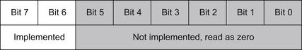
Because bit 5 to bit 0 are not implemented, they are always read as zero, and write to these bits are ignored. With this setup, we have possible priority levels of 0x00 (high priority), 0x40, 0x80, and 0xC0 (low priority). This is similar to the Cortex-M3 processor, except that on the Cortex-M3 processor it has at least 3 bits implemented, and therefore the Cortex-M3 processor has at least eight programmable priority levels, whereas the Cortex-M0 processor has only four. When combine with the three fixed priority levels, the Cortex-M0 processor has total of seven priority levels (Figure 8.2).

The reason for removing the LSB of the priority level register instead of the MSB is to make it easier to port software from one Cortex-M0/M3 device to another. In this way, a program written for devices with wider priority width registers is likely to be able run on devices with narrower priority widths. If the MSB is removed instead of the LSB, you might get an inversion of priority level arrangement among several exceptions during porting of the application. This might result in an exception that is expected to have a lower exception priority preempting another exception that was expected to have a higher priority.
If an enabled exception event occurs (e.g., interrupt, SysTick timer, etc.) while no other exception handler is running, and the exception is not blocked because of PRIMASK (the interrupt masking register, see descriptions in Chapter 3), then the processor will accept it and the exception handler will be executed. The process of switching from a current running task to an exception handler is called preemption.
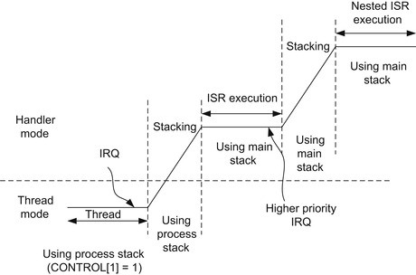
If the processor is already running another exception handler but the new exception has higher priority level than the current level, then preemption will also take place. The running exception handler will be suspended, and the new exception handler will be executed. This is commonly known as nested interrupt or nested exception. After the new exception handler is completed, the previous exception handler can resume execution and return to thread when it is completed.
However, if the processor is already running another exception handler that has the same or a higher priority level, the new exception will have to wait by entering a pending state. A pending exception can wait until the current exception level changes—for example, after the running exception handler has been completed and returned, and the current priority level has been lowered to be below the priority level of the pending exception. The pending status of exceptions can be accessed via memory-mapped registers in the NVIC. It is possible to clear the pending status of an exception by writing to an NVIC register in software. If the pending status of an exception is cleared, it will not be executed.
If two exceptions happen at the same time and they have the same programmed priority level, the exception with the lower exception type number will be processed first. For example, if both IRQ #0 and IRQ #1 are enabled, both have the same priority level, and both are asserted at the same time, IRQ #0 will be handled first. This rule only applies when the processor is accepting the exceptions, but not when one of these exceptions is already being processed.
The interrupt nesting support in the Cortex-M0 processor does not require any software intervention. This is different from traditional ARM7TDMI, as well as some 8-bit and 16-bit microcontroller architectures where interrupts are disabled automatically during interrupt services and require additional software processing to enable nest interrupt supports.
Vector Table
Traditionally, in processors like the ARM7TDMI, the starting address of the exception handler is fixed. Because the ARM7TDMI has only one IRQ input, multiple IRQs have to share the same IRQ handler starting point, and the handler has to access the status of the interrupt controller to determine which interrupt to be serviced. In the Cortex-M0 processor, the built-in interrupt controller NVIC supports vectored interrupts, which means the exception vectors for different interrupts are separated and the starting-of-interrupt-service routines are located automatically without software intervention.
When the Cortex-M0 processor starts to process an interrupt request, it needs to locate the starting address of the exception handler. This information is stored in the beginning of the memory space, called the vector table (Figure 8.3). The vector table contains the exception vectors for available exceptions in the system, as well as the starting value of the main stack pointer (MSP).
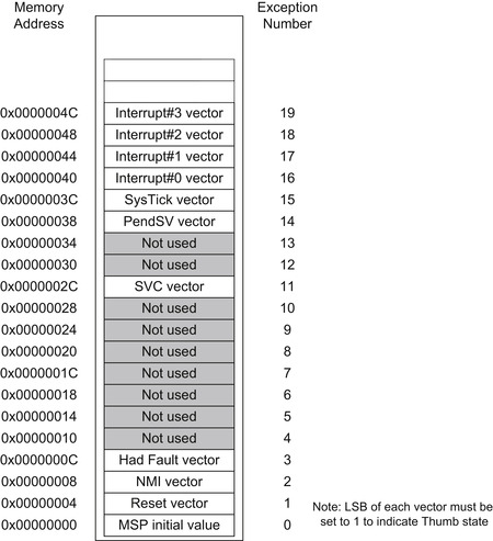
The order of exception vector being stored is the same order of the exception number. Because each vector is one word (four bytes), the address of the exception vector is the exception number times four. Each exception vector is the starting address of the exception handler, with the LSB set to 1 to indicate that the exception handler is in Thumb code.
Some of the spaces in the vector table are not used because the Cortex-M0 only has a few system exceptions. Some of the unused exceptions are used on other ARM processors like the Cortex-M3/M4 processor, as these processors have additional system exceptions.
Exception Sequence Overview
Acceptance of Exception Request
The processor accepts an exception if the following conditions are satisfied:
• For interrupt and SysTick interrupt requests, the interrupt has to be enabled
• The processor is not running an exception handler of the same or a higher priority
• The exception is not blocked by the PRIMASK interrupt masking register
Note that for SVC exception, if the SVC instruction is accidentally used in an exception handler that has the same or a higher priority than the SVC exception itself, it will cause the hard fault exception handler to execute.
Stacking and Unstacking
To allow an interrupted program to be resumed correctly, some parts of the current state of the processor must be saved before the program execution switches to the exception handler that services the occurred exception. Different processor architectures have different ways to do this. In the Cortex-M0 processor, the architecture uses a mixture of automatic hardware arrangement and, only if necessary, additional software steps for saving and restoring processor status.
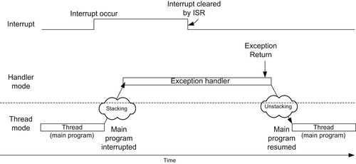
When an exception is accepted on the Cortex-M0 processor, some of the registers in the register banks (R0 to R3, R12, R14), the return address (PC), and the Program Status Register (xPSR) are pushed to the current active stack memory automatically. The Link Register (LR/R14) is then updated to a special value to be used during exception return (EXC_RETURN, to be introduced later in this chapter), and then the exception vector is automatically located and the exception handler starts to execute.
At the end of the exception handling process, the exception handler executes a return using the special value (EXC_RETURN, previously generated in LR) to trigger the exception return mechanism. The processor checks to determine if there is any other exception to be serviced. If not, the register values previously stored on the stack memory are restored and the interrupted program is resumed.
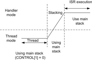
The actions of automatically saving and restoring of the register contents are called “stacking” and “unstacking” (Figure 8.4). These mechanisms allow exception handlers to be implemented as normal C functions, thereby reducing the software overhead of exception handling as well as the circuit size (no need to have extra banked registers), and hence lowering the power consumption of the design.
The registers not saved by the automatic stacking process will have to be saved and restored by software in the exception handler, if the exception handler had modified them. However, this does not affect the use of normal C functions as exception handlers, because it is a requirement for C compilers to save and restore the other registers (R4-R11) if they will be modified during the C function execution.
Exception Return Instruction
Unlike some other processors, there is no special return instruction for exception handlers. Instead, a normal return instruction is used and the value load into PC is used to trigger the exception return. This allows exception handlers to be implemented as a normal C function.
Two different instructions can be used for exception return:
BX <Reg>; Load a register value into PC (e.g., “BX LR”)
and
POP {<Reg1>,< Reg2>,….,PC}; POP instruction with PC being one of the registersbeing updated
When one of these instructions is executed with a special value called EXC_RETURN being loaded into the program counter (PC), the exception return mechanism will be triggered. If the value being loaded into the PC does not match the EXC_RETURN pattern, then it will be executed as a normal BX or POP instruction.
Tail Chaining
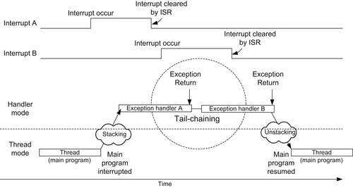
If an exception is in a pending state when another exception handler has been completed, instead of returning to the interrupted program and then entering the exception sequence again, a tail-chain scenario will occur. When tail chain occurs, the processor will not have to restore all register values from the stack and push them back to the stack again. The tail chaining of exceptions allows lower exception processing overhead and hence better energy efficiency (Figure 8.5).
Late Arrival
Late arrival is an optimization mechanism in the Cortex-M0 to speed up the processing of higher-priority exceptions. If a higher priority exception occurs during the stacking process of a lower-priority exception, the processor switches to handle the higher-priority exception first (Figure 8.6).
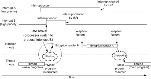
Because processing of either interrupt requires the same stacking operation, the stacking process continues as normal when the late-arriving, higher-priority interrupt occurs. At the end of the stacking process, the vector for the higher-priority exception is fetched instead of the lower-priority one.
EXC_RETURN
The EXC_RETURN is a special architecturally defined value for triggering and helping the exception return mechanism. This value is generated automatically when an exception is accepted and is stored into the Link Register (LR, or R14) after stacking. The EXC_RETURN is a 32-bit value; the upper 28 bits are all set to 1, and bits 0 to 3 are used to provide information for the exception return mechanism (Table 8.2).
Bit 0 of EXC_RETURN on the Cortex-M0 processor is reserved and must be 1.
Bit 2 of EXC_RETURN indicates whether the unstacking should restore registers from the main stack (using MSP) or process stack (using PSP).
Bit 3 of EXC_RETURN indicates whether the processor is returning to Thread mode or Handler mode.
Table 8.3 shows the valid EXC_RETURN values for the Cortex-M0 processor.
Because the EXC_RETURN value is loaded into LR automatically at the exception entry, the exception handler treats it as a normal return address. If the return address does not need to be saved onto the stack, the exception handler can trigger the exception return and return to the interrupt program by executing “BX LR,” just like a normal function. Alternatively, if the exception handler needs to execute function calls, it will need to push the LR to the stack. At the end of the exception handler, the stacked EXC_RETURN value can be loaded into PC directly by a POP instruction, thus triggering the exception return sequence and the return to the interrupt program.
The following diagrams show situations in which different EXC_RETURN values are generated and used.
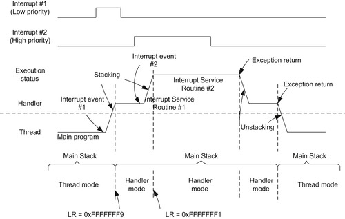
If the thread is using main stack (CONTROL register bit 1 is zero), the value of the LR will be set to 0xFFFFFFF9 when it enters an exception and 0xFFFFFFF1 when a nested exception is entered, as shown in Figure 8.7.
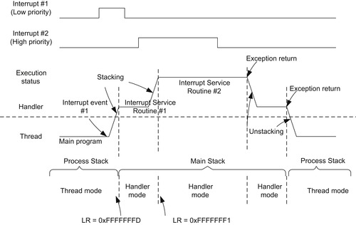
If the thread is using process stack (CONTROL register bit 1 is set to 1), the value of LR will be 0xFFFFFFFD when entering the first exception and 0xFFFFFFF1 when entering a nested exception, as shown in Figure 8.8.
As a result of EXC_RETURN format, a normal return instruction cannot return to an address in the range of 0xFFFFFFFX, because this will be treated as an exception return rather than a normal one. However, because the address range 0xFXXXXXXX is reserved and should not contain program code, it is not a problem.
Details of Exception Entry Sequence
When an exception takes place, a number of things happen:
• The stack pointer stacks and updates
• The processor fetches the vector and updates it to the PC
• The registers update (LR, IPSR, NVIC registers)
Stacking
When an exception takes place, eight registers are pushed to the stack automatically (Figure 8.9). These registers are R0 to R3, R12, R14 (the Link Register), the return address (address of the next instruction, or Program Counter), and the program status register (xPSR). The stack being used for stacking is the current active stack. If the processor was in Thread mode when the exception happened, the stacking could be done using either the process stack or the main stack, depending on the setting in the CONTROL register bit 1. If CONTROL[1] was 0, the main stack would be used for the stacking.
If the processor was in Thread mode and CONTROL[1] was set to 1 when the exception occurred, the stacking will be done using the process stack (Figure 8.10).
For nested exceptions, the stacking always uses the main stack because the processor is already in Handler mode, which can only use the main stack.
The reason for the registers R0–R3, R12, PC, LR, and xPSR to be saved to stack is that these are called “caller saved registers.” According to the AAPCS (ARM Architecture Procedure Call Standard, reference 4), a C function does not have to retain the values of these registers. To allow exception handlers to be implemented as normal C functions, these registers have to be saved and restored by hardware, so that when the interrupt program resumes, all these registers will be the same as they were before the exception occurred.
The grouping of the register contents that are pushed onto the stack during stacking is called a “stack frame” (Figure 8.11). In the Cortex-M0 processor, a stack frame is always double word aligned. This ensures that the stack implementation conforms to the AAPCS standard (reference 4). If the position of the last pushed data could be in an address that is not double word aligned, the stacking mechanism automatically adjusts the stacking position to the next double-word-aligned location and sets a flag (bit 9) in the stacked xPSR to indicate that the double word stack adjustment has been made.
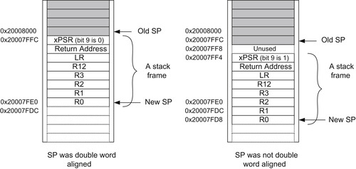
During unstacking, the processor checks the flag in the stacked xPSR and adjusts the stack pointer accordingly.
The stacking of registers is carried out in the order shown in Figure 8.12.
Vector Fetch and Update PC
After the stacking is done, the processor then fetches the exception vector from the vector table. The vector is then updated to the PC, and the instruction fetch of the exception handler execution starts from this address.
Registers Update
As the exception handler starts to execute, the value of LR is updated to the corresponding EXC_RETURN value. This value is to be used for exception return. In addition, the IPSR is also updated to the exception number of the currently serving exception.
In addition, a number of NVIC registers might also be updated. This includes the status registers for external interrupts if the exception taken is an interrupt, or the Interrupt Control and Status Register if it is a system exception.
Details of Exception Exit Sequence
When an exception return instruction is executed (loading of EXC_RETURN into PC by POP or BX instruction), the exception exit sequence begins. This includes the following steps:
• Unstacking of registers
• Fetching and executing from the restored return address
Unstacking of Registers
To restore the registers to the state they were in before the exception was taken, the register values that were stored on to the stack during stacking are read (POP) and restored back to the registers (Figure 8.13). Because the stack frame can be stored either on the main stack or on the processor stack, the processor first checks the value of the EXC_RETURN being used. If bit 2 of EXC_RETURN is 0, it starts the unstacking from the main stack. If this bit is 1, it starts the unstacking from the process stack.
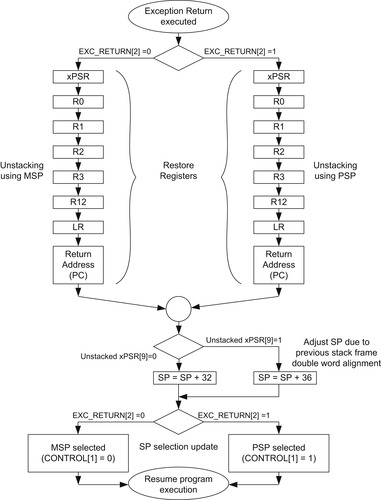
After the unstacking is done, the stack pointer needs to be adjusted. During stacking, a 4-byte space might have been included in the stack memory so as to ensure the stack frame is double word aligned. If this is the case, the bit 9 of the stack xPSR would be set to 1, and the value of SP could be adjusted accordingly to remove the 4-byte padding space.
In addition, the current SP selection may be switched back to the process stack if bit 2 of EXC_RETURN was set to 1 and bit 3 of the EXC_RETURN was set, indicating the exception exit is returning to Thread mode.
Fetch and Execute from Return Address
After the exception return process is completed, the processor can then fetch instructions from the restored return address in the program counter and resume execution of the interrupted program.
..................Content has been hidden....................
You can't read the all page of ebook, please click here login for view all page.