
Chapter 11. Low-Power Features
Low-Power Embedded System Overview
There are many types of low-power embedded systems, and different systems can have different low-power requirements. Typically, we can summarize these requirements into the categories outlined in Table 11.1.
In practice, most low-power embedded products will have to consider more than one of these low-power factors. For example, some of the embedded systems operate continuously and can be switched off completely when not in use. In this case, the low operating power would be the most important factor, whereas some systems might need to be in standby mode most of the time and only wake up to execute a program for a short period. In such a case, the low standby power would be the more critical requirement, especially if the battery life of the product is important.
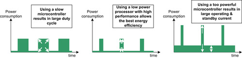
As embedded products are getting more and more complex, the computation capability of the processor is becoming more important. Nowadays a lot of embedded systems are interrupt driven (Figure 11.1); when there is no interrupt request, no data processing is required and the processor can enter sleep mode. When a peripheral requires servicing, it generates an interrupt request and wakes up the processor. The processor then handles the required processing and returns to sleep. The better processing capability the processor has, the more time it can stay in sleep mode and hence improve battery life.

If you are using a slow processor for an interrupt-driven system, the interrupt service routine could take a lot longer to run and increase the duty cycles of the system. But if you are using a very powerful processor, despite being able to reduce the duty cycles, you might end up with much more operating power and standby power, which will increase power consumption. Depending on the data processing requirements, different applications require different processors for the optimum balance between performance and power (Figure 11.2).
For this reason, there are different types of ARM processors for different application requirements. The ARM processors are designed with low-power embedded systems in mind. Different ARM processors are optimized for different groups of applications based on processing requirements. The Cortex-M0 processor is developed to target small embedded systems with ultra-low-power requirements and mixed-signal applications, where the processor design complexity is limited by various constraints in mixed-signal semiconductor technologies.
Low-Power Advantages of the Cortex-M0 Processor
So how does the Cortex-M0 processor satisfy the ultra-low-power requirements in an embedded application?
First, the design of the Cortex-M0 processor is very small. For a minimum implementation, the design is only 12K gates. It is smaller than many 16-bit processors and much smaller than other 32-bit processors on the market. This reduces both operating power and static power (caused by the leakage current of transistors).
Second, the design of the Cortex-M0 processor utilizes many low-power design techniques to reduce the operating power consumption. ARM has more than 20 years of low-power processor design experience. The design of the Cortex-M0 has been extensively reviewed to ensure that the low-power design measures are utilized for lowest power consumption. This allows the operating power of the processor to be reduced.
Even with a tiny footprint, the Cortex-M0 is still able to deliver a performance that is much higher than 8-bit and 16-bit systems that have the same clock rate. The Cortex-M0 processor also has the best in class energy efficiency in the 32-bit processor market because of its small size and low power consumption.
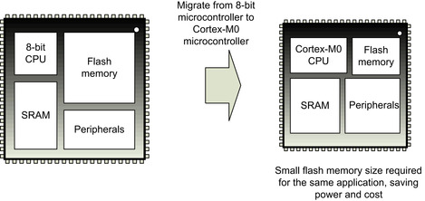
The high code density of the Cortex-M processors also lower power by reducing the size of the flash memory required. In modern microcontroller designs, the majority of the silicon area is occupied by flash memory, SRAM, and peripherals. With traditional 8-bit microcontroller architectures, the lack of flexible addressing modes, the heavy use of accumulator registers, and limited data paths often result in large program code (Figure 11.3). By switching to Cortex-M0 or other Cortex-M processors, the program size can be greatly reduced and hence you can use a microcontroller with a smaller flash to save power and cost.
 |
| Figure 11.3 |
In addition, when comparing the Cortex-M0 microcontroller products to 8-bit and 16-bit microcontroller products, the Cortex-M0 offers much higher performance. As a result, an embedded developer can reduce power consumption by taking the following steps:
• Reducing the operating frequency of the device
• Reducing the duty cycle of the device (putting the core into sleep for a longer time)
Either way, or by combining both approaches, the energy efficiency characteristics of the Cortex-M0 processor allow longer battery life in portable products compared with 8-bit and 16-bit microcontrollers. Besides extending battery life, the low-power capability of the Cortex-M0 processor also:
• Reduces noise to allow better accuracy in analog applications like sensors
• Reduces interference in wireless and radio frequency applications
• Allows a simpler and cost-effective power supply design for the system
Overview of the Low-Power Features
A number of low-power features are available in the Cortex-M0 processor. In addition, microcontroller vendors usually also implement a number of low-power modes in their Cortex-M0 microcontroller products. This chapter focuses mostly on the low-power features provided by the Cortex-M0 processor. Details for microcontroller specific low-power features are usually available in user manuals or application notes available from the microcontroller vendor web sites or in example software packages.
In general the Cortex-M0 processor includes the following low-power features:
•
Two architectural sleep modes: normal sleep and deep sleep. The sleep modes can be further extended with vendor-specific sleep control features. Within the processor, both sleep modes behave similarly. However, the rest of the microcontroller can typically reduce power by applying different methods to these two modes.
•
Two instructions for entering sleep modes. WFE (Wait for Event) and
WFI (Wait for Interrupt). Both can be used with normal sleep and deep sleep.
•
Sleep-on-exit (from exception) feature. This feature allows interrupt-driven applications to stay in sleep mode as often as possible.
•
Optional Wakeup Interrupt Controller (WIC). This optional feature allows the clocks of the processor to be completely removed during deep sleep. When this feature is used with state retention technology, found in certain modern silicon implementation processes, the processor can enter a power-down state with extremely low leakage power, and it is still able to wake up and resume operations almost immediately.
•
Low-power design implementation. Various design techniques were used to reduce the power consumption as much as possible. Because the gate count is also very low, the static leakage power of the processor is tiny compared to most other 32-bit microcontrollers.
In addition, various characteristics of the Cortex-M0 also help reduce power consumption:
•
High performance. The Cortex-M0 processor performance is several times higher than many popular 16-bit microcontrollers. This allows the same computational tasks to be carried out in shorter time, and the microcontroller can stay in sleep mode for longer period of time. Alternately, the microcontroller can run at a lower frequency to perform the same required processing to reduce power.
•
High code density. By having a very efficient instruction set, the required program size can be reduced; as a result, you can use a Cortex-M0 microcontroller with smaller flash memory to reduce power consumption and cost.
Because the processor is only a small part of a microcontroller, to get the best energy efficiency and maximum battery life out of a microcontroller product, it is necessary to understand not only the processor but also the rest of the microcontroller. Most microcontroller vendors provide application note and software libraries to make this easier.
Sleep Modes
Most microcontrollers support at least one type of sleep mode to allow the power consumption to be reduced when no processing is required. In the Cortex-M0 processor, sleep mode support is included as part of the processor architecture.
The Cortex-M0 processor has two sleep modes:
• Normal sleep
• Deep sleep
The exact meaning and behaviors of these sleep modes depends on the implementation of the microcontroller. Microcontroller vendors can use various power-saving measures to reduce the power of the microcontroller during sleep. They can also further extend the sleep modes by adding extra power control capability. Typically, the following methods are used to reduce power during sleep:
• Stopping some or all of the clock signals
• Reducing the clock frequency to some parts of the microcontrollers
• Reducing voltage to various parts of the microcontroller
• Turning off the power supply to some parts of the microcontroller
The sleep modes can be entered by three different methods:
• Execution of a Wait-for-Event (WFE) instruction
• Execution of a Wait-for-Interrupt (WFI) instruction
• Using the Sleep-on-Exit feature (this will be covered in detail later)
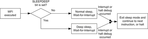
Whether the normal sleep mode or the deep sleep mode will be used is determined by a control bit called SLEEPDEEP. This bit is located in the System Control Register (SCR) of the System Control Block (SCB) region, which contains the control bits for the low-power features of the Cortex-M0 processor. Users of CMSIS-compliant device drivers can access to the System Control Register using the register name “SCB->SCR” (Table 11.2).
Different sleep modes and different sleep operation types can result in various combinations, as shown in Figure 11.4.

Wait-for-Event (WFE) and Wait-for-Interrupt (WFI)
There are two instructions that can cause the Cortex-M0 processor to enter sleep: WFE and WFI (Table 11.3). The WFE can be awakened by interrupt requests as well as events, whereas WFI can be awakened by interrupt requests or debug requests only.
Wait for Event (WFE)
When WFE is used to enter sleep, it can be awakened by interrupts or a number of events, including the following:
• New pending interrupts (only when the SEVONPEND bit in System Control Register is set)
• External event requests
• Debug events
Inside the Cortex-M0 processor, there is a single bit event register. When the processor is running, this register can be set to 1 when an event occurs, and this information is stored until the processor executes a WFE instruction. The event register can be set by any of the following events:
• The arrival of an interrupt request that needs servicing
• An exception entrance and exception exit
• New pending interrupts (only when SEVONPEND bit in System Control Register is set), even if the interrupts are disabled
• An external event signal from on-chip hardware (device specific)
• Execution of a Send Event (SEV) instruction
• Debug event
When multiple events occur while the processor is awake, they will be treated as just one event.
This event register is cleared when the stored event is used to wake up the processor from a WFE instruction. If the event register was set when the WFE instruction is executed, the event register will be cleared and the WFE will be completed immediately without entering sleep. If the event register was cleared when executing WFE, the processor will enter sleep, and the next event will wake up the processor, but the event register will remain cleared (Figure 11.5 and Figure 11.6).

The WFE is useful for reducing power in polling loops. For example, a peripheral with event generation function can work with the WFE so that the processor wakes up upon completion of peripheral's task. As shown in Figure 11.5 and Figure 11.6.

Because the processor can be awakened by different events, it must still check the peripheral status after being awakened to see if the task has completed.
If the SEVONPEND bit in the SCR is set, any new pending interrupts generate an event and wake up the processor. If an interrupt is already in pending state when the WFE is entered, a new interrupt request for the same interrupt does not cause the event to be generated and the processor will not be awakened.
Wait for Interrupt (WFI)
The WFI instruction can be awakened by interrupt requests that are a higher priority than the current priority level, or by debug requests (Figure 11.7).
There is one special case of WFI operation. During WFI sleep, if an interrupt is blocked by PRIMASK but otherwise has a higher priority than the current interrupt, it can still wake up the processor, but the interrupt handler will not be executed until the PRIMASK is cleared.
This characteristic allows software to turn off some parts of the microcontroller (e.g., the peripheral bus clock), and the software can turn it back on after waking up before executing the interrupt service routine.
Wakeup Conditions
When a WFI instruction is executed or when the processor enters sleep mode using the Sleep-on-Exit feature, the processor stops instruction execution and wakes up when a (higher priority) interrupt request arrives and needs to be serviced. If the processor enters sleep in an exception handler, and if the newly arrived interrupt request has the same or lower priority as the current exception, the processor will not wake up and will remain in a pending state. The processor can also be awakened by a halt request from debugger or by a reset.
When the WFE instruction is executed, the action of the processor depends on the current state of an event latch inside the processor:
• If the event latch was set, it will be cleared and the WFE completes without entering sleep.
• If the event latch was cleared, the processor will enter sleep mode until an event takes place.
An event could be any of the following:
• An interrupt request arriving that needs servicing
• Entering or leaving an exception handler
• A halt debug request
• An external event signal from on-chip hardware (device specific)
• If the Send-Event-on-Pend (SEVONPEND) feature is enabled and a new pending interrupt occurs
• Execution of the Send Event (SEV) instruction
The event latch inside the processor can hold an event that happened in the past, so an old event can cause the processor to wake up from a WFE instruction. Therefore, usually the WFE is used in an idle loop or polling loop, as it might or might not cause entering of sleep mode.
WFE can also be awakened by interrupt requests if they have a higher priority than the current interrupt's priority level or when there is a new pending interrupt request and the SEVONPEND bit is set. The SEVONPEND feature can wake up the processor from WFE sleep even if the priority level of the newly pended interrupt is at the same or lower level than the current interrupt. However, in this case, the processor will not execute the interrupt handler and will resume program execution from the instruction following the WFE.
The wakeup conditions of the WFE and WFI instructions are illustrated in Table 11.4.
The wake up behavior of Sleep-on-Exit is same as WFI sleep.
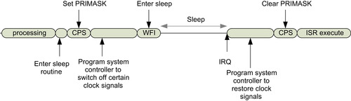
Some of you might wonder why when PRIMASK is set, it allows the processor to wake up but without executing the interrupt service routine (Figure 11.8). This arrangement allows the processor to execute system management tasks (for example, restore the clock to peripherals) before executing the interrupt service routine.
In summary, the differences between WFI and WFE included those described in Table 11.5.
Sleep-on-Exit Feature
One of the low-power features of the Cortex-M0 processor is the Sleep-on-Exit. When this feature is enabled, the processor automatically enters a Wait-for-Interrupt sleep mode when exiting an exception handler and if no other exception is waiting to be processed.
This feature is useful for applications where the processor activities are interrupt driven. For example, the software flow could be like the flowchart in Figure 11.9.
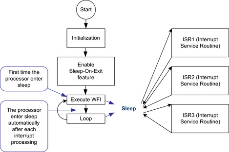
The resulting activities of the processor are illustrated in Figure 11.10.
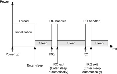
The Sleep-on-Exit feature reduces the active cycles of the processor and reduces the energy consumed by the stacking and unstacking of processes between the interrupts. Each time the processor finishes an interrupt service routine and enters sleep, it does not have to carry out the unstacking process because it knows that these registers will have to be stacked again when another interrupt request arrives next time.
The Sleep-on-Exit feature is controlled by the SLEEPONEXIT bit in the System Control Register. Setting this bit in an interrupt-driven application is usually carried out as the last step of the initialization process. Otherwise, if an interrupt occurs during this stage, the processor might enter sleep during the initialization of the processor.
Wakeup Interrupt Controller
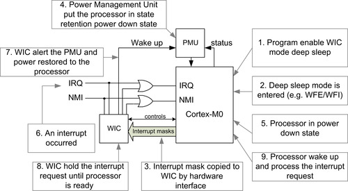
Designers of the Cortex-M0 microcontroller can optionally include a Wakeup Interrupt Controller (WIC) in their design. The WIC is a small interrupt detection logic that mirrors the interrupt masking function in the NVIC. The WIC allows the power consumption of the processor to be further reduced by stopping all the clock signals to the processor, or even putting the processor into a retention state. When an interrupt is detected, the WIC sends a request to a power management unit (PMU) in the microcontroller to restore power and clock signals to the processor, and then the processor can wake up and process the interrupt request.
The WIC itself does not contain any programmable registers; it has an interface that couples to the Cortex-M0 NVIC, and the interrupt mask information is transferred from the processor to the WIC automatically during sleep. The WIC is activated only in deep sleep mode (SLEEPDEEP bit is set), and you might also need to program additional control registers in the power management unit in the microcontroller to enable the WIC deep sleep mode.
The WIC enables the Cortex-M0 processor to reduce standby power consumption using a technology called State Retention Power Gating (SRPG). With SRPG, the leakage power of a sequential digital system during sleep can be minimized by powering off most parts of the logic, leaving a small memory element in each flip-flop to retain the current state. This is shown in Figure 11.11.

When working with the WIC, a Cortex-M0 processor implemented with SRPG technology can be powered down during deep sleep to minimize the leakage current of the microcontroller. During WIC mode deep sleep, the interrupt detection operation is handed over to the WIC (Figure 11.12). Because the state of the processor is retained in the flip-flops, the processor can wake up and resume operations almost immediately. In practice, the use of SRPG power down can increase the interrupt latency slightly, depending on how long it takes for the voltage on the processor to be stabilized after the power-up sequence.
Not all Cortex-M0 microcontrollers support the WIC feature. The reduction of power using the WIC depends on the application and the semiconductor process being used. When the WIC mode deep sleep is used, the SysTick timer is stopped and you might need to set up a separate peripheral timer to wake up the processor periodically if your application requires an embedded OS and needs the OS to operate continuously. Also, when developing simple applications without any embedded OS and if WIC mode deep sleep is required, use a peripheral timer for periodic interrupt generation instead of the SysTick timer.
..................Content has been hidden....................
You can't read the all page of ebook, please click here login for view all page.