
Chapter 19. Getting Started with the ARM RealView Development Suite
Overview
In addition to the ARM Keil Microcontroller Development Kit (MDK), ARM also provides another development suite called the RealView Development Suite (RVDS). Although it is based on the same C compiler, RVDS is targeted at the higher end of the market and has the following additional features:
• Supports all modern ARM processors including Cortex-A9/A8/A5
• RealView debugger provides multiprocessor debug support and full CoreSight debug support
• Offers profiler-driven compilation
• Supports Windows, Linux, and Unix
• Offers instruction set simulation (ISS) models
• Offers real-time system models (fast models)
When using RVDS, instead of targeting a microcontroller device, you target the compilation for a processor or ARM architecture version. This results in a number of differences between command line options in RVDS and Keil MDK. In this chapter, we will cover the basic steps of using RVDS to create your programs.
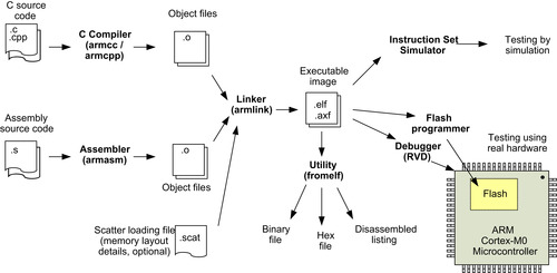
Typically, the software compilation flow using RVDS can be summarized as shown in Figure 19.1.
An integrated development environment (IDE) called the ARM Workbench IDE is included in RVDS. It is based in the open-source Eclipse IDE. You can also use RVDS either with the IDE or on the command line. In this chapter, we will focus mainly on the command line operation. Details of using the ARM Workbench IDE are covered in the ARM Workbench IDE User Guide (document DUI0330, reference 5). It can be downloaded from the ARM web site (http://informcenter.arm.com).
Simple Application Example
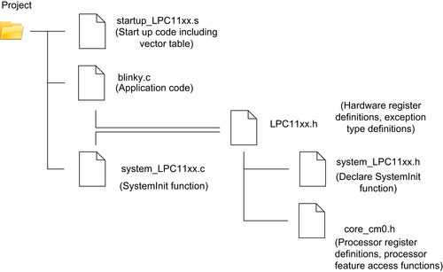
Using RVDS on the command line is straightforward. Based on the CMSIS version of the blinky example, we can compile the project with a few commands. First, we collect all the files necessary to build the application into a project folder. The folder named “Project” shown in Figure 19.2 is only an example; you can use other folder names.
In this example, we are going to reuse the program code from the previous Keil MDK projects for NXP LPC1114. If you have Keil MDK installed, you can find these files in the locations identified in Table 19.1.
| File | Location (assuming you have Keil MDK installed in C:KEIL) |
|---|---|
| startup_LPC11xx.s | C:KeilARMStartupNXPLPC11xx |
| system_LPC11xx.c | C:KeilARMStartupNXPLPC11xx, or Appendix H of this book |
| system_LPC11xx.h | C:KeilARMINCNXPLPC11xx, or Appendix H of this book |
| LPC11xx.h | C:KeilARMINCNXPLPC11xx |
| Blinky.c | See example code in Chapter 15 |
| core_cm0.h | C:KeilARMINC |
If you do not have Keil MDK software installed, you can download the required files from the NXP web site at http://ics.nxp.com/support/documents/microcontrollers/zip/code.bundle.lpc11xx.keil.zip. In addition, you can also download the generic CMSIS support files from www.onarm.com.
Once you have copied the files into the project (see the note on the include path that follows), we can compile the project with the following commands:
# Assemble startup code
armasm -g --cpu Cortex-M0 startup_LPC11xx.s -o startup_LPC11xx.o
# Compile application code
armcc -c -g --cpu Cortex-M0 blinky.c -o blinky.o -I c:keilarminc -I c:keilarminc
xpLPC11xx
# Compile system initialization code
armcc -c -g --cpu Cortex-M0 system_LPC11xx.c -o system_LPC11xx.o -I c:keilarminc -I c:keilarminc
xpLPC11xx
# Linking stage
armlink startup_LPC11xx.o system_LPC11xx.o blinky.o --ro-base 0x0 --rw_base 0x10000000 "--keep=startup_LPC11xx.o(RESET)" "--first=startup_LPC11xx.o(RESET)" --map --entry=Reset_Handler -o blinky.elf
# Generate disassembled listing for checking
fromelf -c blinky.elf –output=list.txt
In the preceding example, we used the files from Keil MDK directly by adding an include path using the “-I” option. In this way, we do not have to copy the files across to the local directory.
The commonly used options for the program generation flows in RVDS include those described in Table 19.2, Table 19.3, Table 19.4 and Table 19.5.
Additional details of the available command line options can be found in the following documents: (Note: These documents names are for RealView Development Suite 4.0. other version of RVDS might have different document names.)
• armasm: RealView Compilation Tools Assembler Guide
• armcc: RealView Compilation Tools Compiler User Guide
• armlink: RealView Compilation Tools Linker User Guide
• fromelf: RealView Compilation Tools Utilities Guide
All of these documents are automatically installed on your machine when you install RVDS, or alternatively you can find them on the ARM web site at http://informcenter.arm.com.
Apart from using a batch file (for Windows platforms) or shell scripts (for Linux/Unix platforms), users of Linux, UNIX, or Windows with Cygwin (or similar) environments can also create files to handle the compile process.
Using the Scatter Loading File
In the previous example, we used command line options to specify the address range of the read-only region (flash/ROM) and read-write region (RAM). This is fine for many simple projects. However, for applications with a more complex memory layout, or if you want to arrange the memory map in specific ways, a scatter loading file should be used to describe the layout of the memory system.
To use the scatter-loading feature, we use the --scatter option in armlink. Using the previous blinky example, we can convert the program generation flow to use scatter loading:
# Assemble startup code
armasm -g --cpu Cortex-M0 startup_LPC11xx.s -o startup_LPC11xx.o
armcc -c -g --cpu Cortex-M0 blinky.c -o blinky.o -I c:keilarminc -I c:keilarminc
xpLPC11xx
# Compile system initialization code
armcc -c -g --cpu Cortex-M0 system_LPC11xx.c -o system_LPC11xx.o -I c:keilarminc -I c:keilarminc
xpLPC11xx
# Linking stage
armlink startup_LPC11xx.o system_LPC11xx.o blinky.o --
scatter scatter.scat"--keep=startup_LPC11xx.o(RESET)" --entry Reset_Handler --map -o blinky.elf
# Generate disassembled listing for checking
fromelf -c -e -d -s blinky.elf --output=list.txt
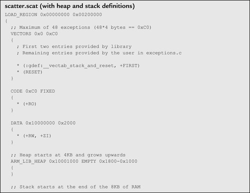
In this example, the scatter loading file we used is called scatter.scat:
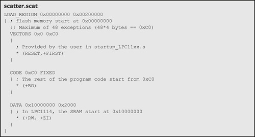 |
Using the scatter loading file, the “RESET” section in the startup code is allocated to the beginning of the memory. As a result, we do not need to use the --first option when running armlink. For systems with multiple ROM regions, you can add memory sections and assign different objects to different memory sections.
The scatter loading file can also be used to define stack memory and heap memory. This will be demonstrated in the next example when the vector table is coded in C. For this example, this step is not required because the stack and heap are defined in the startup code.
Details of scatter loading syntax can be found in the RealView Compilation Tools Developer Guide (reference 9).
Example with Vector Table in C
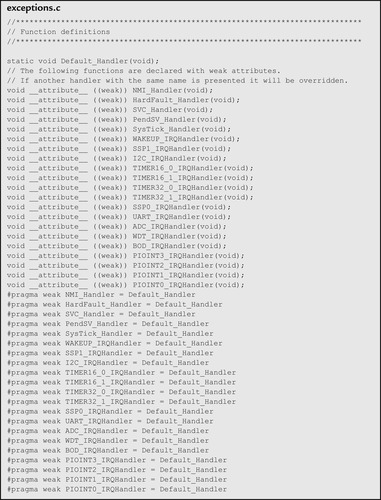
In the Keil MDK, the default startup codes for ARM microcontrollers are written in assembly. However, you can also create the vector table in C. In the following example, we will convert the blinky example to use a C vector table. Based on the exception vectors definition for NXP LPC1114, the following file “exceptions.c” is created:
 |
 |
 |
The C-based vector table in “exceptions.c” does not contain the initial stack pointer value and the reset vector. This will be inserted at the linking stage.
In the previous examples, the assembly startup code contains definitions for stack and heap memory. Because the C-based vector table does not contain such information, the scatter loading file is modified to include stack and heap memory definitions. The reset vector and initial stack pointer values are also defined in the scatter loading file.
 |
 |
With the vector table and the scatter loading file ready, we can generate the program image using the following command lines:
# Compile vector table and default handler
armcc -c -g --cpu Cortex-M0 exceptions.c -o exceptions.o
# Compile application code
armcc -c -g --cpu Cortex-M0 blinky.c -o blinky.o -I c:keilarminc -I c:keilarminc
xpLPC11xx
# Compile system initialization code
armcc -c -g --cpu Cortex-M0 system_LPC11xx.c -o system_LPC11xx.o -I c:keilarminc -I c:keilarminc
xpLPC11xx
armlink exceptions.o system_LPC11xx.o blinky.o --scatter scatter.scat "--keep=exceptions.o(RESET)"--map -o blinky.elf
# Generate disassembled listing for checking
fromelf -c -e -d -s blinky.elf --output=list.txt
Using MicroLIB in RVDS
In Keil MDK, one of the project options uses MicroLIB to reduce code size. MicroLIB is an implementation of the C library targeted specially for microcontroller applications where available program memory size could be limited. Because MicroLIB is optimized for small code size, the performance of the library functions is less than for the standard C library.
MicroLIB can also be used with RVDS. To demonstrate the use of MicroLIB, we use the RVDS blinky example and modify the program generation script to include the “--
library_type=microlib” option:
# Assemble start up code
armasm -g --cpu Cortex-M0 startup_LPC11xx.s -o startup_LPC11xx.o --library_type=microlib --pd "__MICROLIB SETA 1"
# Compile application code
armcc -c -g --cpu Cortex-M0 blinky.c -o blinky.o -I c:keilarminc -I c:keilarminc
xpLPC11xx --library_type=microlib
# Compile system initialization code
armcc -c -g --cpu Cortex-M0 system_LPC11xx.c -o system_LPC11xx.o -I c:keilarminc -I c:keilarminc
xpLPC11xx --library_type=microlib
# Linking stage
armlink startup_LPC11xx.o system_LPC11xx.o blinky.o "--keep=startup_LPC11xx.o(RESET)" "--first=startup_LPC11xx.o(RESET)" --entry Reset_Handler --rw_base 0x10000000 --map --ro-base 0x0 -o blinky.elf --library_type=microlib
# Generate disassembled listing for checking
fromelf -c blinky.elf --output=list.txt
In the assembly stage for the startup code, we added the additional option of --pd “__MICROLIB SETA 1.” This is because MicroLIB has different stack and heap definitions compared to the standard C library; as a result, the startup code contains the conditional assembly directive, controlled by the __MICROLIB option.
Using Assembly for Application Development in RVDS
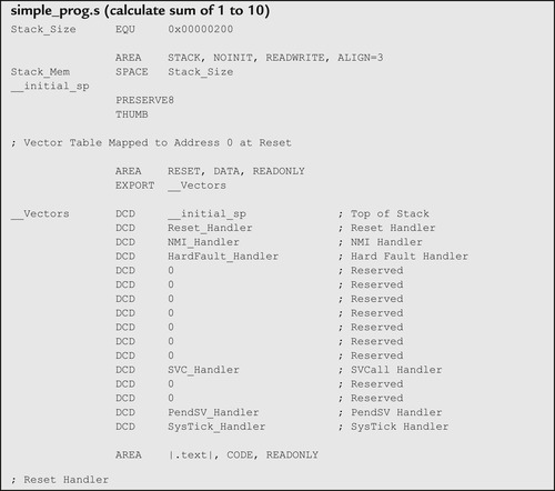
For small projects, it is possible to develop the entire project using assembler. For example, a program that calculates the sum of 1 to 10 can be as simple as that shown here:
 |
 |
The program combined the vector table, the main application code, some dummy exception handlers, and the stack definition. Because there is only one object file, there is no need to carry out a separate link stage. All you need to assemble the program and generate the execution image can be carried out in just one
armasm command:
# Generate executable image
armasm -g --cpu Cortex-M0 simple_prog.s -o simple_prog.elf
# Generate disassembled code for checking
fromelf -c simple_prog.elf --output=list.txt
For most applications, it is common to separate the vector table and the application code. For example, we can reuse the assembly version of the blinky example in Chapter 16 and assemble it using RVDS as follows:
# Assemble the vector table and startup code
armasm -g --cpu Cortex-M0 startup_LPC11xx.s -o startup_LPC11xx.o
# Assemble the application code
armasm -g --cpu Cortex-M0 blinky.s -o blinky.o
# Linking stage
armlink startup_LPC11xx.o blinky.o "--keep=startup_LPC11xx.o(RESET)" "--first=startup_LPC11xx.o(RESET)"--entry Reset_Handler --rw_base 0x10000000 --map --ro-base 0x0 -o blinky.elf
# Create disassembled list for checking
fromelf -c blinky.elf --output=list.txt
The general assembly programming techniques for RVDS are the same as in Keil MDK, which is covered in Chapter 16 3.
Flash Programming
After generating the compiled image, we often need to program the image into the flash memory of the microcontroller for testing. RVDS contains flash programming features for a number of ARM microcontroller devices. The details of using flash programming with RVDS are described in the ARM Workbench IDE User Guide. At the time of this writing, the RVDS installation (4.0-SP3) does not have flash programming support on the NXP LPC11xx product. However, you can create your own flash programming configuration files, and this topic is also covered in the ARM Workbench IDE User Guide (reference 5) and ARM Application Note 190, “Creating Flash Algorithms with Eclipse.”
Alternatively, there are a number of other solutions:
1. Using Keil MDK
• If you have access to Keil MDK and a supported in-circuit debugger (e.g., ULINK 2), you can use the flash programming feature in Keil MDK to program the image created in RVDS into the flash memory.
• To use Keil MDK to program on your image, you need to change the file extension from .elf to .axf.
• The next step is to create a μVision project in the same directory with the same name (e.g., blinky). In the project creation wizard, select the microcontroller device you use, and when asked to copy the default startup code, click “no” to prevent the existing file (if there is one) from being overwritten.
• Now you need to set the debug options to use your in-circuit debugger (e.g., ULINK 2) and flash programming option if necessary. By default the flash programming option should have been set up for you automatically.
• Once the execution image (with .AXF file extension) has been built, click the flash programming button on the toolbar
 . The compiled image will then be programmed into the flash memory.
• After the image is programmed in to the flash memory, you can start a debug session using the μVision debugger to debug your program.
2. Using other flash programming utilities
• Most ARM microcontrollers have flash programming utilities provided by the microcontroller vendors or other third parties. For example, the NXP LPC11xx microcontroller devices can be programmed using a tool called “Flash Magic,” provided by Embedded Systems Academy (www.flashmagictool.com). This tool works with the built-in flash memory programming firmware on the LPC11XX microcontroller devices and allows the device to be programmed with a serial communication connection.
Note that with the NXP LPC11xx series, the address 0x1C-0x1F in the flash memory is used as a checksum for the on-chip boot loader. Although flash memory programmers in Keil ULINK products handle this address automatically, third-party flash memory programmers may not be aware of this and might report an error when the programmed value and the read back value do not match. In version 4.10 and later of the Keil MDK, a utility called ELFDWT is included that can insert the checksum value in the generated AXF executable image. This allows all flash programmers supporting LPC11xx to use the created image. More information on the ELFDWT utility is covered in Chapter 14.
Debugging Using RealView Debugger
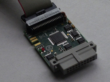
RVDS includes the RealView Debugger (RVD). To use RVD with a target system, you need to have a run-time control unit called RealView-ICE (Figure 19.3). The RealView-ICE ships with a standard 20-pin JTAG connector and can be connected to the debug host using either a USB or an Ethernet connection.

By default, RealView-ICE supports the JTAG debug protocol. To demonstrate the use of RVD with the Cortex-M0 with the JTAG debug protocol, here we use the Keil Microcontroller Prototyping System (MPS), a FPGA platform for prototyping Cortex-M systems, commonly used for system-on-chip or ASIC prototyping (Figure 19.4). (The existing NXP LPC11xx microcontrollers do not support JTAG debug.)

The MPS system contains two main FPGAs. One is for the processor and memory interface, and the other is a peripheral FPGA, which users can modify for SoC development. The processor FPGA can be switched between various Cortex-M processors including the Cortex-M0.
The MPS memory system contains 64 MB of flash memory and two SRAMs of 4 MB each. By default, the boot loader remaps one of the 4MB SRAMs to address 0x0 after it has been booted up so that users can download test code to SRAM and execute it from SRAM at high speed (zero wait state at 50 MHz).
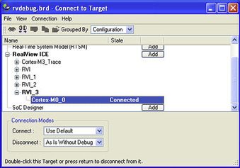
After launching RVD, you need to create a connection to the RealView ICE. Do this by accessing the Connect-to-Target function in the pull-down menu (Figure 19.5).

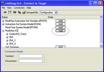
You can then add a connection configuration in the Connect-to-Target window (Figure 19.6).
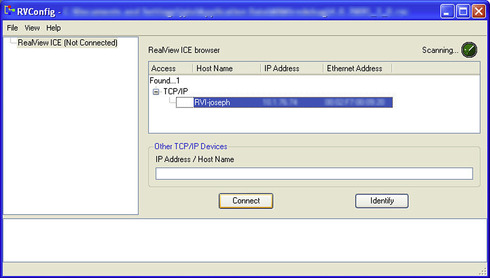
With RealView-ICE connected to your host personal computer (either by Ethernet or by USB), it will be detected in the RVconfig window (Figure 19.7).
After the RealView-ICE is connected, you can then use the Auto Configure function to detect the Cortex-M0 on the JTAG scan chain (Figure 19.8). We can then close the RVconfig window and save the configuration.

Back at the Connect-to-Target window, we can now expand the RealView ICE, locate the Cortex-M0 configuration, and connect to it by double-clicking on the Cortex-M0 connection (Figure 19.9). After the connection is made, the processor is put into a debug state and halts.
Before we load a compiled image and start debugging, we need to make the following adjustment: Click on the debug tab of the “Registers” windows, and change the reset type to “Ctrl_Reg.” This setting is used to control the reset being made by SYSRESETREQ rather than using the reset through the JTAG connection (Figure 19.10).

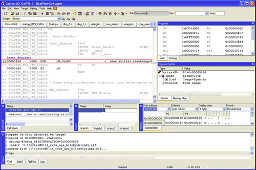
Now we are ready to load our compiled image into memory. This can be done by accessing the load image function in the pull-down menu: Target → Load image. The image is loaded and the program counter stops at the reset handler (Figure 19.11).
Now we are ready to run the program or debug using various features in RVD, including the following:
• Halting, single stepping, and restarting
• Processor registers accesses
• Memory examination (can be done without halting the processor)
• Breakpoint and watchpoint
In RVD, most of the debug operations can also be automated using scripts. For example, we can put the operations from changing the reset type to starting the program execution into a short script file called “blinky.inc” (script files in RVD normally have an “.inc” file extension).
// Change reset type to control register
setreg @Debug_RESETOPERATION=0x00000004
// Load file
load/r 'C:CortexM031_rvds_mps_blinkylinky.elf'
// Reset
reset
// start program execution
go
By creating this file, we can set up the system and get the program running by starting the script from the pull-down menu: choose Tools → Include commands from file, and then select the RVD script that we created.
Using Serial Wire Debug with the RealView Debugger
A serial wire debug interface can be used with the RVD and the RealView-ICE. However, this can only be achieved using an LVDS probe v2 (Figure 19.12). The 20-pin IDC connection cannot be used for serial wire debug operations. You also need RealView-ICE version 3.4 or later for serial wire debug operations.
To enable the serial wire debug operation, follow these steps:
• Connect the LVDS probe v2 to the JTAG B connector at the front of the RealView-ICE.
• You also need to update the LVDS probe by selecting “Update LVDS probe” in the RealView ICE Update utility (Figure 19.13).

• Reboot the RealView-ICE when the update has completed.
• Disconnect the RealView ICE Update utility from the RealView-ICE, and then start the RealView debugger.
• Create a new connection and connect to the RealView-ICE as shown in Figure 19.6
• In the RVConfig window, select “Advanced” settings; you will then find the serial wire debug option (as shown in Figure 19.14).
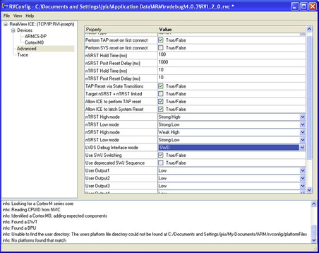
• Select SWD for LVDS Debug Interface mode (Figure 19.14). The use of the SWJ switching sequence is not essential for most Cortex-M0 devices. However, it is essential for most CortexM3 devices because the debug access port in most of the Cortex-M3 devices supports both JTAG and serial wire debug protocol, and JTAG protocol is used by default.
• Now you can connect to the Cortex-M0 using the serial wire debug interface (Figure 19.15).

Note that the first version of the LVDS probe cannot support serial wire debug.
Retargeting in RVDS
One of the advanced features available in RealView Debugger RVD is semihosting support. This allows I/O functions like “printf,” “scanf,” and even file operations like “fopen” and “fread” to be carried out via the debugger. For example, a small program that requests user inputs (“scanf”) and generates output messages (“printf”) can be compiled with RVDS and then tested with RVD though the StdIO console window.
To demonstrate, a simple “hello” program is created:
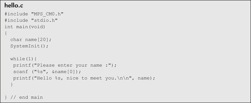 |
This program is then compiled with RVDS, without retargeting I/O through the UART.
When the program is executed in RVD, the StdIO console window will display the output message and allow us to input information (bottom of Figure 19.16).

Although it is possible to handle input output functions by setting up retargeting using UART, in some system-on-chip designs a UART interface might not be available. The semihosting support also allows data used for software testing to be stored on the debug host (personal computer) and accessed by the application running on the target system to access these files.
..................Content has been hidden....................
You can't read the all page of ebook, please click here login for view all page.