Chapter 21. Software Porting
Overview
As software reuse becomes more common, software porting is becoming a more common task for embedded software developers. In this chapter, we will look into differences between various common ARM processors for microcontrollers and what areas in a program need to be modified when porting software between them.
This chapter also covers software porting of software from 8-bit and 16-bit architectures.
ARM Processors
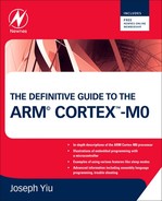
A number of ARM processors are used in microcontroller products (Table 21.1).
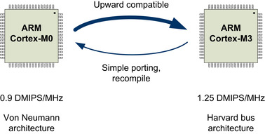
The main differences between the Cortex-M processors are illustrated in Figure 21.1.
In this chapter we will cover the detailed differences between the Cortex-M0 and some of these processors.
Differences between the ARM7TDMI and the Cortex-M0
There are a large number of differences between the ARM7TDMI and the Cortex-M0.
Operation Mode
The ARM7TDMI has a number of operation modes, whereas the Cortex-M0 only has two modes, as described in Table 21.2.
Some of the exception models from the ARM7TDMI are combined in Handler mode in the Cortex-M0 with different exception types. Consider the example presented in Table 21.3.
Registers
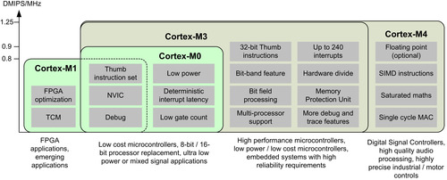
The ARM7TDMI has a register bank with banked registers based on current operation mode. In Cortex-M0, only the SP is banked (Figure 21.2). And in most simple applications without an OS, only the MSP is required.
There are some differences between the CPSR (Current Program Status Register) in the ARM7TDMI and the xPSR in the Cortex-M0. For instance, the mode bits in CPSR are removed, replaced by IPSR, and interrupt masking bit I-bit is replaced by the PRIMASK register, which is separate from the xPSR.
Despite the differences between the register banks, the programmer's model or R0 to R15 remains the same. As a result, Thumb instruction codes on the ARM7TDMI can be reused on the Cortex-M0, simplifying software porting.
Instruction Set
The ARM7TDMI supports the ARM instructions (32-bit) and Thumb instructions (16-bit) in ARM architecture v4T. The Cortex-M0 supports Thumb instructions in ARMv6-M, which is a superset of the Thumb instructions supported by the ARM7TDMI. However, the Cortex-M0 does not support ARM instructions. Therefore, applications for the ARM7TDMI must be modified when porting to Cortex-M0.
Interrupts
The ARM7TDMI supports an IRQ interrupt input and a Fast Interrupt (FIQ) input. Normally a separate interrupt controller is required in an ARM7TDMI microcontroller to allow multiple interrupt sources to share the IRQ and FIQ inputs. Because the FIQ has more banked registers and its vector is located at the end of the vector table, it can work faster by reducing the register stacking required, and the FIQ handler can be placed at the end of vector table to avoid branch penalty.
Unlike the ARM7TDMI, the Cortex-M0 has a built-in interrupt controller called NVIC with up to 32 interrupt inputs. Each interrupt can be programmed at one of the four available priority levels. There is no need to separate interrupts into IRQ and FIQ, because the stacking of registers is handled automatically by hardware. In addition, the vector table in the Cortex-M0 stores the starting address of each interrupt service routine, while in the ARM7TDMI the vector table holds instructions (usually branch instructions that branch to interrupt service routines).
When the ARM7TDMI receives an interrupt request, the interrupt service routine starts in ARM state (using ARM instruction). Additional assembly wrapper code is also required to support nested interrupts. In the Cortex-M0, there is no need to use assembly wrappers for normal interrupt processing.
Porting Software from the ARM7TDMI to the Cortex-M0
Application code for the ARM7TDMI must be modified and recompiled to be used on the Cortex-M0.
Startup Code and Vector Table
Because the vector table and the initialization sequence are different between the ARM7TDMI and the Cortex-M0, the startup code and the vector table must be replaced (Table 21.4).
Example of startup code for the Cortex-M0 can be found in various examples in this book.
Interrupt
Because the interrupt controller used in microcontrollers with the ARM7TDMI would be different from the NVIC in the Cortex-M0, all the interrupt control code needs to be updated. It is recommended to use the NVIC access functions defined in CMSIS for portability reason.
The interrupt wrapper function for nested interrupt support in the ARM7TDMI must be removed. If the interrupt service routine was written in assembly, the handler code will probably require rewriting because many ARM instructions cannot be directly mapped to Thumb instructions. For example, the exception handler in the ARM7TDMI can be terminated by “
MOVS PC, LR” (ARM instruction). This is not valid for the Cortex-M0 and must be replaced by “
BX LR”.
FIQ handlers for the ARM7TDMI might rely on the banked registers R8 to R14 in the ARM7TDMI to save execution time. For example, constants used by the FIQ handler might be preloaded into these banked registers before the FIQ is enabled so that the FIQ handle can be simplified. When porting such handlers to the Cortex-M0 processor, the banked registers are not available and therefore these constants must be loaded into the registers within the handler.
In some cases you might find assembly code being used to enable or disable interrupts by modifying the I-bit in CPSR. In the Cortex-M0, this is replaced by the PRIMASK interrupt masking register. Note that in the ARM7TDMI you can carry out the exception return and change the I-bit in a single exception return instruction. In the Cortex-M0 processor, PRIMASK and xPSR are separate registers, so if the PRIMASK is set during the exception handler, it must be cleared before the exception exit. Otherwise the PRIMASK will remain set and no other interrupt can be accepted.
C Program Code
Apart from the usual changes caused by peripherals, memory map, and system-level feature differences, the C applications might require changes in the following areas:
• For ARM RVDS or Keil MDK, all inline assembly has to be rewritten, either using embedded assembler, separate assembly code, or as C functions. Inline assembly in these tools only supports ARM instructions. Users of the GNU C compiler might also need to modify their inline assembly code.
• Exception handlers can be simplified because in the Cortex-M0, each interrupt has its own interrupt vector. There is no need to use software to determine which interrupt service is required, and there is no software overhead in supporting nested interrupts.
• Although the “__irq” directive is not essential in the Cortex-M0 exception handlers, this directive for interrupt handlers can be retained in ARM RVDS or Keil MDK projects for clarity. It might also help software porting if the application has to be ported to other ARM processors in the future.
The C code should be recompiled to ensure that only Thumb instructions are used and no attempt to switch to ARM state should be contained in the compiled code. Similarly, library files must also be updated to ensure they will work with the Cortex-M0.
Assembly Code
Because the Cortex-M0 does not support the ARM instruction set, assembly code that uses ARM instructions has to be rewritten.
Be careful with legacy Thumb programs that use the CODE16 directive. When the CODE16 directive is used, the instructions are interpreted as traditional Thumb syntax. For example, data processing op-codes without S suffixes are converted to instructions that update APSR when the CODE16 directive is used. However, you can reuse assembly files with the CODE16 directive because it is still supported by existing ARM development tools. For new assembly code, the THUMB directive is recommended, which indicates to the assembly that the Unified Assembly Language (UAL) is used. With UAL syntax, data processing instructions updating the APSR require the S suffix.
Fault handlers and system exception handlers like SWI must also be updated to work with the Cortex-M0.
Atomic Access
Because Thumb instructions do not support swap (SWP and SWPB instructions), the code for handling atomic access must be changed. For single processor systems without other bus masters, you can use either the exception mechanism or PRIMASK to achieve atomic operations. For example, because there can only be one instance of the SVC exception running (when an exception handler is running, other exceptions of the same or lower priority levels are blocked), you can use SVC as a gateway to handle atomic operations.
Optimizations
After getting the software working on the Cortex-M0, there are various areas you can look into to optimize your application code.
For assembly code migrated from the ARM7TDMI, the data type conversion operation is one of the potential areas for improvement because of new instructions available in the ARMv6-M architecture.
If the interrupt handlers were written in assembly, there might be chance that the stacking operations can be reduced because the exception sequence automatically stacks R0-R3 and R12.
More sleep modes features are available in the Cortex-M0 that can be used to reduce power consumption. To take the full advantages of the low-power features on a Cortex-M0 microcontroller, you will need to modify your application code to make use of the power management features in the microcontroller. These features are dependent on the microcontroller product, and the information in this area can usually be found in user manuals or application notes provided by the microcontroller vendors.
With the nested interrupts being automatically handled by processor hardware and the availability of programmable priority levels in the NVIC, the priority level of the exceptions can be rearranged for best system performance.
Differences between the Cortex-M1 and the Cortex-M0
Both the Cortex-M1 and the Cortex-M0 are based on the ARM architecture v6-M, so the differences between the Cortex-M1 and the Cortex-M0 are relatively small.
Instruction Set
In the Cortex-M1 processor, WFI, WFE and SEV instructions are executed as NOPs. There is no sleep feature on current implementations of the Cortex-M1 processor.
SVC instruction support is optional in the Cortex-M1 (based on the design configuration parameter defined by an FPGA designer), whereas in the Cortex-M0 processor, SVC instruction is always available.
NVIC
SVC and PendSV exceptions are optional in the Cortex-M1 processor. They are always present in the Cortex-M0. Interrupt latency are also different between the two processors. Some optimizations related in interrupt latency (e.g. zero jitter) are not available on the current implementations of Cortex-M1 processor.
System-Level Features
The Cortex-M1 has Tightly Coupled Memory (TCM) support to allow memory blocks in the FPGA to connect to the Cortex-M1 directly for high-speed access, whereas the Cortex-M0 processor has various low-power support features like WIC (Wakeup Interrupt Controller).
There are also a number of differences in the configuration options between the two processors. These options are only available for FPGA designers (for Cortex-M1 users) or ASIC designers (for Cortex-M0 microcontroller vendors). For example, with the Cortex-M1 processor you can include both the serial wire debug and the JTAG debug interface, whereas Cortex-M0 microcontrollers normally only support either the serial wire or the JTAG debug interface.
Porting Software between the Cortex-M0 and the Cortex-M1
In general, software porting between Cortex-M0 and Cortex-M1 is extremely easy. Apart from peripheral programming model differences, there are few required changes.
Because both processors are based on the same instruction set, and the architecture version is the same, the same software code can often be used directly when porting from one processor to another. The only exception is when the software code uses sleep features. Because the Cortex-M1 does not support sleep mode, application code using WFI and WFE might need to be modified.
There is also a small chance that the software needs minor adjustment because of execution timing differences.
At the time of writing, no CMSIS software package is available for the Cortex-M1. However, you can use the same CMSIS files for the Cortex-M0 on Cortex-M1 programming, because they are based on the same version of the ARMv6-M architecture.
Differences between the Cortex-M3 and the Cortex-M0
The Cortex-M3 processor is based on the ARMv7-M architecture. It supports many more 32-bit Thumb instructions and a number of extra system features. The performance of the Cortex-M3 is also higher than that for the Cortex-M0. These factors make the Cortex-M3 very attractive to demanding applications in the automotive and industrial control areas.
Programmer's Model
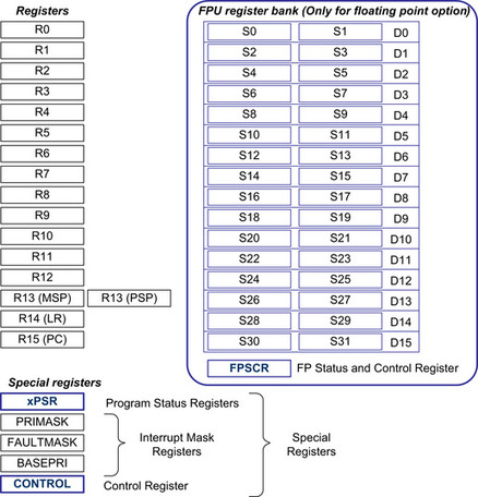
The ARMv7-M architecture is a superset of the ARMv6-M architecture. So it provides all the features available in the ARMv6-M. The Cortex-M3 processor also provides various additional features. For the programmer's model, it has an extra nonprivileged mode (User Thread) when the processor is not executing exception handlers. The user Thread mode access to the processor configuration registers (e.g., NVIC, SysTick) is restricted, and an optional memory protection unit (MPU) can be used to block programs running in user threads from accessing certain memory regions (Figure 21.3).

Apart from the extra operation mode, the Cortex-M3 also has additional interrupt masking registers. The BASEPRI register allows interrupts to of certain priority level or lower to be blocked, and the FAULTMASK provides additional fault management features.
The CONTROL register in the Cortex-M3 also has an additional bit (bit[0]) to select whether the thread should be in privileged or user Thread mode.
The xPSR in the Cortex-M3 also has a number of additional bits to allow an interrupted multiple load/store instruction to be resumed from the interrupted transfer and to allow an instruction sequence (up to four instructions) to be conditionally executed.
NVIC and Exceptions
The NVIC in the Cortex-M3 supports up to 240 interrupts. The number of priority levels is also configurable by the chip designers, from 8 levels to 256 levels (in most cases 8 levels to 32 levels). The priority level settings can also be configured into preemption priority (for nested interrupt) and subpriority (used when multiple interrupts of the same preempt priority are happening at the same time) by software.
One of the major differences between the NVIC in the Cortex-M3 and Cortex-M0 is that most of the NVIC registers in the Cortex-M3 can be accessed using word, half word, or byte transfers. With the Cortex-M0, the NVIC must be accessed using a word transfer. For example, if an interrupt priority register needs to be updated, you need to read the whole word (which consists of priority-level settings for four interrupts), modify 1 byte, and then write it back. In the Cortex-M3, this can be carried out using just a single byte-size write to the priority-level register. For users of the CMSIS device driver library, this difference does not cause a software porting issue, as the CMSIS NVIC access function names are the same and the functions use the correct access method for the processor.
The NVIC in the Cortex-M3 also supports dynamic changing of priority levels—in contrast to the Cortex-M0, where the priority level of an interrupt should not be changed after it is enabled.
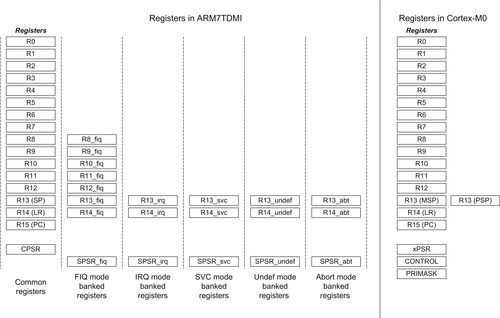
The Cortex-M3 has additional fault handlers with programmable priority levels. It allows the embedded systems to be protected by two levels of fault exception handlers (Figure 21.4).
When used together with the memory protection unit in the Cortex-M3, robust systems can be build for embedded systems that require high reliability.
The NVIC in the Cortex-M3 also supports the following features:
•
Vector Table Offset Register. The vector table can be relocated to another address in the CODE memory region or the SRAM memory region.
•
Interrupt Active Status Register. The active status of each interrupt can be determined by software.
• Additional fault status registers for indicating causes of fault exceptions and fault address
• An additional exception called the debug monitor for debug purposes.
Instruction Set
In addition to the Thumb instructions supported in the Cortex-M0 processor, the Cortex-M3 also supports a number of additional 16-bit and 32-bit Thumb instructions. These include the following:
• Signed and unsigned divide instructions (SDIV and UDIV)
• Compare and branch if zero (CBZ), compare and branch if not zero (CBNZ)
• IF-THEN (IT) instruction, allowing up to four subsequence instructions to be conditionally executed based on the status in APSR.
• Multiply and accumulate instructions for 32-bit and 64-bit results.
• Count leading zero (CLZ)
• Bit field processing instructions for bit order reversing, bit field insert, bit field clear, and bit field extract
• Table branch instructions (commonly used for the switch statement in C)
• Saturation operation instructions
• Exclusive accesses for multiprocessor environments
• Additional instructions that allows high registers (R8 and above) to be used in data processing, memory accesses, and branches
These additional instructions allow faster processing of complex data like floating point values. They also allow the Cortex-M3 to be used in audio signal processing applications, real time control systems.
System-Level Features
The Cortex-M3 includes a number of system-level features that are not available on the Cortex-M0. These include the following:
•
Memory protection unit (MPU). A memory access monitoring unit that provides eight memory regions. Each memory region can be defined with different locations and size, as well as different memory access permissions and access behavior. If an access violation is found, the access is blocked and a fault exception is triggered. The OS can use the MPU to ensure each task can only access permitted memory space to increase system reliability.
•
Unaligned memory accesses. In the Cortex-M0, all the data transfer operations must be aligned. This means a word-size data transfer must have an address value divisible by 4, and half-word data transfer must occur at even addresses. The Cortex-M3 processor allows many memory access instructions to generate unaligned transfers. On the Cortex-M0 processor, access of unaligned data has to be carried out by multiple instructions.
•
Bit band regions. The Cortex-M3 has two bit addressable memory regions called the bit-band regions. The first bit-band region is in the first 1 MB of the SRAM region, and the second one is the first 1 MB of the peripheral region. Using another memory address range called bit-band alias, the bit data in the bit band region can be individually accessed and modified.
•
Exclusive accesses. The Cortex-M3 supports exclusive accesses, which are used to handle shared data in multiprocessor systems such as semaphores. The processor bus interface supports additional signals for connecting to an exclusive access monitor unit on the bus system.
Debug Features
The Cortex-M3 provides additional breakpoints and data watchpoints in its debug system. The breakpoint unit can also be used to remap instruction or literal data accesses from the original address (e.g., mask ROM) to a different location in the SRAM region. This allows nonerasable program memories to be patched with a small programmable memory (Table 21.5).
| Cortex-M0 | Cortex-M3 | |
|---|---|---|
| Breakpoints | Up to 4 | Up to 8 |
| Watchpoints | Up to 2 | Up to 4 |
| Instruction trace | — | Optional |
| Data trace | — | Yes |
| Event trace | — | Yes |
| Software trace | — | Yes |
In addition to the standard debug features, the Cortex-M3 also has trace features. The optional Embedded Trace Macrocell (ETM) allows information about instruction execution to be captured so that the instruction execution sequence can be reconstructed on debugging hosts. The Data Watch-point and Trace (DWT) unit can be used to generate trace for watched data variables or access to memory ranges. The DWT can also be used to generate event trace, which shows information of exception entrance and exit. The trace data can be captured using a trace port analyzer such as the ARM RealView-Trace unit or an in-circuit debugger such as the Keil ULINK
Pro.
Porting Software between the Cortex-M0 and the Cortex-M3
Although there are a number of differences between the Cortex-M0 (ARMv6-M) and the Cortex-M3 (ARMv7-M), porting software between the two processors is usually easy. Because the ARMv7-M supports all features in the ARMv6-M, applications developed for the Cortex-M0 can work on the Cortex-M3 directly, apart from changes that result from their peripheral differences (Figure 21.5).
Normally, when porting an application from the Cortex-M0 to the Cortex-M3, you only need to change the device driver library, change the peripheral access code, and update the software for system features like clock speed, sleep modes, and the like.
Porting software from the Cortex-M3 to the Cortex-M0 might require more effort. Apart from switching the device driver library, you also need to consider the following areas:
• NVIC and SCB (System Control Block) registers in the Cortex-M0 can only be accessed in word-size transfers. If any program code accesses these registers in byte-size transfers or half-word transfers, they need to be modified. If the NVIC and SCB are accessed by using CMSIS functions, switching the CMSIS-compliant device driver to use the Cortex-M0 should automatically handle these differences.
• Some registers in the NVIC and the SCB in the Cortex-M3 are not available in the Cortex-M0. These include the Interrupt Active Status Register, the Software Trigger Interrupt Register, the Vector Table Offset Register, and some of the fault status registers.
• The bit-band feature in the Cortex-M3 is not available in the Cortex-M0. If the bit-band alias access is used, it needs to be converted to use normal memory accesses and handle bit extract or bit modification by software.
• If the application contains assembly code or embedded assembly code, the assembly code might require modification because some of the instructions are not available on the Cortex-M0. For C application code, some instructions such as hardware divide are not available in the Cortex-M0. In this case, the compiler will automatically call the C library to handle the divide operation.
• Unaligned data transfer is not available on the Cortex-M0.
• Some instructions available in the Cortex-M3 (e.g., exclusive accesses, bit field processing) are not available on the Cortex-M0.
Some Cortex-M0 microcontrollers support a memory remapping feature. Applications that use the vector table relocation feature on the Cortex-M3 might able to use the memory remapping feature to handle vector table relocation.
Applications that require the user Thread mode or the MPU feature cannot be ported to the Cortex-M0 because these features are not supported in the Cortex-M0.
Porting Software between the Cortex-M0 and the Cortex-M4 Processor
The Cortex-M4 processor is based on the same architecture as that used for the Cortex-M3. It is similar to the Cortex-M3 in many aspects: it has the same Harvard bus architecture, approximately the same performance in terms of Dhrystone DMIPS/MHz, the same exception types, and so on.
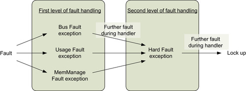
Compared to the Cortex-M3, the Cortex-M4 has additional instructions such as single instruction, multiple data (SIMD) instructions, saturation arithmetic instructions, data packing and extraction instructions, and optional single precision floating point instructions if a floating point unit is implemented. The floating point support in the Cortex-M4 is optional; therefore, not all Cortex-M4 microcontrollers will support this feature. If the floating point unit is included, it includes an additional floating point register bank and additional registers, as well as extra bit fields in the xPSR and CONTROL special registers (Figure 21.6). The floating point unit can be turned on or off by software to reduce power consumption.
Apart from these additional instructions, the system features of the Cortex-M4 are similar to those of the Cortex-M3 processor. Therefore, the techniques for porting software between the Cortex-M0 and the Cortex-M3 processors can also be used on porting software between the Cortex-M0 and Cortex-M4 processors. However, because of the differences between the nature of the two processors, some applications developed for the Cortex-M4 processor (e.g., high-end audio processing or industrial applications that require floating point operations) are unsuitable for the Cortex-M0 processor.
Porting Software from 8-Bit/16-Bit Microcontrollers to the Cortex-M0
Common Modifications
Some application developers might need to port applications from 8-bit or 16-bit microcontrollers to the Cortex-M0. By moving from these architectures to the Cortex-M0, often you can get better code density, higher performance, and lower power consumption.
When porting applications from these microcontrollers to the Cortex-M0, the modifications of the software typically involve the following:
•
Startup code and vector table. Different processor architectures have different startup code and interrupt vector tables. Usually the startup code and the vector table will have to be replaced.
•
Architecture-specific/tool-chain-specific C language extensions. Many of the C compilers for 8-bit and 16-bit microcontrollers support a number of C language extensions features. These include special data types like Special Function Registers (SFRs) and bit data in 8051, or various “
#pragma” statements in various C compilers.
•
Interrupt control. In 8-bit and 16-bit microcontroller programming, the interrupt configuration is usually done by directly writing to various interrupt control registers. When porting the applications to the ARM Cortex-M processor family, these codes should be converted to use the CMSIS interrupt control functions. For example, the enable and disable functions of interrupts can be converted to “
__enable_irq()” and “
__disable_irq()”. The configuration of individual interrupts can be handled by various NVIC functions in CMSIS.
•
Peripheral programming. In 8-bit and 16-bit microcontroller programming, the peripherals control is usually handled by programming to registers directly. When using ARM microcontrollers, many microcontroller vendors provide device driver libraries to make use of the microcontroller easier. You can use these library functions to reduce software development time or write to the hardware registers directly if preferred. If you prefer to program the peripherals by accessing the registers directly, it is still beneficial to use the header files in the device driver library as these have all the peripheral registers defined and can save you time preparing and validating the code.
•
Assembly code and inline assembly. Obviously all the assembly and inline assembly code needs to be rewritten. In many cases, you can rewrite the required function in C when the application is ported to the Cortex-M0.
•
Unaligned data. Some 8-bit or 16-bit microcontrollers might support unaligned data. Because the Cortex-M0 does not support unaligned data, some data structures definitions or pointer manipulation codes might need to be changed. For data structures that require unaligned data handling, we can use the
__packed attribute when defining the structure. However, the Cortex-M0 requires multiple instructions to access unaligned data. So it is best to convert the data structures so that all elements inside are aligned.
•
Be aware of data size differences. The integers in most 8-bit and 16-bit processors are 16-bit, whereas in ARM architectures integers are 32-bit. This difference causes changes in behavior of overflow situations, it can also affect the memory size required for storing the data. For example, when a program file defines an array of integers from 8-bit or 16-bit architecture, we might want to change the code to use “
short int” or “
int16_t” (in “stdint.h,” introduced in C99) when porting the code to ARM architecture so that the size remains unchanged.
•
Floating point. Many 8-bit and 16-bit microcontrollers define “
double” (double precision floating point) as 32-bit data. In ARM architecture, “
double” is 64-bit. When porting applications containing floating point operations, you might need to change the double precision floating point data to “
float” (single precision floating point). Otherwise the processing speed would be reduced and the program size could increase because of the requirement to process the data in extra precision. For the same reason, some function calls for mathematical operation might need to be changed to ensure that the single precision version is used. For example, by default “
cos()” is the double precision version of the
cosine function; for single precision operation, use “cosf()” instead.
•
Adding fault handlers. In many 8-bit and 16-bit microcontrollers, there are no fault exceptions. Although embedded applications can operate without any fault handlers, the addition of fault handlers can help an embedded system to recover from error (e.g., data corruption caused by voltage drop or electromagnetic interference).
Memory Requirements
One of the points mentioned earlier is the stack size. After porting to the ARM architecture, the required stack size could increase or decrease, depending on the application. The stack size might increase for the following reasons:
• Each register push takes 4 bytes of memory in ARM, whereas in 16-bit or 8-bit models, each register push takes 2 bytes or 1 byte.
• In ARM programming, local variables are often stored in stack, whereas in some architectures local variables might be defined in a separate data memory area.
On the other hand, the stack size could decrease for the following reasons:
• With 8-bit or 16-bit architecture, multiple registers are required to hold large data, and often these architectures have fewer registers compared to ARM, so more stacking would be required.
• The more powerful addressing mode in ARM means address calculations can be carried out on the fly without taking up register space. The reduction of register space used for an operation can reduce the stacking requirement.
Overall, the total RAM size required could decrease significantly after porting because in some architectures, such as the 8051, local variables are defined statically in data memory space rather on the stack. So the memory space is used even when the function or subroutine is not running. On the other hand, in ARM processors, the local variables allocated on the stack only take up memory space when the function or subroutine is executing. Also, with more registers available in the ARM processor's register bank compared to some other architectures, some of the local variables might only need to be stored in the register bank instead of taking up memory space.
The program memory requirement in the ARM Cortex-M0 is normally much lower than it is for 8-bit microcontrollers, and it is often lower than that required for most 16-bit microcontrollers. So when you port your applications from these microcontrollers to the ARM Cortex-M0 microcontroller, you can use a device with smaller flash memory size. The reduction of the program memory size is often caused by the following:
• Better efficiency at handling 16-bit and 32-bit data (including integers and pointers)
• More powerful addressing modes
• Some memory access instructions can handle multiple data, including PUSH and POP
There can be exceptions. For applications that contains only a small amount of code, the code size in ARM Cortex-M0 microcontrollers could be larger compared to that for 8-bit or 16-bit microcontrollers for a couple of reasons:
• The ARM Cortex-M0 might have a much larger vector table because of more interrupts.
• The C startup code for ARM Cortex-M0 might be larger. If you are using ARM development tools like the Keil MDK or the RealView Development Suite, switching to the MicroLIB might help to reduce the code size.
Nonapplicable Optimizations for 8-Bit or 16-it Microcontrollers
Some optimization techniques used in 8-bit/16-bit microcontroller programming are not required on ARM processors. In some cases, these optimizations might result in extra overhead because of architectural differences. For example, many 8-bit microcontroller programmers use character data as loop counters for array accesses:
unsigned char i; /∗ use 8-bit data to avoid 16-bit processing ∗/
char a[10], b[10];
for (i=0;i<10;i++) a[i] = b[i];
When compiling the same program on ARM processors, the compiler will have to insert a UXTB instruction to replicate the overflow behavior of the array index (“i”). To avoid this extra overhead, we should declare “
i” as integer “
int”, “
int32_t”, or “
uint32_t” for best performance.
Another example is the unnecessary use of casting. For example, the following code uses casting to avoid the generation of a 16 × 16 multiply operation in an 8-bit processor:
unsigned int x, y, z;
z = ((char) x) ∗ ((char) y); /∗ assumed both x and y must
be less than 256 ∗/
Again, such a casting operation will result in extra instructions in ARM architecture. Since Cortex-M0 can handle a 32 × 32 multiply with a 32-bit result in a single instruction, the program code can be simplified:
Example: Migrate from the 8051 to the ARM Cortex-M0
In general, because most applications can be programmed in C entirely on the Cortex-M0, the porting of applications from 8-bit/16-bit microcontrollers is usually straightforward and easy. Here we will see some simple examples of the modifications required.
Vector Table
In the 8051, the vector table contains a number of JMP instructions that branch to the start of the interrupt service routines. In some development environments, the compiler might create the vector table for you automatically. In ARM, the vector table contains the address of the main stack pointer initial values and starting addresses of the exception handlers. The vector table is part of the startup code, which is often provided by the development environment. For example, when creating a new project, the Keil MDK project wizard will offer to copy and add the default startup code, which contains the vector table (Table 21.6).
Data Type
In some cases, we need to modify the data type so as to maintain the same program behavior (Table 21.7).
| 8051 | Cortex-M0 |
|---|---|
| int my_data[20]; // array of 16-bit values
double pi; | short int my_data[20]; // array of 16-bit values
float pi; |
Some function calls might also need to be changed if we want to ensure only single precision floating point is used (Table 21.8).
| 8051 | Cortex-M0 |
|---|---|
| Y = T∗atan(T2∗sin(Y)∗cos(Y)/(cos(X+Y)+cos(X-Y)-1.0)); | Y = T∗atanf(T2∗sinf(Y)∗cosf(Y)/(cosf(X+Y)+cosf(X-Y)-1.0F)); |
Some special data types in 8051 are not available on the Cortex-M0: bit, sbit, sfr, sfr16, idata, xdata, and bdata.
Interrupt
Interrupt control code in 8051 are normally written as direct access to SFRs. They need to be changed to the CMSIS functions when ported to the ARM Cortex-M0. (Table 21.9).
The interrupt service routine also requires minor modifications. Some of the special directives used by the interrupt service routine need to be removed when the application code is ported to the Cortex-M0 (Table 21.10).
Sleep Mode
Entering of sleep mode is different too (Table 21.11). In 8051, sleep mode can be entered by setting the IDL (idle) bit in PCON. In the Cortex-M0, you can use the WFI instruction, or use vendor-specific functions provided in the device driver library.
..................Content has been hidden....................
You can't read the all page of ebook, please click here login for view all page.