Ladder and Functional Block Programming
Abstract
This chapter is an introduction to programming a PLC using ladder diagrams and functional block diagrams and their uses to represent basic switching operations involving the logic functions AND, OR, EXCLUSIVE OR, NAND and NOR, as well as latching. Programs involving such operations are developed.
Programs for microprocessor-based systems have to be loaded in machine code, a sequence of binary code numbers to represent the program instructions. However, assembly language based on the use of mnemonics can be used; for example, LD is used to indicate the operation required to load the data that follows the LD, and a computer program called an assembler is used to translate the mnemonics into machine code. Programming can be made even easier by the use of the so-called high-level languages, such as C, BASIC, Pascal, FORTRAN, and COBOL. These languages use prepackaged functions, represented by simple words or symbols descriptive of the function concerned. For example, with C language the symbol & is used for the logic AND operation. However, the use of these methods to write programs requires some skill in programming, and PLCs are intended to be used by engineers without any great knowledge of programming. As a consequence, ladder programming (LAD) was developed as a means of writing programs that can then be converted into machine code by software for use with the PLC microprocessor. This method of writing programs became adopted by most PLC manufacturers, but each tended to develop its own version, and so an international standard has been adopted for ladder programming and, indeed, all the methods used for programming PLCs. The standard, published in 1993, is IEC 61131-3 (see Section 1.4.2). Functional block programming (FBD) is another method of programming.
This chapter is an introduction to programming a PLC using ladder diagrams and functional block diagrams. Here we are concerned with the basic techniques involved in developing ladder and function block programs to represent basic switching operations involving the logic functions of AND, OR, EXCLUSIVE OR, NAND, and NOR, as well as latching. Later chapters continue with ladder programming involving other elements.
5.1 Ladder Diagrams
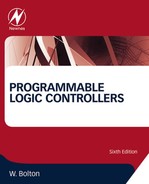
As an introduction to ladder diagrams, consider the simple wiring diagram for an electrical circuit in Figure 5.1a. The diagram shows the circuit for switching on or off an electric motor. We can redraw this diagram in a different way, using two vertical lines to represent the input power rails and stringing the rest of the circuit between them. Figure 5.1b shows the result. Both circuits have the switch in series with the motor and supplied with electrical power when the switch is closed. The circuit shown in Figure 5.1b is termed a ladder diagram.
With such a diagram, the power supply for the circuits is always shown as two vertical lines, with the rest of the circuit as horizontal lines. The power lines, or rails, as they are often called, are like the vertical sides of a ladder, with the horizontal circuit lines similar to the rungs of the ladder. The horizontal rungs show only the control portion of the circuit; in the case of Figure 5.1b it is just the switch in series with the motor. Circuit diagrams often show the relative physical location of the circuit components and how they are actually wired. With ladder diagrams, no attempt is made to show the actual physical locations, and the emphasis is on clearly showing how the control is exercised.
Figure 5.2 shows an example of a ladder diagram for a circuit that is used to start and stop a motor using push buttons. In the normal state, push button 1 is open and push button 2 closed. When button 1 is pressed, the motor circuit is completed and the motor starts. Also, the holding contacts wired in parallel with the motor close and remain closed as long as the motor is running. Thus when the push button 1 is released, the holding contacts maintain the circuit and hence the power to the motor. To stop the motor, push button 2 is pressed. This disconnects the power to the motor, and the holding contacts open. Thus when push button 2 is released, there is still no power to the motor. Thus we have a motor that is started by pressing button 1 and stopped by pressing button 2.

5.1.1 PLC Ladder Programming
A very commonly used method of programming PLCs is based on the use of ladder diagrams. Writing a program is then equivalent to drawing a switching circuit. The ladder diagram consists of two vertical lines representing the power rails. Circuits are connected as horizontal lines, that is, the rungs of the ladder, between these two verticals.
In drawing a ladder diagram, certain conventions are adopted:
• The vertical lines of the diagram represent the power rails between which circuits are connected. The power flow is taken to be from the left-hand vertical across a rung.
• Each rung on the ladder defines one operation in the control process.
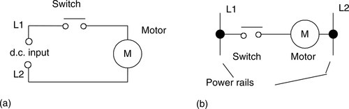
• A ladder diagram is read from left to right and from top to bottom. Figure 5.3 shows the scanning motion employed by the PLC. The top rung is read from left to right. Then the second rung down is read from left to right and so on. When the PLC is in its run mode, it goes through the entire ladder program to the end, the end rung of the program being clearly denoted, and then promptly resumes at the start (see Section 4.4). This procedure of going through all the rungs of the program is termed a cycle. The end rung might be indicated by a block with the word END or RET, for return, since the program promptly returns to its beginning. The scan time depends on the number of runs in the program, taking about 1 ms per 1000 bytes of program and so typically ranging from about 10 ms up to 50 ms.
• Each rung must start with an input or inputs and must end with at least one output. The term input is used for a control action, such as closing the contacts of a switch. The term output is used for a device connected to the output of a PLC, such as a motor. As the program is scanned, the outputs are not updated instantly, but the results stored in memory and all the outputs are updated simultaneously at the end of the program scan (see Section 4.6).
• Electrical devices are shown in their normal condition. Thus a switch that is normally open until some object closes it is shown as open on the ladder diagram. A switch that is normally closed is shown closed.
• A particular device can appear in more than one rung of a ladder. For example, we might have a relay that switches on one or more devices. The same letters and/or numbers are used to label the device in each situation.
• The inputs and outputs are all identified by their addresses; the notation used depends on the PLC manufacturer. This is the address of the input or output in the memory of the PLC (see Section 4.6).
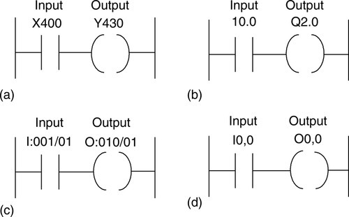
Figure 5.4 shows standard IEC 61131-3 symbols that are used for input and output devices. Some slight variations occur between the symbols when used in semigraphic form and when in full graphic, the semigraphic form being the one created by simply typing using the normal keyboard, whereas the graphic form is the result of using drawing tools. Note that inputs are represented by various symbols representing normally open or normally closed contacts. The action of the input is equivalent to opening or closing a switch. Output coils are represented by just one form of symbol. (More symbols are introduced in later chapters.) The name of the associated variable with its address is displayed directly above the symbol (for example, for an input start switch, X400, and for an output Motor 1, Y430).

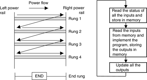
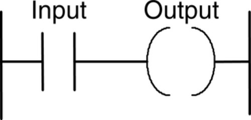
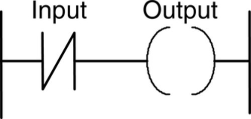
To illustrate the drawing of the rung of a ladder diagram, consider a situation where energizing an output device, such as a motor, depends on a normally open start switch being activated by being closed. The input is thus the switch and the output the motor. Figure 5.5a shows the ladder diagram. Starting with the input, we have the normally open symbol | | for the input contacts. There are no other input devices and the line terminates with the output, denoted by the symbol ( ). When the switch is closed, that is, there is an input, the output of the motor is activated. Only while there is an input to the contacts is there an output. If there had been a normally closed switch |/| with the output (Figure 5.5b), there would have been an output until that switch was opened. Only while there was no input to the contacts would there have been an output.
In drawing ladder diagrams, the names of the associated variable and addresses of each element are appended to its symbol. The more descriptive the name, the better, such as pump motor control switch rather than just input, and pump motor rather than just output. Thus Figure 5.6 shows how the ladder diagram of Figure 5.5a would appear using (a) Mitsubishi, (b) Siemens, (c) Allen-Bradley, and (d) Telemecanique notations for the addresses. Thus Figure 5.6a indicates that this rung of the ladder program has an input from address X400 and an output to address Y430. When connecting the inputs and outputs to the PLC, the relevant ones must be connected to the terminals with these addresses.
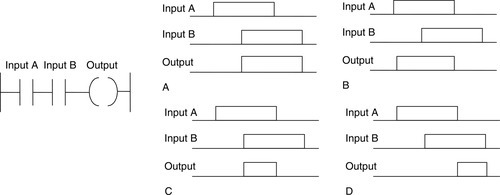
5.2 Logic Functions
There are many control situations requiring actions to be initiated when a certain combination of conditions is realized. Thus, for an automatic drilling machine (as illustrated in Figure 1.1a), there might be the condition that the drill motor is to be activated upon activation of the limit switches that indicate the presence of the workpiece and the drill position as being at the surface of the workpiece. Such a situation involves the AND logic function, condition A and condition B having both to be realized for an output to occur. This section is a consideration of such logic functions.
5.2.1 AND
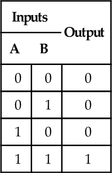
Figure 5.7a shows a situation in which an output is not energized unless two normally open switches are both closed. Switch A and switch B must both be closed, which thus gives an AND logic situation. We can think of this as representing a control system with two inputs, A and B (Figure 5.7b). Only when A and B are both on is there an output. Thus if we use 1 to indicate an on signal and 0 to represent an off signal, for there to be a 1 output, we must have A and B both 1. Such an operation is said to be controlled by a logic gate, and the relationship between the inputs to a logic gate and the outputs is tabulated in a form known as a truth table. Thus for the AND gate we have:
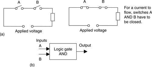
An example of an AND gate is an interlock control system for a machine tool so that it can only be operated when the safety guard is in position and the power switched on.
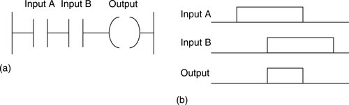
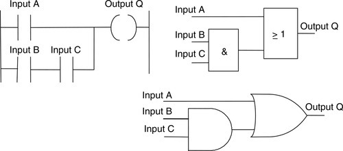
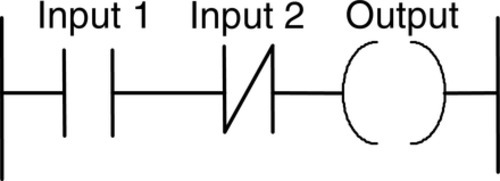
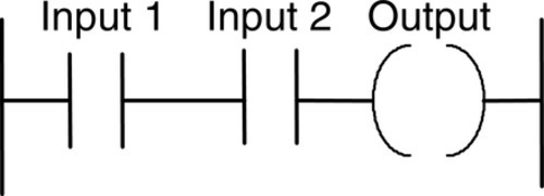
Figure 5.8a shows an AND gate system on a ladder diagram. The ladder diagram starts with | |, a normally open set of contacts labeled input A, to represent switch A and in series with it | |, another normally open set of contacts labeled input B, to represent switch B. The line then terminates with ( ) to represent the output. For there to be an output, both input A and input B have to occur, that is, input A and input B contacts have to be closed (Figure 5.8b). In general:
“On a ladder diagram, contacts in a horizontal rung, that is, contacts in series, represent the logical AND operations.”
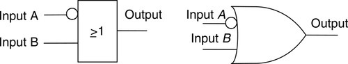
5.2.2 OR
Figure 5.9a shows an electrical circuit in which an output is energized when switch A or B, both normally open, are closed. This describes an OR logic gate (Figure 5.9b) in that input A or input B must be on for there to be an output. The truth table is as follows:


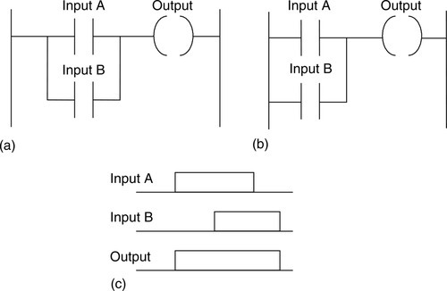
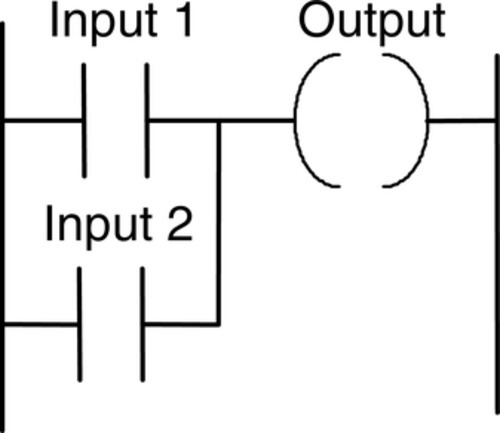
Figure 5.10a shows an OR logic gate system on a ladder diagram; Figure 5.10b shows an equivalent alternative way of drawing the same diagram. The ladder diagram starts with | |, normally open contacts labeled input A, to represent switch A and in parallel with it | |, normally open contacts labeled input B, to represent switch B. Either input A or input B must be closed for the output to be energized (Figure 5.10c). The line then terminates with ( ) to represent the output. In general:
“Alternative paths provided by vertical paths from the main rung of a ladder diagram, that is, paths in parallel, represent logical OR operations.”
An example of an OR gate control system is a conveyor belt transporting bottled products to packaging where a deflector plate is activated to deflect bottles into a reject bin if either the weight is not within certain tolerances or there is no cap on the bottle.
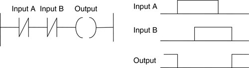
5.2.3 NOT
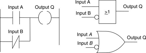
Figure 5.11a shows an electrical circuit controlled by a switch that is normally closed. When there is an input to the switch, it opens and there is then no current in the circuit. This example illustrates a NOT gate in that there is an output when there is no input and no output when there is an input (Figure 5.11c). The gate is sometimes referred to as an inverter. The truth table is as follows:
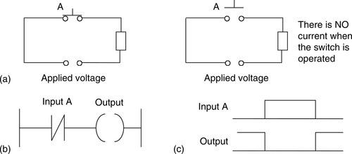

Figure 5.11b shows a NOT gate system on a ladder diagram. The input A contacts are shown as being normally closed. This input is in series with the output ( ). With no input to input A, the contacts are closed and so there is an output. When there is an input to input A, it opens and there is then no output.
An example of a NOT gate control system is a light that comes on when it becomes dark, that is, when there is no light input to the light sensor there is an output.
5.2.4 NAND
Suppose we follow an AND gate with a NOT gate (Figure 5.12a). The consequence of having the NOT gate is to invert all the outputs from the AND gate. An alternative that gives exactly the same result is to put a NOT gate on each input and then follow that with an OR gate (Figure 5.12b). The same truth table occurs, namely:
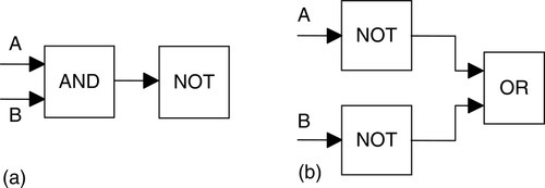

Either input A or input B (or both) have to be 0 for there to be a 1 output. There is an output when either input A or input B (or both) are not 1. The combination of these gates is termed a NAND gate.
Figure 5.13 shows a ladder diagram that gives a NAND gate. When either input A is 0 or input B is 0 (or both are 0), the output is 1. When the inputs to both input A and input B are 1, the output is 0.
An example of a NAND gate control system is a warning light that comes on if, with a machine tool, the safety guard switch and the limit switch signaling the presence of the workpiece have not been activated.
5.2.5 NOR
Suppose we follow an OR gate by a NOT gate (Figure 5.14a). The consequence of having the NOT gate is to invert the output of the OR gate. An alternative, which gives exactly the same results, is to put a NOT gate on each input and then an AND gate for the resulting inverted inputs (Figure 5.14b). The following is the resulting truth table:


The combination of OR and NOT gates is termed a NOR gate. There is an output when neither input A nor input B is 1.
Figure 5.15 shows a ladder diagram of a NOR system. When input A and input B are both not activated, there is a 1 output. When either input A or input B are 1, there is a 0 output.
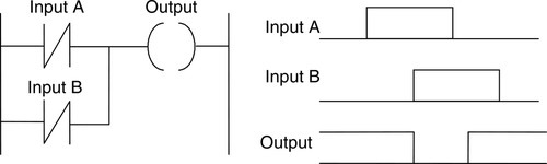
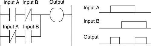
5.2.6 Exclusive OR (XOR)
The OR gate gives an output when either or both of the inputs are 1. However, sometimes there is a need for a gate that gives an output when either of the inputs is 1 but not when both are 1, that is, has the truth table:

Such a gate is called an EXCLUSIVE OR, or XOR, gate. One way of obtaining such a gate is by using NOT, AND, and OR gates as shown in Figure 5.16.

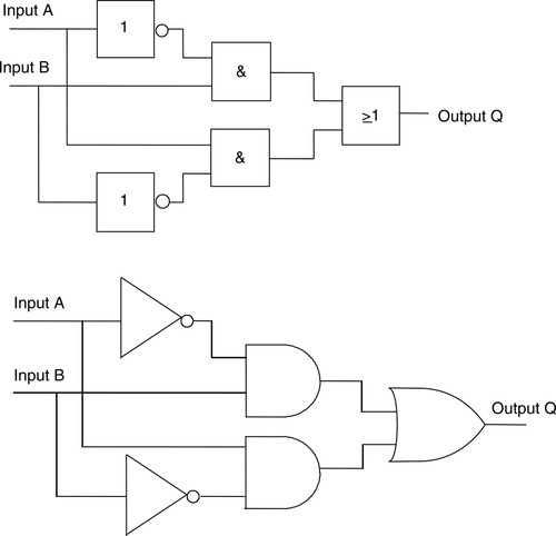
Figure 5.17 shows a ladder diagram for an XOR gate system. When input A and input B are not activated, there is 0 output. When just input A is activated, the upper branch results in the output being 1. When just input B is activated, the lower branch results in the output being 1. When both input A and input B are activated, there is no output. In this example of a logic gate, input A and input B have two sets of contacts in the circuits, one set being normally open and the other normally closed. With PLC programming, each input may be considered to have as many sets of contacts as necessary.
5.3 Latching
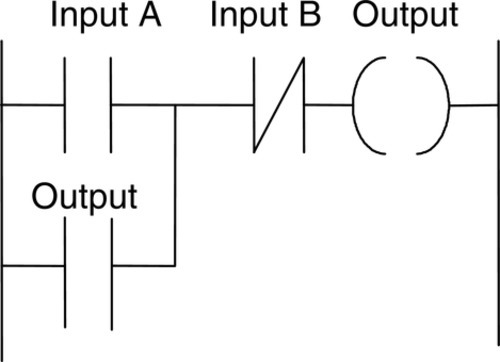
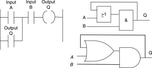
There are often situations in which it is necessary to hold an output energized, even when the input ceases. A simple example of such a situation is a motor that is started by pressing a push-button switch. Though the switch contacts do not remain closed, the motor is required to continue running until a stop push-button switch is pressed. The term latch circuit is used for the circuit that carries out such an operation. It is a self-maintaining circuit in that, after being energized, it maintains that state until another input is received.
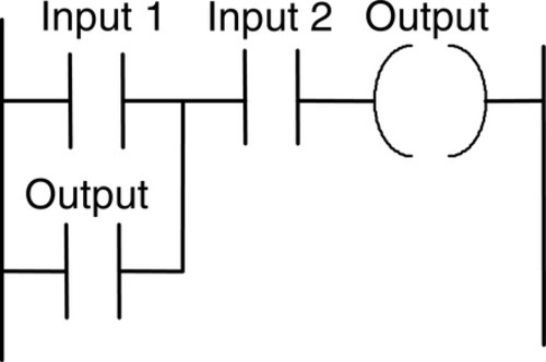
An example of a latch circuit is shown in Figure 5.18. When the input A contacts close, there is an output. However, when there is an output, another set of contacts associated with the output closes. These contacts form an OR logic gate system with the input contacts. Thus, even if input A opens, the circuit will still maintain the output energized. The only way to release the output is by operating the normally closed contact B.
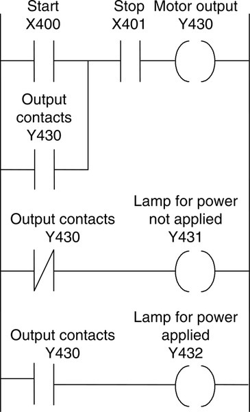
As an illustration of the application of a latching circuit, consider a motor controlled by stop and start push-button switches and for which one signal light must be illuminated when the power is applied to the motor and another when it is not applied. Figure 5.19 shows a ladder diagram with Mitsubishi notation for the addresses. X401 is closed when the program is started. When X400 is momentarily closed, Y430 is energized and its contacts close. This results in latching as well as the switching off of Y431 and the switching on of Y432. To switch the motor off, X401 is pressed and opens. Y430 contacts open in the top rung and third rung but close in the second rung. Thus Y431 comes on and Y432 goes off.
Latching is widely used with startups so that the initial switching on of an application becomes latched on.
5.4 Multiple Outputs
With ladder diagrams, there can be more than one output connected to a contact. Figure 5.20 shows a ladder program with two output coils. When the input contacts close, both the coils give outputs.

For the ladder rung shown in Figure 5.21, output A occurs when input A occurs. Output B occurs only when both input A and input B occur.
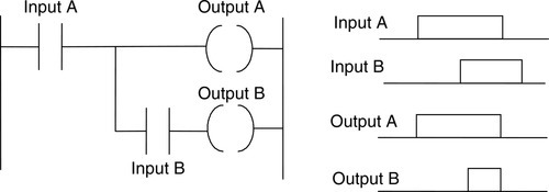
Such an arrangement enables a sequence of outputs to be produced, the sequence being in the sequence in which contacts are closed. Figure 5.22 illustrates this idea with the same ladder program in Mitsubishi and Siemens notations. Outputs A, B, and C are switched on as the contacts in the sequence given by the contacts A, B, and C are being closed. Until input A is closed, none of the other outputs can be switched on. When input A is closed, output A is switched on. Then, when input B is closed, output B is switched on. Finally, when input C is closed, output C is switched on.

5.5 Entering Programs
Each horizontal rung on the ladder represents an instruction in the program to be used by the PLC. The entire ladder gives the complete program. There are several methods that can be used for keying the program into a programming terminal. Whatever method is used to enter the program into a programming terminal or computer, the output to the memory of the PLC has to be in a form that can be handled by the microprocessor. This is termed machine language and is just binary code, such as 0010100001110001.
5.5.1 Ladder Symbols
One method of entering the program into the programming terminal involves using a keypad with keys with symbols depicting the various elements of the ladder diagram and keying them in so that the ladder diagram appears on the screen of the programming terminal. The terminal then translates the program drawn on the screen into machine language.
Computers can be used to draw up ladder programs. This involves loading the computer with the relevant software, such as RSLogix from Rockwell Automation Inc. for Allen-Bradley PLCs, MELSOFT−GX Developer for Mitsubishi PLCs, and STEP 7−Micro/WIN V4 for Siemens PLCs. The software operates on the Windows operating system and involves selecting items, in the usual Windows manner, from pull-down menus on the screen.
5.6 Function Blocks
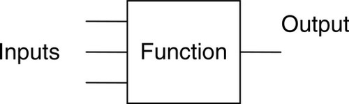
The term function block diagram (FBD) is used for PLC programs described in terms of graphical blocks. It is described as a graphical language for depicting signal and data flows through blocks, which are reusable software elements. A function block is a program instruction unit that, when executed, yields one or more output values. Thus a block is represented in the manner shown in Figure 5.23 with the function name written in the box.
The IEC 61113-3 standard for drawing such blocks is shown in Figure 5.24a. A function block is depicted as a rectangular block with inputs entering from the left and outputs emerging from the right. The function block type name is shown in the block, such as AND, with the name of the function block in the system shown above it, for example Timer1. Names of function block inputs are shown within the block at the appropriate input and output points. Cross-diagram connectors are used to indicate where graphical lines would be difficult to draw without cluttering up or complicating a diagram and show where an output at one point is used as an input at another. Figure 5.24b shows an example of a function block diagram.
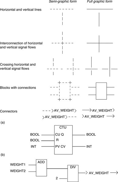
Function blocks can have standard functions, such as those of the logic gates, counters, or timers, or have functions defined by the user, such as a block to obtain an average value of inputs (Figure 5.24c).
5.6.1 Logic Gates
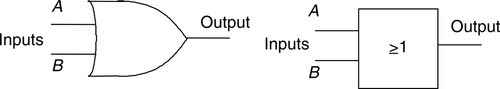
Programs are often concerned with logic gates. Two forms of standard circuit symbols are used for logic gates, one originating in the United States and the other an international standard form (IEEE/ANSI) that uses a rectangle with the logic function written inside it. The 1 in a box indicates that there is an output when the input is 1. The OR function is given by ≥1 because there is an output if an input is greater than or equal to 1. A negated input is represented by a small circle on the input, a negative output by a small circle on the output (Figure 5.25). Figure 5.26 shows the symbols. In FBD diagrams the notation used in the IEEE/ANSI form is often encountered.
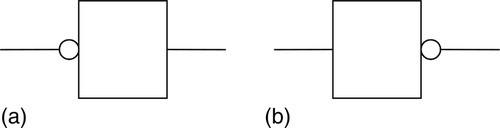
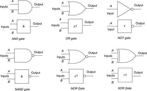
Figure 5.27 shows the effect of such functional blocks in PLC programs.

To illustrate the form of such a diagram and its relationship to a ladder diagram, Figure 5.28 shows an OR gate. When either the A or B input is 1, there is an output.

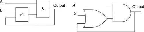
Figure 5.29 shows a ladder diagram and its function block equivalent in Siemens notation. The = block is used to indicate an output from the system.
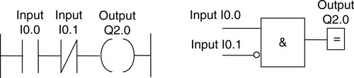
Figure 5.30 shows a ladder diagram involving the output with contacts acting as an input. The function block diagram equivalent can be shown as a feedback loop.
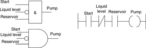
Consider the development of a function block diagram and ladder diagram for an application in which a pump is required to be activated and pump liquid into a tank when the start switch is closed, the level of liquid in the tank is below the required level, and there is liquid in the reservoir from which it is to be pumped. What is required is an AND logic situation between the start switch input and a sensor input that is on when the liquid in the tank is below the required level. We might have a switch that is on until the liquid is at the required level. These two elements are then in an AND logic situation with a switch indicating that there is liquid in the reservoir. Suppose this switch gives an input when there is liquid. The function block diagram and the equivalent ladder diagram are then of the form shown in Figure 5.31.
5.6.2 Boolean Algebra
Ladder programs can be derived from Boolean expressions since we are concerned with a mathematical system of logic. In Boolean algebra there are just two digits, 0 and 1. When we have an AND operation for inputs A and B, we can write:
where Q is the output. Thus Q is equal to 1 only when A = 1 and B = 1. The OR operation for inputs A and B is written as:
Thus Q is equal to 1 when A = 1 or B = 1. The NOT operation for an input A is written as:
Thus when A is not 1, there is an output.
As an illustration of how we can relate Boolean expressions with ladder diagrams, consider the expression:
This tells us that we have A or the term B and C giving the output Q. Figure 5.32 shows the ladder and functional block diagrams. Written in terms of Mitsubishi notation, the preceding expression might be:
In Siemens notation it might be:
As a further illustration, consider the Boolean expression:
Figure 5.33 shows the ladder and functional block diagrams. Written in terms of Mitsubishi notation, the expression might be:
and in Siemens notation:
Consider the XOR gate and its assembly from NOT, AND, and OR gates, as shown in Figure 5.34.
The input to the bottom AND gate is:
and so its output is:
The input to the top AND gate is:
and so its output is:
Thus the Boolean expression for the output from the OR gate is:
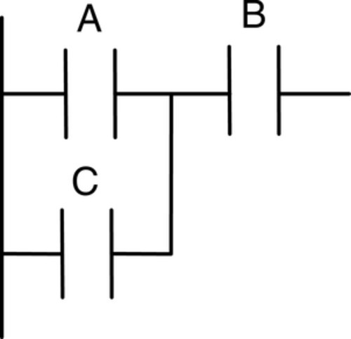
Consider a logic diagram with many inputs, as shown in Figure 5.35, and its representation by a Boolean expression and a ladder rung.
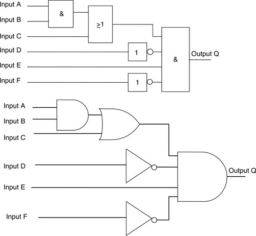
For inputs A and B we obtain an output from the upper AND gate of A·B. From the OR gate we obtain an output of A·B + C. From the lower AND gate we obtain an output Q of:
The ladder diagram to represent this idea is shown in Figure 5.36.
5.7 Program Examples
The following tasks illustrate the application of the programming techniques given in this chapter.
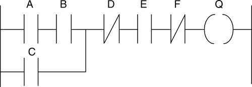
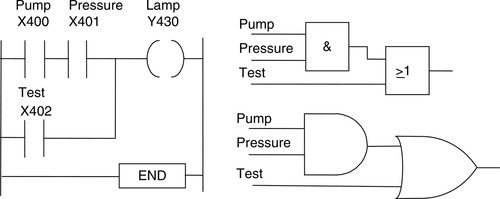
A signal lamp is required to be switched on if a pump is running and the pressure is satisfactory, or if the lamp test switch is closed. For the inputs from the pump and the pressure sensors, we have an AND logic situation, since both are required if there is to be an output from the lamp. However, we have an OR logic situation with the test switch in that it is required to give an output of lamp on, regardless of whether there is a signal from the AND system. The function block diagram and the ladder diagram are thus of the form shown in Figure 5.37. Note that with the ladder diagram, we tell the PLC when it has reached the end of the program by the use of the END or RET instruction.
As another example, consider a valve that is to be operated to lift a load when a pump is running and either the lift switch or a switch indicating that the load has not already been lifted and is at the bottom of its lift channel is operated. We have an OR situation for the two switches and an AND situation involving the two switches and the pump. Figure 5.38 shows a possible program.

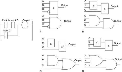
Next, consider a system where there has to be no output when any one of four sensors gives an output; otherwise there is to be an output. One way we could write a program for this situation is for each sensor to have contacts that are normally closed, so there is an output. When there is an input to the sensor, the contacts open and the output stops. Thus we have an AND logic situation. Figure 5.39 shows the functional block and ladder diagrams of a system that might be used.

5.7.1 Location of Stop Switches
The location of stop switches with many applications has to be very carefully considered to ensure a safe system. A stop switch is not safe if it is normally closed and has to be opened to give the stop action. If the switch malfunctions and remains closed, the system cannot be stopped (Figure 5.40a). It is better to program the stop switch in the ladder program as open in Figure 5.33b and use a stop switch that is normally closed and operating opens it. Thus there is an input signal to the system that closes the contacts in the program when it starts up.
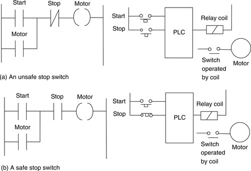
Figure 5.41 shows where we can safely locate an emergency stop switch. If it is in the input to the PLC (Figure 5.41a), then if the PLC malfunctions it might not be possible to stop the motor. However, if the emergency stop switch is in the output, operating it will stop the motor and cause the start switch to become unlatched if the arrangement shown in Figure 5.41b is being used. The motor will thus not restart when the emergency stop button is released.
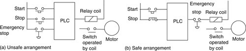
We must always have the situation that if a failure of the PLC occurs, the outputs must fall into a “fail-safe” state so that no harm can occur to anyone working in the plant.
Summary
Ladder programming (LAD) is a very common method of programming PLCs. Each rung on the ladder defines one operation in the control process and must start with an input or inputs and finish with at least one output. The program is scanned rung by rung, reading from left to right and finishing the cycle with the END rung. The program then restarts the cycle all over again. The inputs and outputs are all identified by their addresses. Rungs in ladder programs can be written to carry out the logic systems of AND, OR, NOT, NAND, NOR, and XOR with inputs. In latch programs, following an input, the output latches the input so that the output can continue even when the input has ceased. This is done by the output having a relay-type set of contacts that are activated when the output occurs and OR the input. Also, an input can be used to operate more than one output.
Function block diagrams (FBDs) can be used to program a PLC. Such programs are described as being a graphical language for depicting signal and data flows through blocks, which are reusable software elements. Logic gates are examples of such function blocks. Boolean algebra can be used to describe such programs.
Problems
Problems 1 through 19 have four answer options: A, B, C, or D. Choose the correct answer from the answer options.
1. Decide whether each of these statements is true (T) or false (F). Figure 5.42 shows a ladder diagram rung for which:
(i) The input contacts are normally open.
(ii) There is an output when there is an input to the contacts.
A. (i) T (ii) T
B. (i) T (ii) F
C. (i) F (ii) T
D. (i) F (ii) F
2. Decide whether each of these statements is true (T) or false (F). Figure 5.43 shows a ladder diagram rung for which:
(i) The input contacts are normally open.
(ii) There is an output when there is an input to the contacts.
A. (i) T (ii) T
B. (i) T (ii) F
C. (i) F (ii) T
D. (i) F (ii) F
3. Decide whether each of these statements is true (T) or false (F). Figure 5.44 shows a ladder diagram rung for which:
(i) When only input 1 contacts are activated, there is an output.
(ii) When only input 2 contacts are activated, there is an output.
A. (i) T (ii) T
B. (i) T (ii) F
C. (i) F (ii) T
D. (i) F (ii) F
4. Decide whether each of these statements is true (T) or false (F). Figure 5.45 shows a ladder diagram rung for which there is an output when:
(i) Inputs 1 and 2 are both activated.
(ii) Either input 1 or input 2 is activated.
A. (i) T (ii) T
B. (i) T (ii) F
C. (i) F (ii) T
D. (i) F (ii) F
5. Decide whether each of these statements is true (T) or false (F). Figure 5.46 shows a ladder diagram rung with an output when:
(i) Inputs 1 and 2 are both activated.
(ii) Input 1 or 2 is activated.
A. (i) T (ii) T
B. (i) T (ii) F
C. (i) F (ii) T
D. (i) F (ii) F
6. Decide whether each of these statements is true (T) or false (F). Figure 5.47 shows a ladder diagram rung for which there is an output when:
(i) Input 1 is momentarily activated before reverting to its normally open state.
(ii) Input 2 is activated.
A. (i) T (ii) T
B. (i) T (ii) F
C. (i) F (ii) T
D. (i) F (ii) F
Problems 7 through 10 refer to the following logic gate systems:
B. OR
C. NOR
D. NAND
7. Which form of logic gate system is given by a ladder diagram with a rung having two normally open sets of contacts in parallel?
8. Which form of logic gate system is given by a ladder diagram with a rung having two normally closed gates in parallel?
9. Which form of logic gate system is given by a ladder diagram with a rung having two normally closed gates in series?
10. Which form of logic gate system is given by a ladder diagram with a rung having two normally open gates in series?
Problems 11 through 14 concern Boolean expressions for inputs A and B.
A. Input A is in series with input B, both inputs being normally off.
B. Input A is in parallel with input B, both inputs being normally off.
C. Input A, normally off, is in series with input B, which is normally on.
D. Input A is in parallel with input B, both inputs being normally on.
11. Which arrangement of inputs is described by the Boolean relationship AċB?
12. Which arrangement of inputs is described by the Boolean relationship A + B?
13. Which arrangement of inputs is described by the Boolean relationship ![]()
14. Which arrangement of inputs is described by the Boolean relationship ![]()
15. The arrangement of inputs in Figure 5.48 is described by the Boolean expression:
B. (A + C)·B
C. (A + B)·C
D. A·C + B
16. Decide whether each of these statements is true (T) or false (F). For the function block diagram in Figure 5.49, there is an output:
(ii) When B is 1.
A. (i) T (ii) T
B. (i) T (ii) F
C. (i) F (ii) T
D. (i) F (ii) F
17. Decide whether each of these statements is true (T) or false (F). For the function block diagram in Figure 5.50, there is an output:
(ii) When B is 1.
A. (i) T (ii) T
B. (i) T (ii) F
C. (i) F (ii) T
D. (i) F (ii) F
18. Decide whether each of these statements is true (T) or false (F). For the functional block diagram in Figure 5.51, there is an output:

(i) When A is 1, B is 0 and C is 0.
(ii) When A is 0, B is 1 and C is 1.
A. (i) T (ii) T
B. (i) T (ii) F
C. (i) F (ii) T
D. (i) F (ii) F
19. Decide whether each of these statements is true (T) or false (F). For the function block diagram in Figure 5.52, with A being a steady input condition and B a momentary input, there is an output:
(ii) When A is 0 and B is 1.
A. (i) T (ii) T
B. (i) T (ii) F
C. (i) F (ii) T
D. (i) F (ii) F
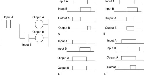
20. Figure 5.53 shows a ladder diagram. Which of the function block diagrams is its equivalent?
21. Figure 5.54 shows a function block diagram. Which of the ladder diagrams in Figure 5.54 is the equivalent?

22. Figure 5.55 shows a ladder diagram. Which of the diagrams showing inputs and output signals would occur with that ladder program?
23. Figure 5.56 shows a ladder diagram. Which of the diagrams showing inputs and output signals would occur with that ladder program?
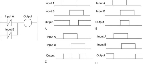
24. Figure 5.57 shows a ladder diagram. Which of the diagrams showing inputs and output signals would occur with that ladder program?
25. Draw the ladder rungs to represent:
(a) Two switches are normally open and both have to be closed for a motor to operate.
(b) Either of two, normally open, switches have to be closed for a coil to be energized and operate an actuator.
(c) A motor is switched on by pressing a spring-return push-button start switch, and the motor remains on until another spring-return push-button stop switch is pressed.
(d) A lamp is to be switched on if there is an input from sensor A or sensor B.
(e) A light is to come on if there is no input to a sensor.
(f) A solenoid valve is to be activated if sensor A gives an input.
(g) For safety reasons, machines are often set up to ensure that a machine can only be operated by the operator pressing two switches simultaneously, one by the right hand and one by the left hand. This is to ensure that both the operator's hands will be on the switches and cannot be in the machine when it is operating. Draw a ladder rung for such a requirement.
26. Draw the function block diagrams to represent:
(a) There is to be a motor startup when either switch A or switch B is activated.
(b) A motor is to be started when two normally open switches are activated and remain on, even if the first of the two switches goes off but not if the second switch goes off.
(c) A pump is to be switched on if the pump start switch is on or a test switch is operated.
27. Draw the ladder rungs represented by the Boolean equations:
(b) ![]()
(c) Q = A·B + C·D
28. Write the Boolean equations to represent the following:
(a) There is an output Q when either input A or input B occurs.
(b) There is an output Q when input A and input B occur but not when input C occurs.
(c) There is an output Q when input A occurs but not when input B occurs.
Lookup Tasks
29. Look up the specification of a PLC and the information given there concerning (a) scan time and (b) programming.