Counters
Counters are provided as built-in elements in PLCs and allow the number of occurrences of input signals to be counted. Some uses might include where items have to be counted as they pass along a conveyor belt, the number of revolutions of a shaft, or perhaps the number of people passing through a door. This chapter describes how such counters can be programmed.
10.1 Forms of Counter
A counter is set to some preset number value and, when this value of input pulses has been received, it will operate its contacts. Normally open contacts would be closed, normally closed contacts opened.
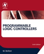
There are two basic types of counter: down-counters and up-counters. Down-counters count down from the preset value to zero, that is, events are subtracted from the set value. When the counter reaches the zero value, its contacts change state. Most PLCs offer down-counting. Up-counters count from zero up to the preset value, that is, events are added until the number reaches the preset value. When the counter reaches the set value, its contacts change state. Some PLCs offer the facility for both down- and up-counting. Figure 10.1 shows the IEC symbols for such counters.
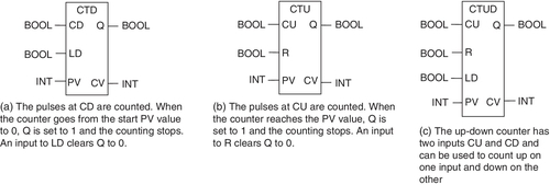
Different PLC manufacturers deal with counters in slightly different ways. Some count down (CTD) or up (CTU) and reset and treat the counter as though it is a relay coil and so a rung output. In this way, counters can be considered to consist of two basic elements: one relay coil to count input pulses and one to reset the counter, the associated contacts of the counter being used in other rungs. Figure 10.2a illustrates this method. Mitsubishi is one of the manufacturers that uses this method. Others treat the counter as an intermediate block in a rung from which signals emanate when the count is attained. Figure 10.2b illustrates this method, used by Siemens, among others.
10.2 Programming
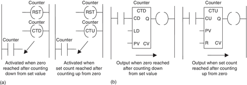
Figure 10.3 shows a basic counting circuit. Each time there is a transition from 0 to 1 at input In 1, the counter is reset. When there is an input to In 2 and a transition from 0 to 1, the counter starts counting. If the counter is set for, say, 10 pulses, then when 10 pulse inputs, that is, 10 transitions from 0 to 1, have been received at In 2, the counter's contacts will close and there will be an output from Out 1. If at any time during the counting there is an input to In 1, the counter will be reset, start all over again, and count for 10 pulses.
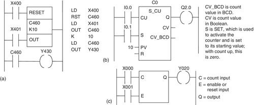
Figure 10.4a shows how the preceding program and its program instruction list would appear with a Mitsubishi PLC and a CTU counter. The reset and counting elements are combined in a single box spanning the two rungs. You can consider the rectangle to enclose the two counter ( ) outputs in Figure 10.3. The count value is set by a K program instruction. Figure 10.4b shows the same program with a Siemens PLC. With this ladder program, the counter is considered a delay element in the output line (as shown in Figure 10.1b). The counter is reset by an input to I0.1 and counts the pulses into input I0.0. The CU indicates that it is a up-count counter; a CD indicates a down-count counter. The counter set value is indicated by the LKC number. Figure 10.4c illustrates the program for a Toshiba PLC.
Figures 10.5a and 10.5b show the program for Allen-Bradley with up-count and down-count counters. The following are terms associated with such counters:
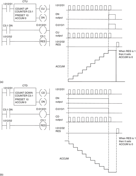
• The preset value (PRE) is the count value that the counter must accumulate before the counter output is 1.
• The accumulated value (ACC) is the accumulated number of 0 to 1 transitions of the counter rung. The count-up (CU) enable bit is 1 when the input logic makes the up-counter rung 1 and 0 when the rung is 0. The count-down (CD) enable bit is 1 when the input logic makes the down-counter rung 1 and 0 when the rung is 0.
• The done (DN) bit is 1 for both counters when the ACC value is equal to or greater than the PRE value and 0 when it is less.
• The count-up overflow (OV) bit is 1 when the up-counter increments above the maximum positive value.
• The count-down underflow (UN) bit is 1 when the counter decrements below the maximum negative value.
• Reset (RES) returns counter accumulator values to zero. As long as RES is 1, ACC and all output bits are held at 0. When RES is 0, the counter is able to start counting.
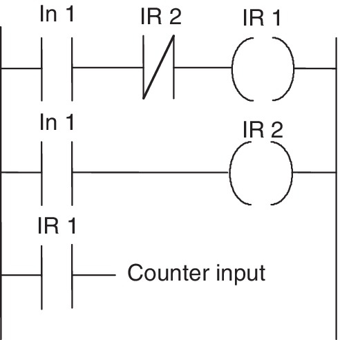
To ensure that the input pulses to a counter input are short duration, the ladder program shown in Figure 10.6 can be used. When there is an input to In 1, the internal relay IR 1 is activated; when the next rung is scanned a short while later, internal relay IR 2 is activated. When IR 2 is activated it switches off the input to IR 1. Thus IR 1 gives only a short duration pulse, which is then used as the input to a counter.
10.2.1 Counter Application
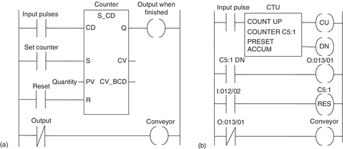
As an illustration of the use that can be made of a counter, consider the problem of items passing along a conveyor belt. The passage of an item past a particular point is registered by the interruption of a light beam to a photoelectric cell, and after a set number there is to be a signal sent informing that the set count has been reached and the conveyor stopped. Figure 10.7a shows the basic elements of a Siemens program that could be used. A reset signal causes the counter to reset and start counting again. The set signal is used to make the counter active. Figure 10.7b shows the basic elements of the comparable Allen-Bradley program. When the count reaches the preset value, the done bit is set to 1, and so O:013/01 occurs, the corresponding contacts are opened, and the conveyor stopped.
As a further illustration of the use of a counter, consider the problem of the control of a machine that is required to direct six tins along one path for packaging in a box and then 12 tins along another path for packaging in another box (Figure 10.8a). A deflector plate might be controlled by a photocell sensor that gives an output every time a tin passes it. Thus the number of pulses from the sensor has to be counted and used to control the deflector. Figure 10.8b shows the ladder program that could be used, with Mitsubishi notation.
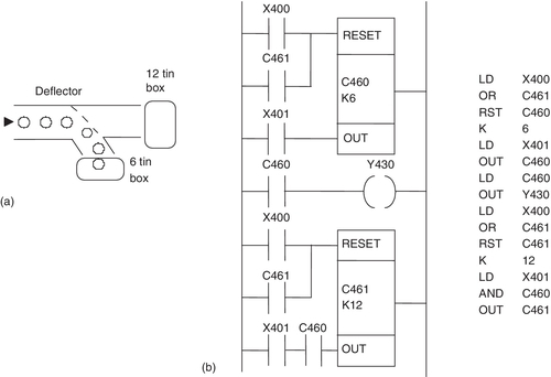
When there is a pulse input to X400, both the counters are reset. The input to X400 could be the push-button switch used to start the conveyor moving. The input that is counted is X401. This might be an input from a photocell sensor that detects the presence of tins passing along the conveyor. C460 starts counting after X400 is momentarily closed. When C460 has counted six items, it closes its contacts and so gives an output at Y430. This might be a solenoid that is used to activate a deflector to deflect items into one box or another. Thus the deflector might be in such a position that the first six tins passing along the conveyor are deflected into the six-pack box; then the deflector plate is moved to allow tins to pass to the 12-pack box. When C460 stops counting, it closes its contacts and so allows C461 to start counting. C461 counts for 12 pulses to X401 and then closes its contacts. This results in both counters being reset, and the entire process can repeat itself.
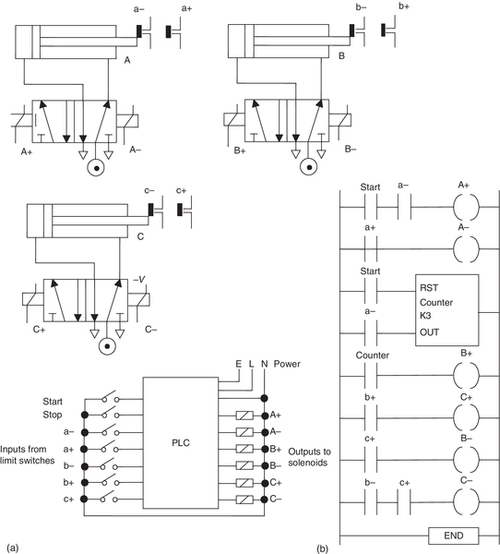
Counters can be used to ensure that a particular part of a sequence is repeated a known number of times. This is illustrated by the following program which is designed to enable a three-cylinder, double solenoid-controlled arrangement (Figure 10.9a) to give the sequence A+, A–, A+, A–, A+, A–, B+, C+, B–, C–. The A+, A– sequence is repeated three times before B+, C+, B–, C– occur. We can use a counter to enable this repetition. Figure 10.9b shows a possible program. The counter only allows B+ to occur after it has received three inputs corresponding to three a– signals.
10.3 Up- and Down-Counting
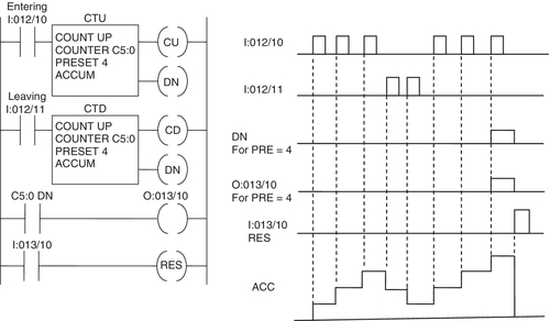
It is possible to program up- and down-counters together. Up-down counters are available as single entities; see Figure 10.1 for the IEC symbol. Consider the task of counting products as they enter a conveyor line and as they leave it, or perhaps cars as they enter a multistorage parking lot and as they leave it. An output is to be triggered if the number of items/cars entering is some number greater than the number leaving, that is, the number in the parking lot has reached a “saturation” value. The output might be to illuminate a “No empty spaces” sign. Suppose we use the up-counter for items entering and the down-counter for items leaving. Figure 10.10a shows the basic form a ladder program for such an application can take. When an item enters, it gives a pulse on input In 1. This increases the count by 1. Thus each item entering increases the accumulated count by 1. When an item leaves, it gives an input to In 2. This reduces the number by 1. Thus each item leaving reduces the accumulated count by 1. When the accumulated value reaches the preset value, the output Out 1 is switched on. Figure 10.10b shows how the preceding system might appear for a Siemens PLC and the associated program instruction list. CU is the count up input and CD the count down. R is the reset. The set accumulator value is loaded via F0.0, this being an internal relay.

Figure 10.11 shows the implementation of this program with an Allen-Bradley program and an up- and down-counter.
10.4 Timers with Counters
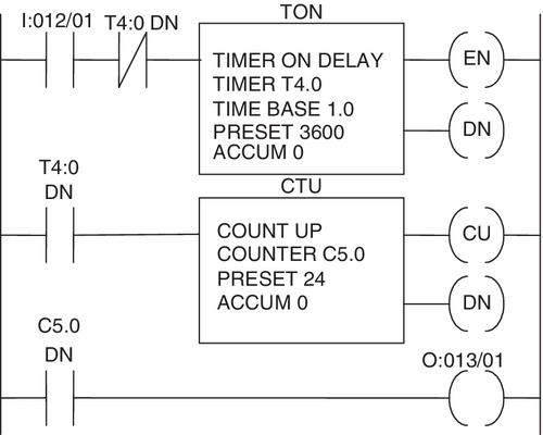
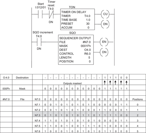
A typical timer can count up to 16 binary bits of data, this corresponding to 32,767 base time units. Thus, if we have a time base of 1 s, the maximum time that can be dealt with by a timer is just over 546 minutes, or 9.1 hours. If the time base is to be 0.1 s, the maximum time is 54.6 minutes, or just short of an hour. By combining a timer with a counter, longer times can be counted. Figure 10.12 illustrates this with an Allen-Bradley program. If the timer has a time base of 1 s and a preset value of 3600, it can count for up to 1 hour. When input I:012/01 is activated, the timer starts to time in 1-second increments. When the time reaches the preset value of 1 hour, the DN bit is set to 1 and the counter increments by 1. Setting the DN bit to 1 also resets the timer and the timer starts to time again. When it next reaches its preset time of 1 hour, the DN bit is again set to 1 and the counter increments by 1. With the counter set to a preset value of 24, the counter DN bit is set to 1 when the count reaches 24 and the output O:013/01 is turned on. We thus have a timer that is able to count the seconds for the duration of a day and would be able to switch on some device after 24 hours.
10.5 Sequencer
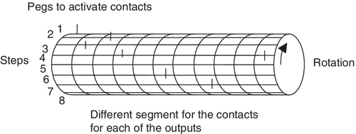
The drum sequencer is a form of counter that is used for sequential control. It replaces the mechanical drum sequencer that was used to control machines that have a stepped sequence of repeatable operations. One form of the mechanical drum sequencer consisted of a drum from which a number of pegs protruded (Figure 10.13). When the cylinder rotated, contacts aligned with the pegs were closed when the peg impacted them and opened when the peg had passed. Thus for the arrangement shown in Figure 10.13, as the drum rotates, in the first step the peg for output 1 is activated, in step 2 the peg for the third output, in step 3 the peg for the second output, and so on. Different outputs could be controlled by pegs located at different distances along the drum. Another form consisted of a series of cams on the same shaft, the profile of the cam being used to switch contacts on and off.
The PLC sequencer consists of a master counter that has a range of preset counts corresponding to the various steps; so as it progresses through the count, when each preset count is reached it can be used to control outputs. Each step in the count sequence relates to a certain output or group of outputs. The outputs are internal relays, which are in turn used to control the external output devices.
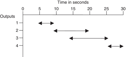
Suppose we want output 1 to be switched on 5 s after the start and remain on until the time reaches 10 s, output 2 to be switched on at 10 s and remain on until 20 s, output 3 to be switched on at 15 s and remain on until 25 s, and so on. We can represent these requirements by a time sequence diagram, shown in Figure 10.14, demonstrating the required time sequence.
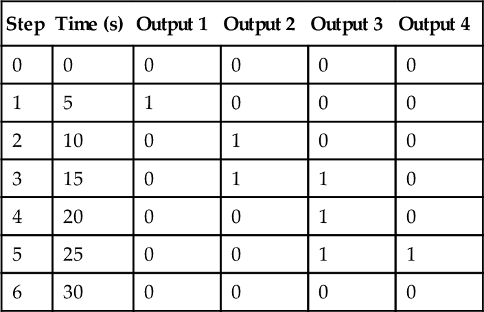
We can transform the timing diagram into a drum sequence requirement. Taking each drum sequence step to take 5 s gives the requirement diagram shown in Table 10.1. Thus at step 1 we require output 1 to be switched on and to remain on until step 2. At step 2 we require output 2 to be switched on and remain on until step 4. At step 3 we require output 3 to be switched on and remain on until step 5. At step 5 we require output 4 to be switched on and remain on until step 6.
Table 10.1
Sequence Requirements
| Step | Time (s) | Output 1 | Output 2 | Output 3 | Output 4 |
| 0 | 0 | 0 | 0 | 0 | 0 |
| 1 | 5 | 1 | 0 | 0 | 0 |
| 2 | 10 | 0 | 1 | 0 | 0 |
| 3 | 15 | 0 | 1 | 1 | 0 |
| 4 | 20 | 0 | 0 | 1 | 0 |
| 5 | 25 | 0 | 0 | 1 | 1 |
| 6 | 30 | 0 | 0 | 0 | 0 |
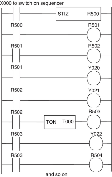
With a PLC such as a Toshiba, the sequencer is set up by switching on the Step Sequence Initialize (STIZ) function block R500 (Figure 10.15). This sets up the program for step 1 and R501. This relay then switches on output Y020. The next step is the switching on of R502. This switches on the output Y021 and a on-delay timer so that R503 is not switched on until the timer has timed out. Then R503 switches on Y022 as well as the next step in the sequence.
With the Allen-Bradley form of PLC the sequencer is programmed using a sequence of binary words in the form of the outputs required. The term sequencer output (SQO) is used by Allen-Bradley for the output instruction that uses a file or an array to control various output devices. Thus we might have the following binary word sequence entered into a file for each sequencer step using the programming device and so for six steps and five outputs in step 0 all of them would have the output 0, in step 1 output 1 would be 1 and the other outputs 0, in step 2 output 2 would be 1 and the other outputs 0, and so on.
Terms used with the sequencer are:
• File for the starting address for registers in the sequencer file, the indexed file indicator # being used for this address. Thus we might have #N7.0 the file for step 0 and so #N7.1 for step 1, #N7.2 for step 2, and so on.
• Mask for the bit pattern through which the sequencer instruction moves source data to the destination address. An h is placed behind the parameter to indicate the mask is an hexadecimal number or a B to indicate binary, decimal notation being entered without any indicator. Thus we might have 0001Fh which in binary is 0000 0000 0001 1111 and so allows the just the first five bits from the sequencer to be passed to the destination address all remaining bits being masked, i.e. not transmitted to the destination. As a further illustration we could have a mask word of 1110011011111110 and so, because bits 1, 9, 12, and 13 are 0, these bits in the sequencer words are not passed to the destination. Mask bit patterns are used as a means of selectively screening out data from the sequencer file for the required output.
• Destination is the address of the output word or file to which the instruction moves data from its sequencer file. Thus we might have O4.0 to indicate the output to which the output from step 1 goes.
• Control is the address that contains parameters with control information for the instruction and discrete outputs to indicate sequencer instruction results and status. The control file address is in control area R of the processor memory and the default file is 6.
• Length is the number of steps in in the sequencer file starting at step 1. As there is a step 0, the total number of words in the file is the length plus 1.
• Position is the word/step location in the sequencer file from or to which the instruction moves data. Thus if the position is 0 then after the first scan the position increments the position number by 1 and moves the sequencer file for that position number through the mask to the destination file.
As an illustration, Figure 10.16 shows a basic Allen-Bradley ladder program using such a sequencer. The timer is started by an input to I:012/1 and has a preset time of 30 s. It is reset by its DN bit. The DN bit also increments the SQO instruction to the next output word. Thus the sequencer is incremented every 30 s.
Summary
Counters are provided as built-in elements in PLCs and allow the number of occurrences of input signals to be counted. Down-counters count down from the preset value to zero, that is, events are subtracted from the set value. When the counter reaches the zero value, its contacts change state. Up-counters count from zero up to the preset value, that is, events are added until the number reaches the preset value. When the counter reaches the set value, its contacts change state. Some PLCs offer the facility for both down- and up-counting.
The PLC sequencer consists of a master counter that has a range of preset counts corresponding to the various steps; so as it progresses through the count, when each preset count is reached it can be used to control outputs.
Problems
Problems 1 through 19 have four answer options: A, B, C, or D. Choose the correct answer from the answer options. Problems 1 through 3 refer to Figure 10.17, which shows a ladder diagram with a down-counter, two inputs (In 1 and In 2), and an output (Out 1).
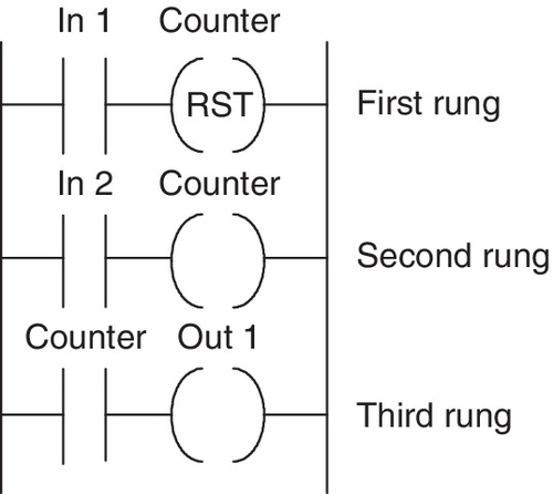
1. Decide whether each of these statements is true (T) or false (F). For the ladder diagram shown in Figure 10.17, when the counter is set to 5, there is an output from Out 1 every time:
(ii) In 2 has closed 5 times.
A. (i) T (ii) T
B. (i) T (ii) F
C. (i) F (ii) T
D. (i) F (ii) F
2. Decide whether each of these statements is true (T) or false (F). For the ladder diagram shown in Figure 10.17:
(i) The first rung gives the condition required to reset the counter.
(ii) The second rung gives the condition required to generate pulses to be counted.
A. (i) T (ii) T
B. (i) T (ii) F
C. (i) F (ii) T
D. (i) F (ii) F
3. Decide whether each of these statements is true (T) or false (F). In Figure 10.17, when there is an input to In 1:
(i) The counter contacts in the third rung close.
(ii) The counter is ready to start counting the pulses from In 2.
A. (i) T (ii) T
B. (i) T (ii) F
C. (i) F (ii) T
D. (i) F (ii) F
Problems 4 and 5 refer to the following program instruction list involving a down-counter:
4. Decide whether each of these statements is true (T) or false (F). Every time there is an input to X401:
(i) The count accumulated by the counter decreases by 1.
(ii) The output is switched on.
A. (i) T (ii) T
B. (i) T (ii) F
C. (i) F (ii) T
D. (i) F (ii) F
5. Decide whether each of these statements is true (T) or false (F). When there is an input to X400, the counter:
(ii) Starts counting from 0.
A. (i) T (ii) T
B. (i) T (ii) F
C. (i) F (ii) T
D. (i) F (ii) F
Problems 6 and 7 refer to the following program instruction list involving a counter C0:
6. Decide whether each of these statements is true (T) or false (F). Every time there is an input to I0.0:
(i) The count accumulated by the counter decreases by 1.
(ii) The output is switched on.
A. (i) T (ii) T
B. (i) T (ii) F
C. (i) F (ii) T
D. (i) F (ii) F
7. Decide whether each of these statements is true (T) or false (F). When there is an input to I0.1, the counter:
(ii) Starts counting from 0.
A. (i) T (ii) T
B. (i) T (ii) F
C. (i) F (ii) T
D. (i) F (ii) F
Problems 8 and 9 refer to Figure 10.18, which shows a down-counter C460 controlled by two inputs X400 and X401, with an output from Y430.
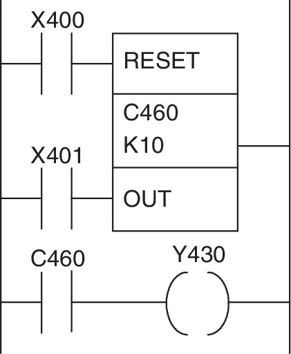
8. Decide whether each of these statements is true (T) or false (F). When there is an input to X400, the counter:
(ii) Starts counting.
A. (i) T (ii) T
B. (i) T (ii) F
C. (i) F (ii) T
D. (i) F (ii) F
9. Decide whether each of these statements is true (T) or false (F). Every time there is an input to X401, the counter:
(i) Gives an output from Y430.
(ii) Reduces the accumulated count by 1.
A. (i) T (ii) T
B. (i) T (ii) F
C. (i) F (ii) T
D. (i) F (ii) F
Problems 10 through 12 refer to Figure 10.19, which shows a ladder diagram involving a counter C460, inputs X400 and X401, internal relays M100 and M101, and an output Y430.
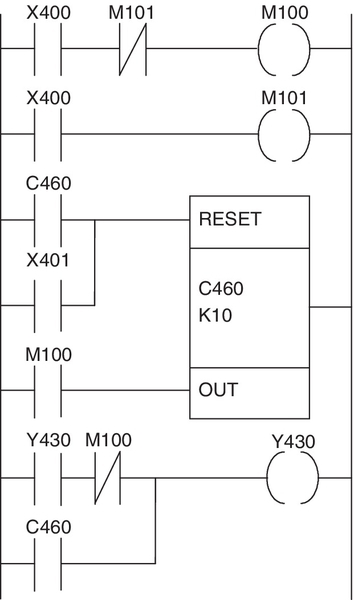
10. Decide whether each of these statements is true (T) or false (F). For the output Y430:
(i) It switches on with the tenth pulse to X400.
(ii) It switches off at the start of the eleventh pulse to X400.
A. (i) T (ii) T
B. (i) T (ii) F
C. (i) F (ii) T
D. (i) F (ii) F
11. Decide whether each of these statements is true (T) or false (F). When there is an input to X400:
(i) The internal relay M100 is energized.
(ii) The internal relay M101 is energized.
A. (i) T (ii) T
B. (i) T (ii) F
C. (i) F (ii) T
D. (i) F (ii) F
12. Decide whether each of these statements is true (T) or false (F). There is an output from Y430 as long as:
(i) The C460 contacts are closed.
(ii) Y430 gives an output and M100 is energized.
A. (i) T (ii) T
B. (i) T (ii) F
C. (i) F (ii) T
D. (i) F (ii) F
13. Decide whether each of these statements is true (T) or false (F). Figure 10.20 shows a counter program in Siemens format. After 10 inputs to I0.0:
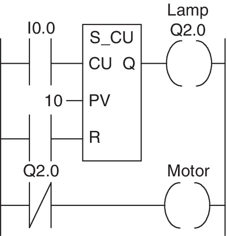
(ii) The motor starts.
A. (i) T (ii) T
B. (i) T (ii) F
C. (i) F (ii) T
D. (i) F (ii) F
Problems 14 and 15 refer to Figure 10.21, which shows a Siemens program involving an up- and down-counter.

14. Decide whether each of these statements is true (T) or false (F). When the count is less than 50 in Figure 10.21:
(i) There is an output from Q2.0.
(ii) There is an output from Q2.1.
A. (i) T (ii) T
B. (i) T (ii) F
C. (i) F (ii) T
D. (i) F (ii) F
15. Decide whether each of these statements is true (T) or false (F). When the count reaches 50 in Figure 10.21:
(i) There is an output from Q2.0.
(ii) There is an output from Q2.1.
A. (i) T (ii) T
B. (i) T (ii) F
C. (i) F (ii) T
D. (i) F (ii) F
Problems 16 and 17 refer to Figure 10.22, which shows an Allen-Bradley program involving a count-up counter.
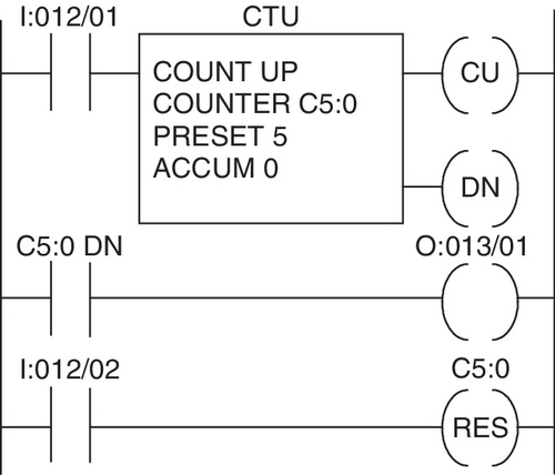
16. For the program shown in Figure 10.22, the counter is reset when:
B. The count passes 5.
C. There is an input to I:012/01.
D. There is an input to I:012/02.
17. Decide whether each of these statements is true (T) or false (F). For the program shown in Figure 10.22, there is an output at O:013/01 when:
(i) There is an input to I:012/01.
(ii) There is an output from the count-up done bit DN.
A. (i) T (ii) T
B. (i) T (ii) F
C. (i) F (ii) T
D. (i) F (ii) F
Problems 18 and 19 refer to Figure 10.23, which shows an Allen-Bradley program involving a count-up counter.
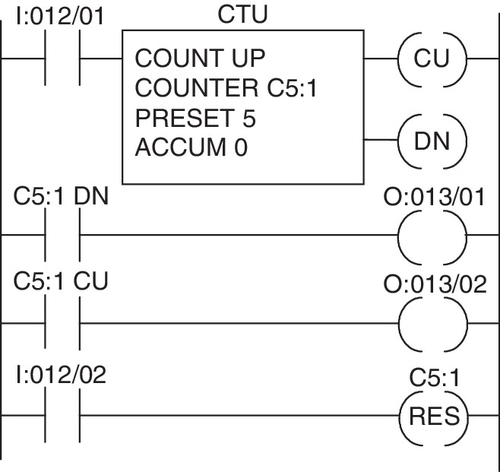
18. Decide whether each of these statements is true (T) or false (F). When there is a single pulse input to I:012/01 in Figure 10.23:
(i) Output O:013/01 is switched on.
(ii) Output O:013/02 is switched on.
A. (i) T (ii) T
B. (i) T (ii) F
C. (i) F (ii) T
D. (i) F (ii) F
19. Decide whether each of these statements is true (T) or false (F). When the fifth pulse input occurs to I:012/01 in Figure 10.23:
(i) Output O:013/01 is switched on.
(ii) Output O:013/02 is switched on.
A. (i) T (ii) T
B. (i) T (ii) F
C. (i) F (ii) T
D. (i) F (ii) F
20. Devise ladder programs for systems that will carry out the following tasks:
(a) Give an output after a photocell sensor has given 10 pulse input signals as a result of detecting 10 objects passing in front of it.
(b) Give an output when the number of people in a store reaches 100, there continually being people entering and leaving the store.
(c) Show a red light when the count is less than 5 and a green light when it is equal to or greater than 5.
(d) Count 10 objects passing along a conveyor belt and close a deflecting gate when that number have been deflected into a chute, allowing a time of 5 s between the tenth object being counted and closing the deflector.
(e) Determine the number of items on a conveyor belt at any particular time by counting those moving onto the belt and those leaving and give an output signal when the number on the belt reaches 100.
Lookup Tasks
21. Look up the counters available with a particular range of PLCs.
22. Select, from manufacturer's data sheets, possible sensors and a PLC that could be used to control the counting of nontransparent objects moving along a conveyor belt.