Answers
Chapter 1
2. A.
3. C.
4. A.
5. A.
6. C.
7. See Figure 1.4.
8. See Section 1.3.1.
9. 2 × 1024.
10. See Section 1.3.2 for an explanation of sourcing and sinking and 1.3.1 and Figure 1.15 for relay and transistor outputs.
Chapter 2
2. A.
3. B.
4. D.
5. C.
6. A.
7. A.
8. A.
9. B.
10. B.
11. C.
12. B.
13. C.
14. C.
15. See (a) Figure 2.6, (b) Section 2.1.4, (c) Section 2.1.3, (d) Section 2.1.8.
16. See Section 2.2.3.
17. See Section 2.2.4.
18. For example, (a) photoelectric transmissive system, (b) capacitive proximity sensor, (c) mechanical limit switch, (d) inductive proximity sensor.
19. See Section 2.2.4. Consider the behavior of RL circuits.
20. Stepper motor with 5° step.
21. (a) Photoelectric transmissive system, (b) direction control valve operated cylinder.
Chapter 3
2. (a) 110 0100, (b) 1001 0010, (c) 1111 1111.
3. (a) 159, (b) 3411, (c) 1660.
4. (a) E, (b) 51, (c) A02.
5. (a) 1110, (b) 11101, (c) 1010 0110 0101.
6. (a) 250, (b) 12, (c) 1376.
7. (a) 24, (b) 411, (c) 620.
8. (a) 010 111 000, (b) 001 000 010, (c) 110 111 011.
9. (a) 0010 0000, (b) 0011 0101, (c) 1001 0010.
10. (a) 1111 1111, (b) 1101 1101, (c) 1000 0011.
11. (a) −16, (b) −55, (c) −40.
12. (a) 0.110010 × 2−3, (b) 0.1100 × 2−4, (c) 0.1000 0100 × 24.
13. See Sections 3.7 and 3.8.
14. (a) 1 AND 1, (b) 1 OR 1, (c) 1 AND NOT 1.
15. D 1, CLK 1.
16. It is a D latch as in Table 3.4.
Chapter 4
2. D.
3. C.
4. B.
5. B.
6. A.
7. B.
8. A.
9. C.
10. C.
11. A.
12. C.
13. A.
14. D.
15. D.
16. (a) 0, (b) 1.
17. To detect message corruption.
18. See Section 4.5.
19. Input 1 kΩ, output 100 kΩ.
20. See Section 4.4.
21. See Sections (a) 4.5.5, (b) 4.5.2 and 4.5.3.
22. See Section 4.4.
Chapter 5
2. D.
3. B.
4. B.
5. B.
6. B.
7. B.
8. D.
9. C.
10. A.
11. A.
12. B.
13. D.
14. C.
15. B.
16. A.
17. C.
18. C.
19. D.
20. C.
21. A.
22. C.
23. A.
24. D.
25. See (a) Figure 5.8, (b) Figure 5.10, (c) Figure 5.19, (d) Figure 5.10, (e) Figure 5.11, (f) Figure 5.5(a), (g) an AND system as in Figure 5.8.
26. (a) An OR gate as in Figure 5.28, (b) as in Figure 5.30, (c) an OR gate as in Figure 5.28.
27. (a) As in Figure 5.33, (b) see Figure A.1(a), (c) see Figure A.1(b).
28. (a) Q = A + B, (b) ![]() , (c)
, (c) ![]() .
.
Chapter 6
2. A.
3. B.
4. D.
5. A.
6. C.
7. A.
8. B.
9. D.
10. A.
11. A.
12. C.
13. D.
14. B.
15. A.
16. B.
17. A.
18. C.
19. A.
20. D.
21. C.
22. A.
23. C.
24. B.
25. See Figure A.2.
26. WHILE NOT (Level_switch1 AND Drain_valve)
END_WHILE
27. CASE temperature_setting OF
1 : temp :=40;
2 : temp :=50;
3 ; temp :=60; fan1 :=1;
4 : temp :=70; fan2 :=1;
ELSE
Furnace:switch :=0;
END_Case
Chapter 7
2. B.
3. C.
4. A.
5. C.
6. C.
7. C.
8. B.
9. A.
10. A.
11. C.
12. D.
13. B.
14. B.
15. B.
16. C.
17. A.
18. A.
19. A.
20. B.
21. A.
22. A.
23. A.
23. B.
24. See (a) Figure 7.8, (b) Figure 7.9 or 7.10, (c) Figure 7.22.
Chapter 8
2. B
3. A
4. B
5. B
6. A
7. Call and return subroutines, which are blocks of program code; see Section 8.2.
Chapter 9
2. A.
3. D.
4. D.
5. D.
6. D.
7. C.
8. C.
9. B.
10. C.
11. A.
12. A.
13. A.
14. B.
15. D.
16. B.
17. A.
18. D.
19. C.
20. D.
21. B.
22. See (a) Figure 9.4, (b) Figure 9.10, (c) Figure 9.12, (d) see Figure A.3.
Chapter 10
2. A.
3. C.
4. B.
5. B.
6. B.
7. B.
8. D.
9. C.
10. A.
11. A.
12. B.
13. B.
14. C.
15. B.
16. D.
17. C.
18. C.
19. A.
20. See (a) Figure 10.4, (b) Figure 10.10, (c) see Figure A.4(a), (d) see Figure A.4(b), (e) similar to Figure 10.10 or 10.11.
Chapter 11
2. C.
3. C.
4. D.
5. A.
6. A.
7. C.
8. C.
9. D.
10. (a) As Figure 11.1/11.2 with a constant input to In 1/X400, so entering a 1 at each shift, (b) as in Figure 11.3 but instead of a faulty item, a hook with an item, and instead of a good item, hooks with no items.
Chapter 12
2. C.
3. B.
4. B.
5. A.
6. A.
7. B.
8. B.
9. C.
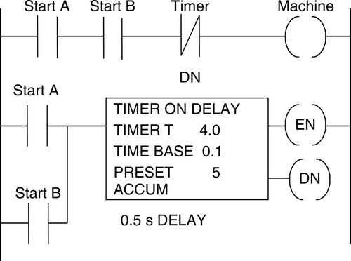
10. Similar to (a) Figure 12.5, (b) Figure 12.6, (c) see Figure A.5a, (d) see Figure A.5b.

11. See Section 12.4.
12. See Section 12.4.
Chapter 13
2. B.
3. C.
4. B.
5. C.
6. A.
7. A.
8. See Section 13.3.1.
9. Power failure, supply off, power tripped.
10. Wiring fault, device fault.
11. See Figure A.6.
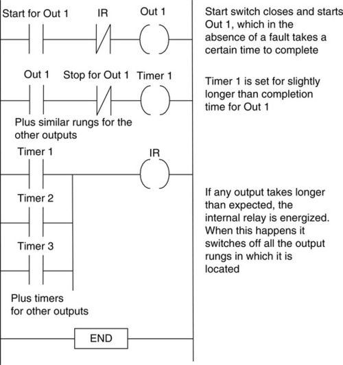
12. See Figure A.7.

Chapter 14
1. See Figure A.8.
2. See Figure A.9.
3. See Figure A.10 for a basic answer.
4. Hardwired emergency stop button, not dependent on software.
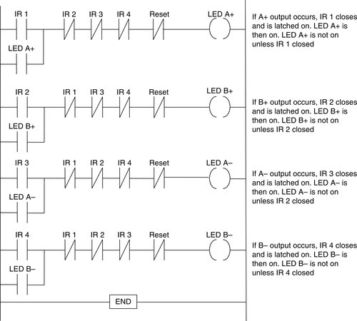
5. A+ and B+, C+, A– and B–, C–.
6. A+, B+, A−, B−, A+, A−.
7. M100 and M101 activated. Ten pulses on X401 counted. Then output.
8. See Figure A.11.

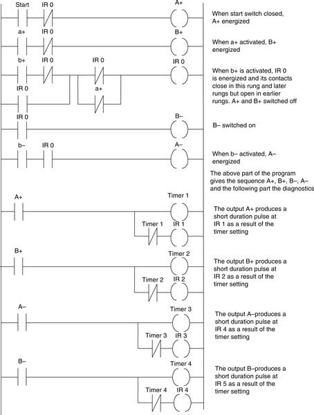
9. See Figure A.12.

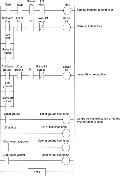
10. A basic specification might be as follows: The lift can only move when both access doors are closed and the lift door is closed. The lift will move from the ground floor to the first floor when a call command is given from the first floor and move to the ground floor when a call command is received from the ground floor. Signal lamps at each floor will indicate on each floor which floor the lift is at. See Figure A.13 for a possible program. You might like to refine the program by adding a timer which will sound an alarm if the lift takes too long between floors.