Data Handling
Abstract
This chapter is about PLC operations involving blocks of data representing a value, such blocks being termed words and stored in registers. Data handling involves such operations as moving numeric information from one location to another, comparing data values and carrying our simple arithmetic operations. Programs involving such operations are developed.
Timers, counters, and individual internal relays are all concerned with the handling of individual bits, that is, single on/off signals. Shift registers involve a number of bits with a group of internal relays being linked (see Chapter 11). The block of data in the register is manipulated. This chapter is about PLC operations involving blocks of data representing a value; such blocks are called words. A block of data is needed if we are to represent numbers rather than just a single on/off input. Data handling consists of operations involving moving or transferring numeric information stored in one memory word location to another word in a different location, comparing data values, and carrying out simple arithmetic operations. For example, there might be the need to compare a numeric value with a set value and initiate action if the actual value is less than the set value. This chapter is an introductory discussion of such operations.
12.1 Registers and Bits
A register is where data can be stored (see Section 8.1 for an initial discussion of registers). In a PLC there are a number of such registers. Each data register can store a binary word of usually 8 or 16 bits. The number of bits determines the size of the number that can be stored. The binary system uses only two symbols, 0 and 1 (see Chapter 3). Thus we might have the 4-bit number 1111. This is the denary number, that is, the familiar number system based on 10s, of 20 + 21 + 22 + 23 = 1 + 2 + 4 + 8 = 15. Thus a 4-bit register can store a positive number between 0 and 20 + 21 + 22 + 23 or 24 − 1 = 15. An 8-bit register can store a positive number between 0 and 20 + 21 + 22 + 23 + 24 + 25 + 26 + 27 or 28 − 1, that is, 255. A 16-bit register can store a positive number between 0 and 216 − 1, that is, 65,535.
Thus a 16-bit word can be used for positive numbers in the range 0 to 65,535. If negative numbers are required, the most significant bit is used to represent the sign, a 1 representing a negative number and a 0 a positive number; the format used for negative numbers is two's complement. Two's complement is a way of writing negative numbers so that when we add, say, the signed equivalent of +5 and –5, we obtain 0. Thus in this format, 1011 represents the negative number −5 and 0101 the positive number +5; 1011 + 0101 = (1)0000 with the (1) for the 4-bit number being lost. See Chapter 3 for further discussion.
The binary coded decimal (BCD) format is often used with PLCs when they are connected to devices such as digital displays. With the natural binary number there is no simple link between the separate symbols of a denary number and the equivalent binary number. You have to work out the arithmetic to decipher one number from the other. With the BCD system, each denary digit is represented, in turn, by a 4-bit binary number (four is the smallest number of binary bits that gives a denary number greater than 10, that is, 2n > 10). To illustrate this idea, consider the denary number 123. The 3 is represented by the 4-bit binary number 0011, the 2 by the 4-bit number 0010, and the 1 by 0001. Thus the BCD number of 123 is 0001 0010 0011. BCD is a convenient system for use with external devices that are arranged in denary format, such as decade switches (thumbwheel switches) and digital displays. Then four binary bits can be used for each denary digit. PLCs therefore often have inputs or outputs that can be programmed to convert BCD from external input devices to the binary format needed inside the PLC and from the binary format used internally in the PLC to BCD for external output devices (see Section 12.3).
The thumbwheel switch is widely used as a means of inputting BCD data manually into a PLC. It has four contacts that can be opened or closed to give the four binary bits to represent a denary number (Figure 12.1). The contacts are opened or closed by rotating a wheel using one's thumb. By using a number of such switches, data can be input in BCD format.

12.2 Data Handling
The following are examples of data-handling instructions to be found with PLCs.
12.2.1 Data Movement
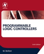
For moving data from one location or register to another, Figure 12.2 illustrates a common practice of using one rung of a ladder program for each move operation, showing the form used by three manufacturers: Mitsubishi, Allen-Bradley, and Siemens. For the rung shown,when there is an input to | | in the rung, the move occurs from the designated source address to the designated destination address. For data handling with these PLCs, the typical ladder program data-handling instruction contains the data-handling instruction, the source (S) address from where the data is to be obtained, and the destination (D) address to where it is to be moved. The approach that is used by some manufacturers, such as Siemens, is to regard data movement as two separate instructions, loading data from the source into an accumulator and then transferring the data from the accumulator to the destination. Figure 12.2c shows the Siemens symbol for the MOVE function. The data is moved from the IN input to the OUT output when EN is enabled.
Data transfers might be to move a preset value to a timer or counter, or a time or counter value to some register for storage, or data from an input to a register or a register to output. Figure 12.3 shows the rung, in the Allen-Bradley format, that might be used to transfer a number held at address N7:0 to the preset of timer T4:6 when the input conditions for that rung are met. A data transfer from the accumulated value in a counter to a register would have a source address of the form C5:18.ACC and a destination address of the form N7:0. A data transfer from an input to a register might have a source address of the form I:012 and a destination address of the form N7:0. A data transfer from a register to an output might have a source address of the form N7:0 and a destination address of the form O:030.

12.2.2 Data Comparison
The data comparison instruction gets the PLC to compare two data values. Thus it might be to compare a digital value read from some input device with a second value contained in a register. For example, we might want some action to be initiated when the input from a temperature sensor gives a digital value that is less than a set value stored in a data register in the PLC. PLCs generally can make comparisons for less than (< or LT or LES), equal to (= or = = or EQ or EQU), less than or equal to (≤ or .<= or LE or LEQ), greater than (> or GT or GRT), greater than or equal to (≥ or >= or GE or GEQ), and not equal to (≠ or <> or NE or NEQ). The parentheses alongside each of the terms indicates common abbreviations used in programming. As an illustration, in structured text we might have:
(*Check that boiler pressure P2 is less than pressure P1*)
Output := P2 < P1;
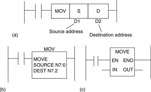
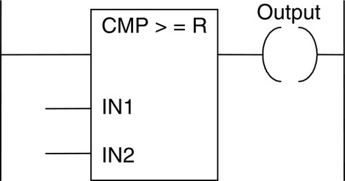
With ladder programs, for data comparison the typical instruction will contain the data-transfer instruction to compare data, the source (S) address from which the data is to be obtained for the comparison, and the destination (D) address of the data against which it is to be compared. The instructions commonly used for the comparison are the terms indicated in the preceding parentheses. Figure 12.4 shows the type of formats used by three manufacturers using the greater-than form of comparison. Similar forms apply to the other forms of comparison. In Figure 12.4a the format is that used by Mitsubishi, S indicating the source of the data value for the comparison and D the destination or value against which the comparison is to be made. Thus if the source value is greater than the destination value, the output is 1. In Figure 12.4b the Allen-Bradley format has been used. Here the source of the data being compared is given as the accumulated value in timer 4.0 and the data against which it is being compared is the number 400. Figure 12.4c shows the Siemens format. The values to be compared are at inputs IN1 and IN2 and the result of the comparison is at the output: 1 if the comparison is successful, otherwise 0. The R is used to indicate real numbers, that is, floating point numbers, I being used for integers, that is, fixed-point numbers involving 16 bits, and D for fixed-point numbers involving 32 bits. Both the inputs need to be of the same data type, such as REAL.
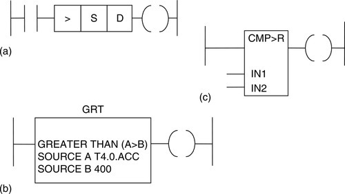
As an illustration of the use of such a comparison, consider the task of sounding an alarm if a sensor indicates that a temperature has risen above some value, say, 100°C. The alarm is to remain sounding until the temperature falls below 90°C. Figure 12.5 shows the ladder diagram that might be used. When the temperature rises to become equal to or greater than 100°C, the greater-than comparison element gives a 1 output and so sets an internal relay. There is then an output. This output latches the greater-than comparison element, so the output remains on, even when the temperature falls below 100°C. The output is not switched off until the less-than 90°C element gives an output and resets the internal relay.
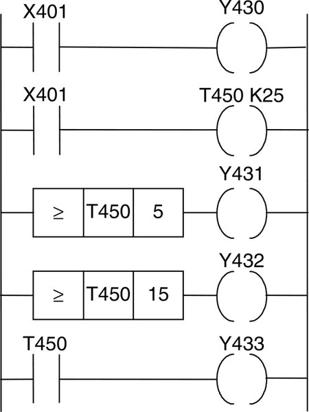
Another example of the use of comparison is when, say, four outputs need to be started in sequence, that is, output 1 starts when the initial switch is closed, followed sometime later by output 2, sometime later by output 3, and sometime later by output 4. Though this could be done using three timers, another possibility is to use one timer with greater-than or equal elements. Figure 12.6 shows a possible ladder diagram. When the X401 contacts close, the output Y430 starts. The timer is also started. When the timer-accumulated value reaches 5 s, the greater-than or equal-to element switches on Y431. When the timer-accumulated value reaches 15 s, the greater-than or equal-to element switches on Y432. When the timer reaches 25 s, its contacts switch on Y433.
12.2.3 Data Selection
There are a number of selection function blocks available with PLCs. Figure 12.7 shows the standard IEC symbols.

12.3 Arithmetic Functions
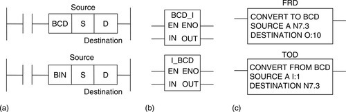
Most PLCs provide BCD-to-binary or integer and integer or binary-to-BCD conversions for use when the input might be a thumbwheel switch or the output to a decimal display. Figure 12.8a shows one form of instructions for use in such situations, Figure 12.8b the form used by Siemens for conversion of BCD to integer and integer to BCD, and Figure 12.8c the form used by Allen-Bradley.
12.3.1 Arithmetic Operations
Some PLCs are equipped to carry out just the arithmetic operations of addition and subtraction, others the four basic arithmetic operations of addition, subtraction, multiplication, and division, and still others can carry out these and various other functions such as the exponential. Addition and subtraction operations are used to alter the value of data held in data registers. For example, this might be to adjust a sensor input reading or perhaps obtain a value by subtracting two sensor values or alter the preset values used by timers and counters. Multiplication might be used to multiply some input before perhaps adding to or subtracting it from another.
The way PLCs have to be programmed to carry out such operations varies. In its PLCs, Allen-Bradley has such arithmetic operations as add (ADD), subtract (SUB), divide (DIV), multiply (MUL), and square root (SQR). Figure 12.9a shows the format for ADD; the other arithmetic functions have a similar format. The data in source A, which is at N7.1, is added to that in source B, which is at N7.3, and the result is put at the destination N7.5.
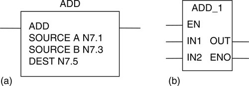
Figure 12.9b shows the basic form of the Siemens instructions for arithmetic functions. With integers the functions available are ADD_1 for addition, SUB_1 for subtraction, MUL_1 for multiplication, and DIV_1 for division, with the quotient as the result. The arithmetic functions are executed if there is a 1 at the enable EN input.
12.4 Closed Loop Control
You can control the temperature of a room by switching on an electric fire. The fire will heat the room up to the maximum temperature that is possible, bearing in mind the rate at which the fire heats the room and the rate at which it loses heat. This is termed open loop control in that there is no feedback to the fire to modify the rate at which it is heating the room. To control the temperature with feedback, you need a thermostat that can be set to switch the fire on when the room temperature is below the required value and switch it off when it goes above it. There is feedback of temperature information in this system; as such it is termed closed loop control.
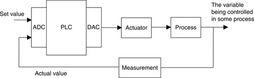
Closed loop control of some variable, such as the control of the temperature in a room, is achieved by comparing the actual value for the variable with the desired set value and then giving an output, such as switching on a heater, to reduce the difference. Figure 12.10 illustrates this idea by means of a block diagram. The actual value of the variable is compared with the set value and a signal is obtained representing the difference or error. A controller then takes this difference signal and gives an output to an actuator to give a response to correct the discrepancy.
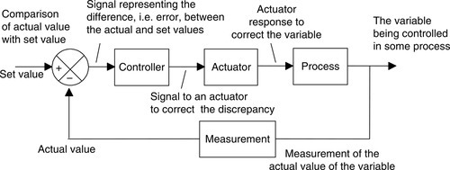
Figure 12.11 shows the arrangement that might be used with a PLC used to exercise the closed loop control. It has been assumed that the actuator and the measured values are analog and thus require conversion to digital; analog-to-digital and digital-to-analog units have thus been shown.
12.4.1 Modes of Control
There are a number of methods by which the controller can react to an error signal:
• On-off mode, in which the controller is essentially just a switch that supplies an on/off output signal depending on whether there is an error or not (Figure 12.12a). When there is an error, there is a constant output from the controller, regardless of the size of the error. A simple example of such a controller is the bimetallic thermostat (refer back to Figure 2.11) used with the central heating systems of many houses. This is just a form of switch that is off when the temperature is above the required temperature and on when it is below it. Because the control action is discontinuous and there are time lags in the system, oscillations of the controlled variable occur about the set value. For example, when a bimetallic thermostat switch switches on, there is a time delay before the heater begins to have an effect on the temperature, and when the temperature rises to the required temperature, there will be a time delay before the switched-off heater stops heating the system. However, on/off control is not too bad if the system has a large capacitance or inertia, so the effect of changes results in only slow changes in the variable. A dead band or hysteresis is often added to stop the controller from reacting to small error values and consequently constantly switching on and off when the variable is hovering about the set value. The switch-on value of the variable is thus different from the switch-off value (Figure 12.12b).
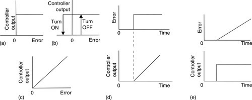
• Proportional mode, in which the controller gives an output to the actuator that is proportional to the difference between the actual value and the set value of the variable, that is, the error (Figure 12.12c). Such a form of control can be given by a PLC with basic arithmetic facilities. The set value and the actual values are likely to be analog and so are converted to digital, and then the actual value is subtracted from the set value and the difference multiplied by some constant, the proportional constant KP, to give the output, which, after conversion to analog, is the correction signal applied to the actuator:
• Integral mode, in which the controller output is proportional to the integral of the error with time, that is, the area under the error-time graph (Figure 12.12d).
• Derivative mode, in which the controller output is proportional to the rate at which the error is changing, that is, the slope of the error-time graph (Figure 12.12e):
• Combinations of modes, generally proportional plus integral plus derivative, which is referred to as PID mode.
Proportional control has a disadvantage in that, because of time lags inherent in the system, the correcting signal applied to the actuator tends to cause the variable to oscillate about the set value. What is needed is a correcting signal that is reduced as the variable gets close to the set value. This is obtained by PID control, the controller giving a correction signal that is computed from a proportional element (the P term), an element that is related to previous values of the variable (the integral I term), and an element related to the rate at which the variable is changing (the derivative D term).
The term tuning is used for determining the optimum values of KP, KI, and KD to be used for a particular control system. The value of KD/KP is called the derivative action time TD, and the value of KP/KI is called the integral action time TI; it is these terms KP, TD, and TI that are generally specified.
12.4.2 Control with a PLC
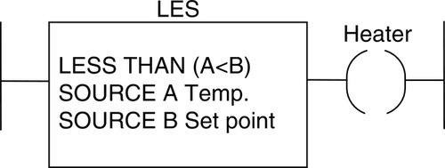
Figure 12.13 shows a PLC ladder rung that can be used to exercise two-step control. The output is turned on when source A, the actual temperature, is less than source B, the required temperature, that is, the set value.
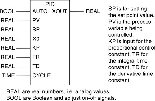
Many PLCs provide the PID calculation to determine the controller output as a standard function block. All that is then necessary is to pass the desired parameters, that is, the values of KP, KI, and KD, and input/output locations to the routine via the PLC program. Figure 12.14 shows the IEC 61131-3 standard symbol for the PID control function. When AUTO is set, the function blocks calculate the output value XOUT needed to bring the variable closer to the required set value.
Summary
Data handling consists of operations involving moving or transferring numeric information stored in one memory word location to another word in a different location, comparing data values, and carrying out simple arithmetic operations.
Closed loop control of some variable is achieved by comparing the actual value for the variable with the desired set value and then giving an output to reduce the difference. With proportional control, the controller gives the actuator an output that is proportional to the difference between the actual value and the set value of the variable, that is, the error. With PID control, the controller gives a correction signal that is computed from a proportional element, the P term, the integral term I, is an element giving a signal related to previous values of the variable and is the area under the error-time graph, and an element giving a signal related to the rate at which the variable is changing (the derivative D term).
Problems
Problems 1 through 9 have four answer options: A, B, C, or D. Choose the correct answer from the answer options. Problems 1 and 2 refer to Figure 12.15, which shows two formats used for the move operation.
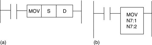
1. Decide whether each of these statements is true (T) or false (F). In Figure 12.15a, the program instruction is to:
(i) Move the value in S to D, leaving S empty.
(ii) Copy the value in S and put it in D.
A. (i) T (ii) T
B. (i) T (ii) F
C. (i) F (ii) T
D. (i) F (ii) F
2. Decide whether each of these statements is true (T) or false (F). In Figure 12.15b, the program instruction is to:
(i) Move the value in N7:1 to N7:2, leaving N7:1 empty.
(ii) Copy the value in N7:1 and put it in N7:2.
A. (i) T (ii) T
B. (i) T (ii) F
C. (i) F (ii) T
D. (i) F (ii) F
Problems 3 and 4 refer to Figure 12.16, which shows two versions of a ladder rung involving a comparison.
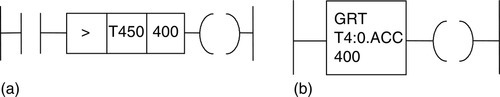
3. Decide whether each of these statements is true (T) or false (F). In Figure 12.16a, the program instruction is to give an output:
(i) When the accumulated time in timer T450 exceeds a value of 400.
(ii) Until the accumulated time in timer T450 reaches a value of 400.
A. (i) T (ii) T
B. (i) T (ii) F
C. (i) F (ii) T
D. (i) F (ii) F
4. Decide whether each of these statements is true (T) or false (F). In Figure 12.16b, the program instruction is to give an output:
(i) When the accumulated time in timer T4:0 exceeds a value of 400.
(ii) Until the accumulated time in timer T4:0 reaches a value of 400.
A. (i) T (ii) T
B. (i) T (ii) F
C. (i) F (ii) T
D. (i) F (ii) F
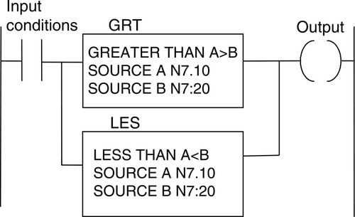
5. Decide whether each of these statements is true (T) or false (F). In Figure 12.17, when the input conditions are met, the program instruction is to give an output when the data:

(i) In N7:10 equals that in N7:20.
(ii) In N7:10 is less than that in N7:20.
A. (i) T (ii) T
B. (i) T (ii) F
C. (i) F (ii) T
D. (i) F (ii) F
6. Decide whether each of these statements is true (T) or false (F). In Figure 12.18, the program instruction is to give, when the input conditions are met, an output when:
(i) The data in N7:10 is not equal to that in N7:20.
(ii) The data in N7:10 is greater or less than that in N7:20.
A. (i) T (ii) T
B. (i) T (ii) F
C. (i) F (ii) T
D. (i) F (ii) F
7. In Figure 12.19, when the input conditions are met the program instruction is to give:
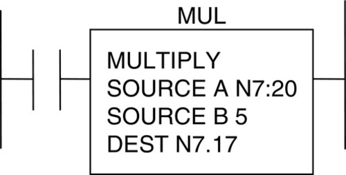
A. The sum of the data at sources A and B
B. The product of the data in sources A and B
C. The difference between the data in sources A and B
D. The value given by dividing the data in source A by that in B
8. Decide whether each of these statements is true (T) or false (F). For the Siemens function box shown in Figure 12.20, the output will be set when:
(i) Inputs IN1 and IN2 are both the same REAL number.
(ii) Input IN1 is a REAL number greater than input IN2.
A. (i) T (ii) T
B. (i) T (ii) F
C. (i) F (ii) T
D. (i) F (ii) F
9. Decide whether each of these statements is true (T) or false (F). For the Siemens function box shown in Figure 12.21, the output will be set when:

(i) Inputs IN1 and IN2 are both the same REAL number.
(ii) Input IN1 is a REAL number greater than input IN2.
A. (i) T (ii) T
B. (i) T (ii) F
C. (i) F (ii) T
D. (i) F (ii) F
10. Devise ladder programs for systems that will carry out the following tasks:
(a) Switch on a pump when the water level in a tank rises to above 1.2 m and switch it off when it falls below 1.0 m.
(b) Switch on a pump; then 100 s later, switch on a heater; then a further 30 s later, switch on the circulating motor.
(c) Switch on a heater when the temperature is less than the set temperature.
(d) Turn on a lamp when a data source is not giving 100.
11. Describe the operation of an on/off controller and explain how it might be used to control the temperature in a domestic central heating system.
12. Explain the principle of a proportional controller.
Lookup Tasks
13. For a particular PLC model, determine what data-handling functions it has.