
Programs
This chapter extends the examples given in previous chapters to show programs developed to complete specific tasks. These include tasks that involve temperature control and a number involving pneumatic valves.
14.1 Temperature Control
Consider the task of using a PLC as an on/off controller for a heater in the control of temperature in some enclosure. The heater is to be switched on when the temperature falls below the required temperature and switched off when the temperature is at or above the required temperature. The basic algorithm might be considered to be:
IF temperature below set value
THEN
 DO switch on heater
ELSE
 DO switch off heater
ENDIF
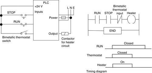
What is required to give the input to a PLC is a sensor-signal conditioner arrangement that will give no input when the temperature is below the required temperature and an input when it is above. One such device is the bimetallic thermostat (Figure 14.1; see Section 2.1.5). A bimetallic strip consists of two different metals strips of the same length bonded together. Because the metals have different coefficients of expansion, when the temperature increases the composite strip bends into a curve with the higher coefficient metal on the outside of the curve. The movement may be used to open or close electrical contacts and so operate as a temperature-dependent switch. If the actual temperature is above the required temperature, the bimetallic strip is in an off position and there is no circuit voltage output. If the actual temperature is below the required temperature, the bimetallic strip moves into the on position and the voltage is switched on, so there is an output. The thermostat output is thus just off or on and the input to the PLC is no voltage or a voltage. Figure 14.2 shows the PLC connections and a ladder program that can be used.

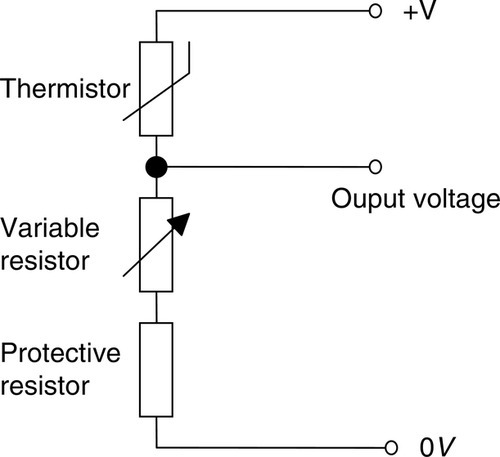
An alternative to the bimetallic thermostat is to use a thermocouple, a thermistor, or an integrated chip (see Section 2.1.5) as a temperature sensor. When connected in an appropriate circuit, the sensor will give a suitable voltage signal related to the temperature. For example, with a thermistor, its resistance changes when the temperature changes, and this can be converted into a voltage signal by using a potential divider circuit. Figure 14.3 shows a possible solution involving a potential divider circuit to convert the resistance change into a voltage change. Suppose we use a 4.7 kΩ bead thermistor. This has a resistance of 4.7 kΩ at 25°C, 15.28 kΩ at 0°C, and 0.33 kΩ at 100°C. The variable resistor might be 0 to 10 kΩ. It enables the sensitivity of the arrangement to be altered. However, if the variable resistor was set to zero resistance, without a protective resistor, we could possibly have a large current passed through the thermistor. The maximum power that the thermistor can withstand is specified as 250 mW. Thus, with a 6 V supply, the variable resistor set to zero resistance, the protective resistance of R, and the thermistor at 100°C, the current I through the thermistor is given by V = IR as 6 = I(0 + R + 330), and so I = 6/(R + 330). The power dissipated by the thermistor is I2 × 330, so if we want this to be significantly below the maximum possible—say, 100 mW—then we have 0.100 = I2 × 330, and so R needs to be about 15 Ω.
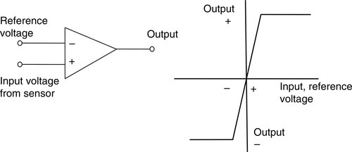
This voltage output from the thermistor can be compared, using an operational amplifier, with the voltage set for the required temperature so that a high-output signal is given when the temperature is above the required temperature and a low-output signal when it is below, or vice versa. Operational amplifiers are widely used to give on/off signals based on the relative value of two input signals—a set-point voltage and a sensor voltage (see Section 4.2.2). One signal is connected to the noninverting terminal and the other to the inverting terminal. The operational amplifier determines whether the signal to the inverting terminal is above or below that of the noninverting terminal. Figure 14.4 shows the output/input relationship for the operational amplifier. By reversing the reference and input voltage connections, the output polarity is changed.
Thus we can arrange that when the temperature falls from above the required temperature to below it, the output signal switches from a high to a low value. The PLC can then be programmed to give an output when there is a low input, and this output can be used to switch on the heater and switch off the heater when the input goes high.
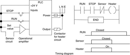
Figure 14.5 shows the arrangement that might be used and the basic elements of a ladder program. The input from the operational amplifier has been connected to the input port. This input has contacts that are normally closed. When the input goes high, the contacts open. The output to the heater is taken from the output port. Thus there is an output when the input from the sensor is low and no output when the input is high.
Consider a more complex temperature control task involving a domestic central heating system (Figure 14.6). The central heating boiler is to be thermostatically controlled and will supply hot water to the radiator system in the house as well as to the hot water tank to provide hot water from the taps in the house. Pump motors have to be switched on to direct the hot water from the boiler to either or both the radiator and hot water systems, according to whether the temperature sensors for the room temperature and the hot water tank indicate that the radiators or tank need heating. The entire system is to be controlled by a clock so that it operates for only certain hours of the day. Figure 14.7 shows how this might be programmed.
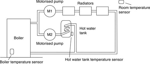
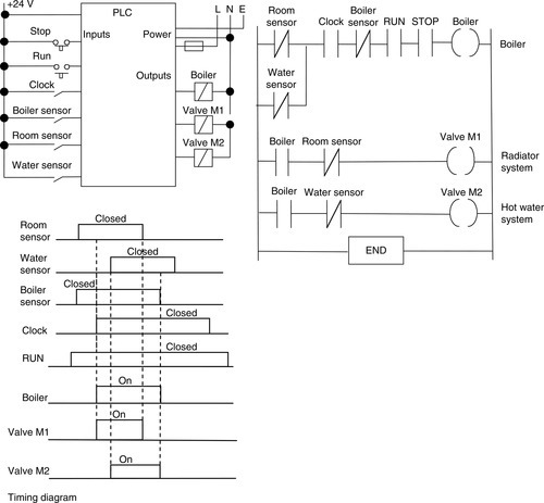
The inputs might be from sensors feeding through operational amplifiers so that a high output is given when the sensor temperature is above the set value and so there is a need to switch things off when the output from the operational amplifier drops to a low output. When the system is running, the boiler is switched on if the clock and either the water sensor or the room sensor inputs are switched off. The motorized valve M1 is switched on if the boiler is on and if the room temperature sensor is switched off. The motorized valve M2 is switched on if the boiler is on and if the water temperature sensor is switched off.
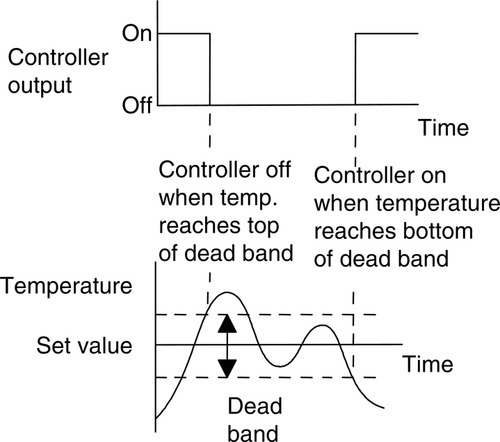
There is a problem with a simple on/off system in that when the room temperature is hovering about the set value, the sensor might be reacting to very slight changes in temperature and almost continually switching on or off. Thus when it is at its set value, a slight draft might cause it to operate. This problem can be reduced if the heater is switched on at a lower temperature than the one at which it is switched off (Figure 14.8). The term dead band is used for the values between the on and off values. For example, if the set value on a thermostat is 20°C, a dead band might mean that it switches on when the temperature falls to 19.5° and off when it is 20.5°. The temperature has thus to change by one degree for the controller to switch the heater on or off, and thus smaller changes do not cause the thermostat to switch. A large dead band results in large fluctuations of temperature about the set temperature; a small dead band will result in an increased frequency of switching. The bimetallic thermostat shown in Figure 14.1 has a permanent magnet on one switch contact and a small piece of soft iron on the other; this has the effect of producing a small dead band in that, when the switch is closed, a significant rise in temperature is needed for the bimetallic element to produce sufficient force to separate the contacts.
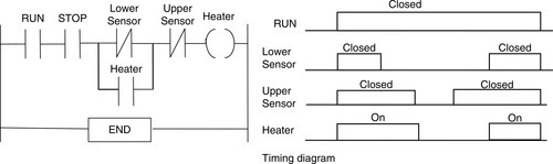
An alternative to this type of arrangement is to use two inputs to the PLC, one with a set temperature at the top of the required dead band and the other at the bottom of the dead band. Thus the program in Figure 14.5 can be amended to become as shown in Figure 14.9. Initially, when the program is started, the heater is switched on. When the lower set temperature is reached, the lower sensor switches off. Because of the latching, the heater remains on. When the upper set temperature is reached, the upper sensor switches off, and consequently the heater is switched off. When the temperature drops, it has to drop to the lower set temperature before the heater is switched on again.
In the previous discussion a simple on/off form of temperature control has been used, with perhaps a comparator op-amp giving a 1 output when the temperature is above the set temperature and 0 when it is below. The output to the heating system is then just on or off. A more elaborate system is to use proportional control with the output to the heating system being a signal proportional to the difference in temperature between that occurring and the set value. The program might then carry out the following tasks:
1. Read the actual temperature input after conversion from analog to digital by an ADC.
2. Input the set point temperature.
3. Subtract the actual temperature from the set point temperature.
4. Multiply the result by the proportional constant.
5. Use the result to control the value of the output to the heater.
14.2 Valve Sequencing
Consider tasks involving directional control valves (see Section 2.2.2 for an introductory discussion).
14.2.1 Cyclic Movement
Consider the task of obtaining cyclic movement of a piston in a cylinder. This might be to periodically push workpieces into position in a machine tool with another similar but out-of-phase arrangement used to remove completed workpieces. Figure 14.10 shows the valve and piston arrangement that might be used, a possible ladder program, and a chart indicating the timing of each output.
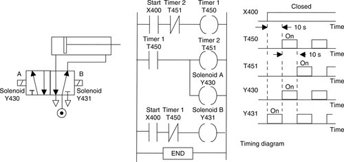
Consider both timers set for 10 s. When the start contacts X400 are closed, timer T450 starts. There is also an output from Y431. Output Y431 is one of the solenoids used to actuate the valve. When it is energized it causes pressure supply P to be applied to the right-hand end of the cylinder and the left-hand side to be connected to the vent to the atmosphere. The piston thus moves to the left. After 10 s, the normally open T450 contacts close and the normally closed T450 contacts open. This stops output Y431, starts timer T451, and energizes output Y430. As a result, pressure supply P is applied to the left-hand side of the piston and the right-hand side is connected to the vent to the atmosphere. The piston now moves to the right. After 10 s, the normally closed T451 contacts are opened. This causes the normally closed T450 contacts to close, and so Y431 is energized. Thus the sequence repeats itself.
14.2.2 Sequencing
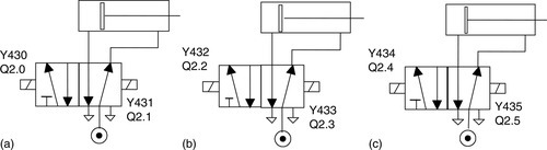
Consider another task involving three pistons A, B, and C that have to be actuated in this sequence: A to the right, A to the left, B to the right, B to the left, C to the right, C to the left. (Such a sequence is often written A+, A−, B+, B−, C+, C−.) Figure 14.11 illustrates the valves that might be used; Figures 14.12 and 14.13 show ladder programs involving timers that might be used. An alternative would involve the use of a shift register.
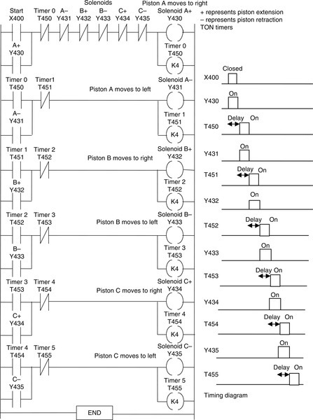
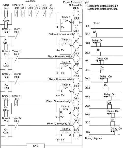
X400/I0.0 is the start switch. When it is closed there is an output from Y430/Q2.0, and timer T450/T0 starts. The start switch is latched by the output. Piston A moves to the right. After the set time, K = 4, the normally closed timer T450/internal relay F0.0 contacts open and the normally open timer T450/internal relay F0.0 contacts close. This switches off Y430/Q2.0, energizes Y431/Q2.1, and starts timer T451/T1. Piston A moves left. In rung 2, the T450/internal relay F0.0 contacts are latched and so the output remains on until the set time has been reached. When this occurs, the normally closed timer T451/internal relay F0.1 contacts open and the normally open T451/internal relay F0.1 contacts close. This switches off Y431/Q2.1, energizes Y432/Q2.2, and starts timer T452/T2. Piston B moves right. Each succeeding rung activates the next solenoid. Thus, in sequence, each of the outputs is energized.
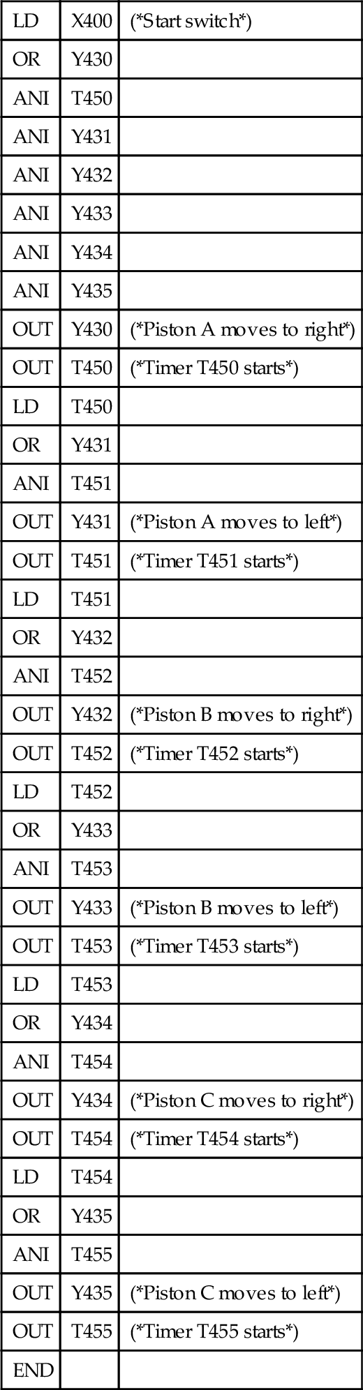
The program instruction list, in the Mitsubishi format, for the preceding program is as follows:
| LD | X400 | (*Start switch*) |
| OR | Y430 | |
| ANI | T450 | |
| ANI | Y431 | |
| ANI | Y432 | |
| ANI | Y433 | |
| ANI | Y434 | |
| ANI | Y435 | |
| OUT | Y430 | (*Piston A moves to right*) |
| OUT | T450 | (*Timer T450 starts*) |
| LD | T450 | |
| OR | Y431 | |
| ANI | T451 | |
| OUT | Y431 | (*Piston A moves to left*) |
| OUT | T451 | (*Timer T451 starts*) |
| LD | T451 | |
| OR | Y432 | |
| ANI | T452 | |
| OUT | Y432 | (*Piston B moves to right*) |
| OUT | T452 | (*Timer T452 starts*) |
| LD | T452 | |
| OR | Y433 | |
| ANI | T453 | |
| OUT | Y433 | (*Piston B moves to left*) |
| OUT | T453 | (*Timer T453 starts*) |
| LD | T453 | |
| OR | Y434 | |
| ANI | T454 | |
| OUT | Y434 | (*Piston C moves to right*) |
| OUT | T454 | (*Timer T454 starts*) |
| LD | T454 | |
| OR | Y435 | |
| ANI | T455 | |
| OUT | Y435 | (*Piston C moves to left*) |
| OUT | T455 | (*Timer T455 starts*) |
| END |
14.2.3 Sequencing Using a Sequential Function Chart
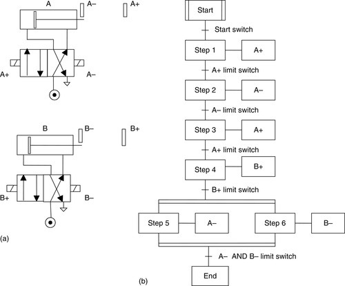
As an illustration of the use of a sequential function chart to describe a program involving sequential control of pneumatic valves and cylinders, consider the situation in which we have two cylinders with the required piston sequence A+. A−, A+, B+ and then simultaneously A− and B−, that is, piston A moves out to full stroke, then it retracts, then it is switched on again to full stroke, then B is switched on to full stroke, and then simultaneously both A and B retract (Figure 14.14a). The sequential function chart for the program is shown in Figure 14.14b.
14.2.4 Car Park Barrier Operation Using Valves
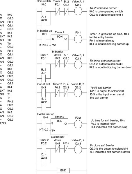
Consider the use of pneumatic valves to operate car park barriers. The in-barrier is to be opened when the correct money is inserted in the collection box; the out-barrier is to open when a car is detected at that barrier. Figure 14.15 shows the type of system that might be used. The valves used to operate the barriers have a solenoid to obtain one position and a return spring to give the second position. Thus when the solenoid is not energized, the position given is that obtained by the spring. The valves are used to cause the pistons to move. When the pistons move upward, the movement causes the barrier to rotate about its pivot and so lift. When a piston retracts, under the action of the return spring, the barrier is lowered. When a barrier is down, it trips a switch; when it's up, it trips a switch. These switches are used to give inputs indicating when the barrier is down or up. Sensors are used to indicate when the correct money has been inserted in the collection box for a vehicle to enter and to sense when a vehicle has approached the exit barrier.
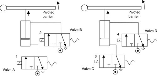
Figure 14.16 shows the form a ladder program could take: (a) the Mitsubishi program and (b) the Siemens program. The output Y430/Q2.0 to solenoid 1 to raise the entrance barrier is given when the output from the coin box sensor gives the X400/I0.0 input. The Y430/Q2.0 is latched and remains on until the internal relay M100/F0.1 opens. The output will also not occur if the barrier is in the process of being lowered and there is the output Y431/Q2.1 to solenoid 2. The timer T450/T1 is used to hold the barrier up for 10 s, being started by input X402/I0.2 from a sensor indicating the barrier is up. At the end of that time, output Y431/Q2.1 is switched on, activates solenoid 2, and lowers the barrier. The exit barrier is raised by output Y432/Q2.2 to solenoid 3 when a sensor detects a car and gives input X401/I0.1. When the barrier is up, timer T451/T2 is used to hold the barrier up for 10 s, being started by input X404/I0.4 from a sensor indicating the barrier is up. At the end of the time, output Y433/Q2.3 is switched on, activating solenoid 4 and lowering the barrier.
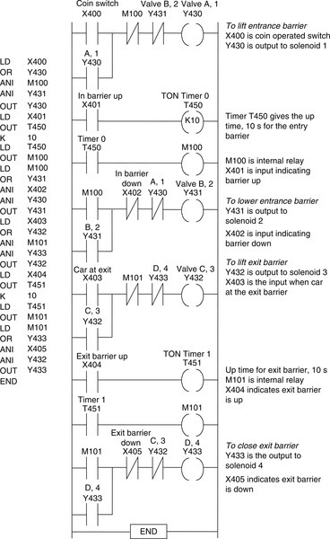
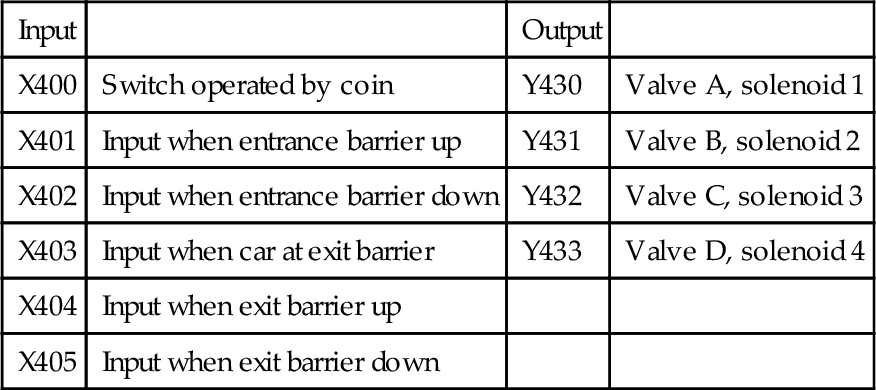
The inputs and outputs for the Mitsubishi program are as follows:
| Input | Output | ||
| X400 | Switch operated by coin | Y430 | Valve A, solenoid 1 |
| X401 | Input when entrance barrier up | Y431 | Valve B, solenoid 2 |
| X402 | Input when entrance barrier down | Y432 | Valve C, solenoid 3 |
| X403 | Input when car at exit barrier | Y433 | Valve D, solenoid 4 |
| X404 | Input when exit barrier up | ||
| X405 | Input when exit barrier down |
For the Siemens program:
| Input | Output | ||
| I0.0 | Switch operated by coin | Q2.0 | Valve A, solenoid 1 |
| I0.1 | Input when entrance barrier up | Q2.1 | Valve B, solenoid 2 |
| I0.2 | Input when entrance barrier down | Q2.2 | Valve C, solenoid 3 |
| I0.3 | Input when car at exit barrier | Q2.3 | Valve D, solenoid 4 |
| I0.4 | Input when exit barrier up | ||
| I0.5 | Input when exit barrier down |

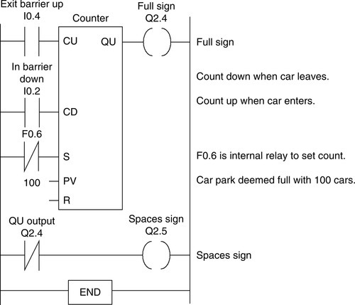
We could add to this program a system to keep check of the number of vehicles in the car park, illuminating a sign to indicate “Spaces” when the car park is not full and a sign “Full” when there are no more spaces. This could be achieved using an up- and down-counter. Figure 14.17 shows a possible Siemens ladder program.
14.2.5 Controlled Reset of Cylinders
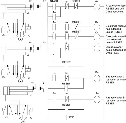
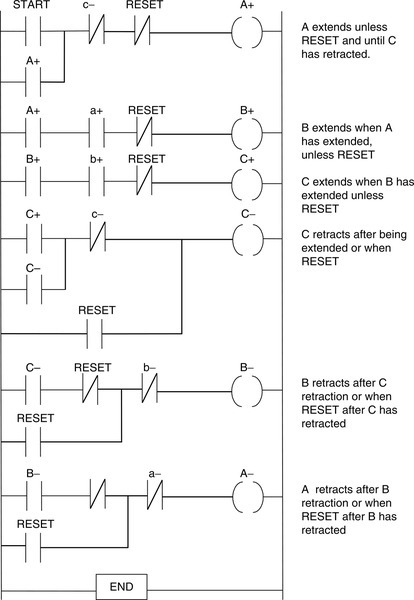
During the operation of a system involving a number of cylinders, it is possible that a system component may fail and leave cylinders in unsafe positions. The program might thus be modified so that a reset input can move all the cylinders back to their original positions. For example, with three cylinders A, B, and C and the requirement to give the sequence A+ B+ C+ C− B− A−, we can incorporate a RESET input that will return all the cylinders to their unextended positions, that is, A−, B− and C−. Figure 14.18 shows such a program.
When a fault occurs, a possibly safer closing-down operation is to close the cylinders down in a particular sequence. Figure 14.19 shows a possible program for closing down the cylinders in the sequence C− B− A−.
14.3 Conveyor Belt Control
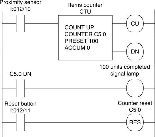
Consider a program that is used to count the number of items put onto a conveyor belt from work cells and give an alert when the number reaches 100. This program might be part of a bigger program used to control a production unit. A proximity sensor can be used to sense when an item is put on the conveyor so that a 1 signal is produced each time. The program might thus be as shown in Figure 14.20, which uses the Allen-Bradley format.
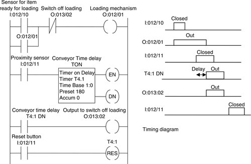
A further possibility in this conveyor belt problem is that too many items must not be put on the belt at any one time. A program that might achieve this goal involves instituting a time delay after an item is put on the belt and before the next item can be loaded onto the belt. Figure 14.21 shows the program elements for that specification. When an item passes the proximity sensor, the on-delay timer is started, and only when that is completed can another item be loaded.
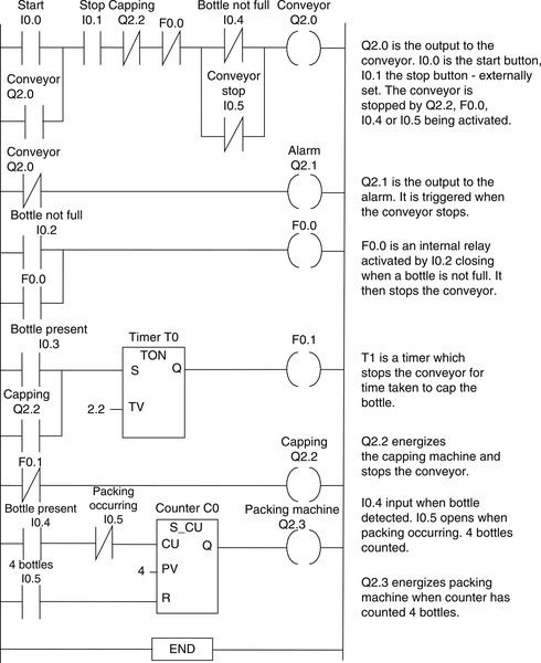
14.3.1 Bottle Packing
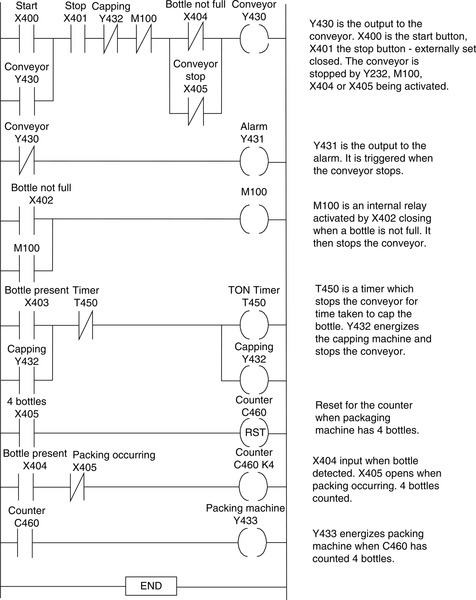
Consider a production-line problem involving a conveyor being used to transport bottles to a packaging unit, with the items being loaded onto the conveyor, checked to ensure they are full and capped, and then the correct number of bottles (four) being packed in a container. The required control actions are thus: If a bottle is not full, the conveyor is stopped; the capping machine is activated when a bottle is at the required position, the conveyor being stopped during this time; count four bottles and activate the packing machine, with the conveyor stopped if another bottle comes to the packing point at that time; and sound an alarm when the conveyor is stopped.
The detection of whether a bottle is full could be done with a photoelectric sensor that could then be used to activate a switch (X402/I0.2 input). The presence of a bottle for the capping machine could also be by means of a photoelectric sensor (X403/I0.3 input). The input to the counter to detect the four bottles could be also from a photoelectric sensor (X404/I0.4 input). The other inputs could be start (X400/I0.0 input) and stop (X401/I0.1 input) switches for the conveyor and a signal (X405/I0.5 input) from the packaging machine as to when it is operating and has received four bottles and so is not ready for any further caps. Figures 14.22 and 14.23 show a possible ladder program that could be used in Mitsubishi format and in Siemens format, respectively.
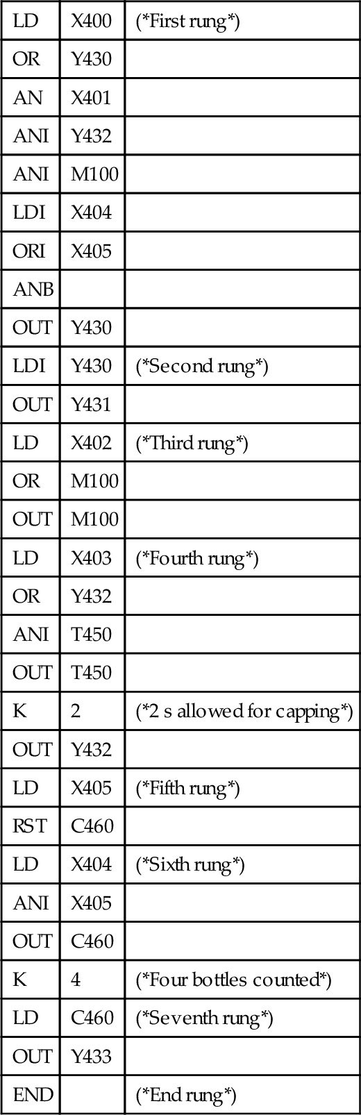
The Mitsubishi program in instruction list is as follows:
| LD | X400 | (*First rung*) |
| OR | Y430 | |
| AN | X401 | |
| ANI | Y432 | |
| ANI | M100 | |
| LDI | X404 | |
| ORI | X405 | |
| ANB | ||
| OUT | Y430 | |
| LDI | Y430 | (*Second rung*) |
| OUT | Y431 | |
| LD | X402 | (*Third rung*) |
| OR | M100 | |
| OUT | M100 | |
| LD | X403 | (*Fourth rung*) |
| OR | Y432 | |
| ANI | T450 | |
| OUT | T450 | |
| K | 2 | (*2 s allowed for capping*) |
| OUT | Y432 | |
| LD | X405 | (*Fifth rung*) |
| RST | C460 | |
| LD | X404 | (*Sixth rung*) |
| ANI | X405 | |
| OUT | C460 | |
| K | 4 | (*Four bottles counted*) |
| LD | C460 | (*Seventh rung*) |
| OUT | Y433 | |
| END | (*End rung*) |
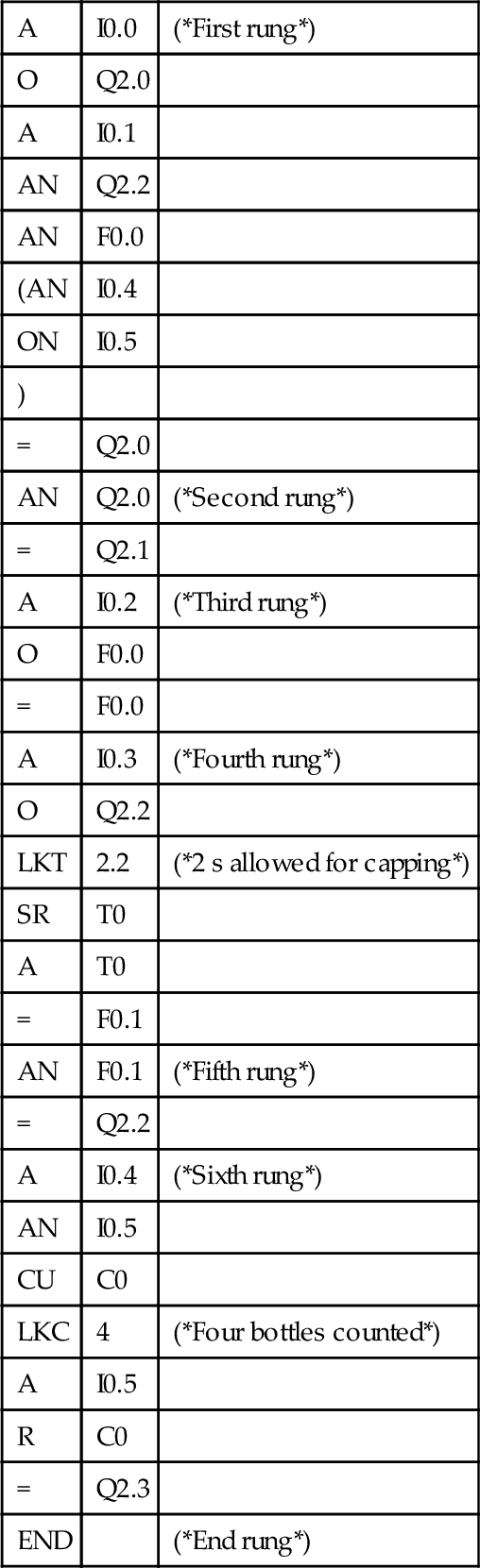
The Siemens program in instruction list is:
14.4 Control of a Process
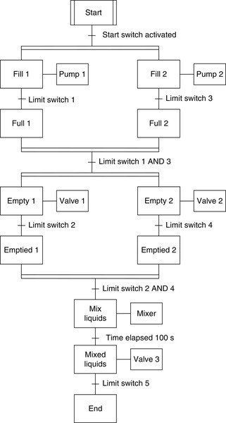
The following is an illustration of the use of a sequential flow chart for programming. The process (Figure 14.24a) involves two fluids filling two containers: When the containers are full, their contents are then emptied into a mixing chamber, from which the mixture is then discharged. The whole process is then repeated. Figure 14.24b shows the type of valve that might be used in such a process. It is solenoid operated to give flow through the valve, and then, when the solenoid is not activated, a spring returns the valve to the closed position.
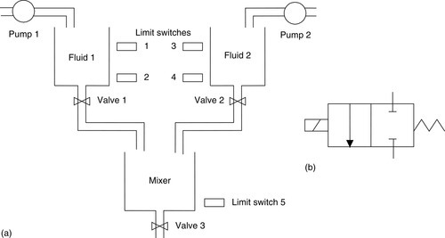
Figure 14.25 shows the sequential function chart program. When the start switch is activated, fill 1 and fill 2 occur simultaneously as a result of the actions of pumps 1 and 2 being switched on. When limit switch 1 is activated, fill 1 ceases; likewise, when limit switch 3 is activated, fill 2 ceases. We then have the containers for fluid 1 and fluid 2 full. The action that occurs when both limit switch 1 and 3 are activated is that the containers start to empty, the action being the opening of valves 1 and 2. When limit switches 2 and 4 are activated, the containers are empty. The next stage, the mixing of the liquids, is then determined when limit switch 2 and limit switch 4 are both activated. After a time of 100 s, the mixing ceases and the mixed liquids empty through valve 3. When limit switch 5 is activated, the program reaches the end of its cycle and the entire sequence is then repeated.
As a further illustration, consider a process to control liquid in a storage tank that can be emptied by a valve. Before power is supplied, the valve on the pipe supplying the tank has to be closed. On power being supplied, the tank might be already full or empty. If full it is to be emptied through the output valve. An empty tank is then to be filled by the input valve being opened. When full it is to be emptied. Figure 14.26 shows the sequential flow chart program for the process.

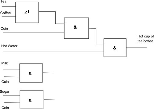
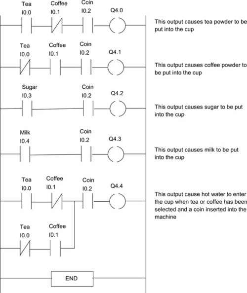
14.5 A Selection Example: A Drinks Machine
Consider a drinks machine that allows the selection of tea or coffee, milk or no milk, sugar or no sugar, and will supply the required hot drink on the insertion of a coin. Figure 14.27 shows the function block diagram. There is an output from the first OR gate of a signal when tea or coffee is selected. The first AND gate gives an output when there has been a selection of tea or coffee and a coin has been inserted into the machine Finally, the output from this gate goes to the final AND gate which gives an output which combines hot water with the tea. Milk and sugar are optional additions which can occur after a coin has been inserted. Figure 14.28 shows a ladder program for the drinks machine.
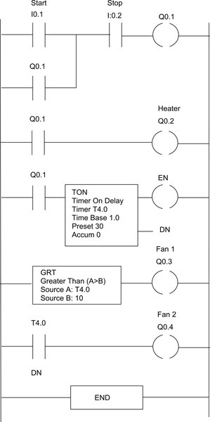
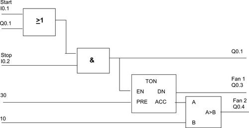
14.6 A Data Comparison Example: A Fan Heater
Consider a simple example of the use of the data greater-than comparison. An electric heater is to heat up when switched on, and then after 10 s a fan starts and then after 30 s another fan starts. Figure 14.29 shows a possible ladder program and Figure 14.30 a functional block diagram.
Problems
1. This problem is essentially part of the domestic washing-machine program. Devise a ladder program to switch on a pump for 100 s. It is then to be switched off and a heater switched on for 50 s. Then the heater is to be switched off and another pump is to be used to empty the water.
2. Devise a ladder program that can be used with a solenoid valve-controlled double-acting cylinder, that is, a cylinder with a piston that can be moved either way by means of solenoids for each of its two positions, and moves the piston to the right, holds it there for 2 s, and then returns it to the left.
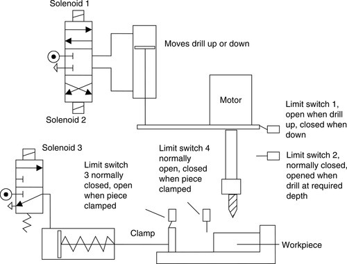
3. Devise a ladder program that could be used to operate the simplified task shown in Figure 14.31 for the automatic drilling of workpieces. The drill motor and the pump for the air pressure for the pneumatic valves must be started. The workpiece has to be clamped. The drill then must be lowered and drilling must be started to the required depth. Then the drill has to be retracted and the workpiece unclamped.
4. What are the principles to be observed in installing a safe emergency stop system with a PLC?
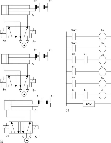
5. The inputs from the limit switches, the start switch, and the outputs to the solenoids of the valves shown in Figure 14.32a are connected to a PLC that has the ladder program shown in Figure 14.32b. What is the sequence of the cylinders?
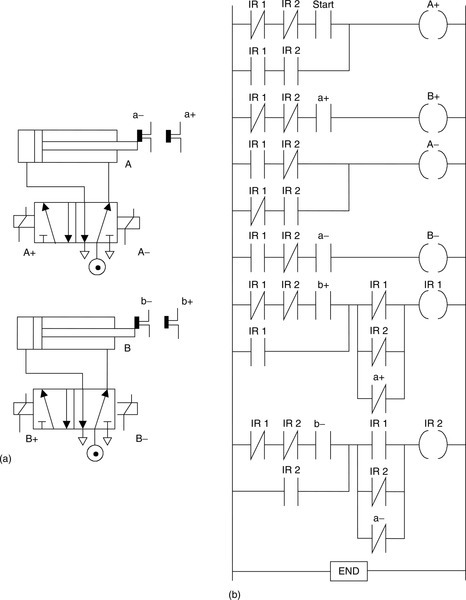
6. The inputs from the limit switches, the start switch, and the outputs to the solenoids of the valves shown in Figure 14.33a are connected to a PLC that has the ladder program shown in Figure 14.33b. What is the sequence of the cylinders?
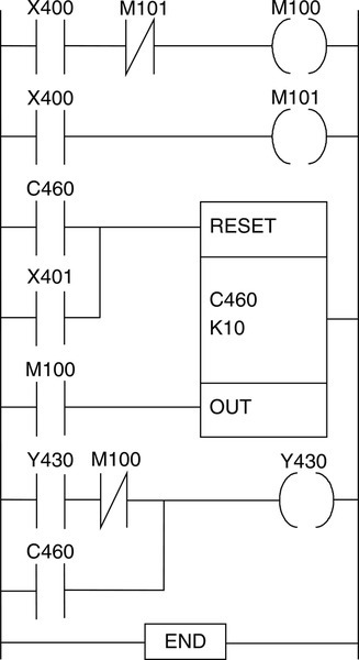
7. Figure 14.34 shows a ladder program involving a counter C460, inputs X400 and X401, internal relays M100 and M101, and an output Y430. X400 is the start switch. Explain how the output Y430 is switched on.
8. Write a ladder program that will switch on two motors when the start switch is operated, then switch off one motor after 200 s and the other motor after a further 100 s. When both motors have been switched off, a third motor is to be switched on for 50 s. The cycle is then to repeat itself unless a stop switch has been activated.
9. Write a ladder program to switch on a motor when the start switch is momentarily activated, with the motor remaining on for 50 s. At the end of that time a second motor is to be switched on for a further 50 s. A third motor is to be switched on 10 s before the second motor switches off and is to remain on for 50 s. The cycle is then to repeat itself unless a stop switch has been activated.
10. Suggest the control problem specification that might be required for a passenger lift that is to operate between the ground floor and the first floor of a building, and devise a ladder program to carry out the specification.
Lookup Tasks
11. Find a PLC that could be used for (a) the central heating system shown in Figure 14.7 and (b) the bottle-packing system shown in Figures 14.22 or 14.23.
12. Find suitable sensors for use in (a) the conveyor belt system described in Figure 14.20 and (b) the bottle-packing system described in Figure 14.23.