
Input/Output Devices
Abstract
This chapter is a brief consideration of typical input and output devices used with PLCs. The many devices considered include digital and analogue devices such as mechanical switches for position detection, proximity switches, photoelectric switches, encoders, temperature and pressure switches, potentiometers, linear variable differential transformers, strain gauges, thermistors, thermotransistors and thermocouples. Output devices considered include relays, contactors, solenoid valves and motors.
This chapter is a brief consideration of typical input and output devices used with PLCs. The input devices considered include digital and analog devices such as mechanical switches for position detection, proximity switches, photoelectric switches, encoders, temperature and pressure switches, potentiometers, linear variable differential transformers, strain gauges, thermistors, thermotransistors, and thermocouples. Output devices considered include relays, contactors, solenoid valves, and motors.
2.1 Input Devices
The term sensor is used for an input device that provides a usable output in response to a specified physical input. For example, a thermocouple is a sensor that converts a temperature difference into an electrical output. The term transducer is generally used to refer to a device that converts a signal from one form to a different physical form. Thus sensors are often transducers, but also other devices can be transducers, such as a motor that converts an electrical input into rotation.
Sensors that give digital or discrete, that is, on/off, outputs can be easily connected to the input ports of PLCs. An analog sensor gives an output proportional to the measured variable. Such analog signals have to be converted to digital signals before they can be input to PLC ports.
The following are some of the more common terms used to define the performance of sensors:
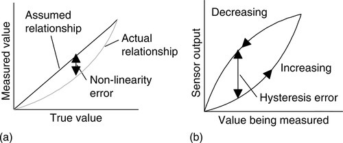
• Accuracy is the extent to which the value indicated by a measurement system or element might be wrong. For example, a temperature sensor might have an accuracy of ±0.1°C. The error of a measurement is the difference between the result of the measurement and the true value of the quantity being measured. Errors can arise in a number of ways; the term nonlinearity error is used to describe the error that occurs as a result of assuming a linear relationship between the input and output over the working range, that is, a graph of output plotted against input is assumed to give a straight line. Few systems or elements, however, have a truly linear relationship and thus errors occur as a result of the assumption of linearity (Figure 2.1a). The term hysteresis error (Figure 2.1b) is used for the difference in outputs given from the same value of quantity being measured according to whether that value has been reached by a continuously increasing change or a continuously decreasing change. Thus, you might obtain a different value from a thermometer used to measure the same temperature of a liquid if it is reached by the liquid warming up to the measured temperature or it is reached by the liquid cooling down to the measured temperature.
• The range of variable of a system is the limits between which the inputs can vary. For example, a resistance temperature sensor might be quoted as having a range of −200 to +800°C.
• When the input value to a sensor changes, it will take some time to reach and settle down to the steady-state value (Figure 2.2). The response time is the time that elapses after the input to a system or element is abruptly increased from zero to a constant value, up to the point at which the system or element gives an output corresponding to some specified percentage, such as 95%, of the value of the input. The rise time is the time taken for the output to rise to some specified percentage of the steady-state output. Often the rise time refers to the time taken for the output to rise from 10% of the steady-state value to 90% or 95% of the steady-state value. The settling time is the time taken for the output to settle to within some percentage, such as 2%, of the steady-state value.

• The sensitivity indicates how much the output of an instrument system or system element changes when the quantity being measured changes by a given amount, that is, the ratio ouput/input. For example, a thermocouple might have a sensitivity of 20 μV/ °C and so give an output of 20 μV for each 1°C change in temperature.
• The stability of a system is its ability to give the same output when used to measure a constant input over a period of time. The term drift is often used to describe the change in output that occurs over time. The drift may be expressed as a percentage of the full range output. The term zero drift refers to the changes that occur in output when there is zero input.
• The term repeatability refers to the ability of a measurement system to give the same value for repeated measurements of the same value of a variable. Common causes of lack of repeatability are random fluctuations in the environment, such as changes in temperature and humidity. The error arising from repeatability is usually expressed as a percentage of the full range output. For example, a pressure sensor might be quoted as having a repeatability of ±0.1% of full range. With a range of 20 kPa this would be an error of ±20 Pa.
• The reliability of a measurement system, or the element in such a system, is defined as being the probability that it will operate to an agreed level of performance for a specified period, subject to specified environmental conditions. The agreed level of performance might be that the measurement system gives a particular accuracy.
As an illustration of the use of these terms in specification, the following were included in the specification of a MX100AP pressure sensor (see later in this chapter, Section 2.1.8, for an explanation of this sensor):
Supply current: 6 mA
Full-scale span: 60 mV
Range: 0 to 100 kPa
Sensitivity: 0.6 mV/kPa
Nonlinearity error: ±0.05% of full range
Temperature hysteresis: ±0.5% of full scale
Input resistance: 400 to 550 Ω
Response time: 1 ms (10% to 90%)
The following are examples of some of the commonly used PLC input devices and their sensors.
2.1.1 Mechanical Switches
A mechanical switch generates an on/off signal or signals as a result of some mechanical input causing the switch to open or close. Such a switch might be used to indicate the presence of a workpiece on a machining table, the workpiece pressing against the switch and so closing it. The absence of the workpiece is indicated by the switch being open and its presence by it being closed. Thus, with the arrangement shown in Figure 2.3a, the input signals to a single input channel of the PLC are thus the logic levels:
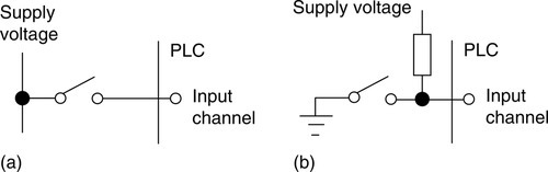
Workpiece present: 1
The 1 level might correspond to a 24 V DC input, the 0 to a 0 V input.
With the arrangement shown in Figure 2.3b, when the switch is open the supply voltage is applied to the PLC input; when the switch is closed the input voltage drops to a low value. The logic levels are thus:
Workpiece present: 0
Switches are available with normally open (NO) or normally closed (NC) contacts or can be configured as either by choice of the relevant contacts. An NO switch has its contacts open in the absence of a mechanical input and the mechanical input is used to close the switch. An NC switch has its contacts closed in the absence of a mechanical input and the mechanical input is used to open the switch. Mechanical switches are specified in terms of number of poles, that is, the number of separate circuits that can be completed by the same switching action, and number of throws, that is, the number of individual contacts for each pole.
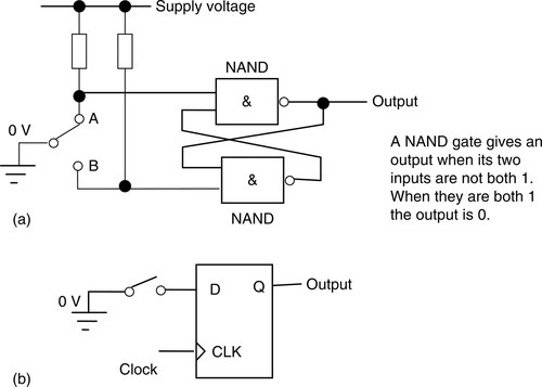
A problem with mechanical switches is that when a switch is closed or opened, bounce can occur and the contacts do not make or open cleanly. Because they involve an elastic member, they bounce back and forth like an oscillating spring. This “bounce” may produce amplitudes that change logic levels over perhaps 20 ms, and so a single switch change may give rise to a number of signals rather than just the required single one. There are a number of ways of eliminating these spurious signals. One way is to include in the software program a delay of approximately 20 ms after the first detected signal transition before any further signals are read. A possibility for a single pole/double throw (SPDT) switch is to use two NAND logic gates (see Chapters 3 and 5), as illustrated in Figure 2.4a. When the switch is in position A, the output is a logic 1. When the switch moves to position B, the output becomes logic 0 and remains latched at this spot, even when the switch bounces. Figure 2.4b shows how a D flip-flop (see Chapter 3 for a discussion) can be used to debounce a single pole/single throw (SPST) switch. The output of the D flip-flop does not change until a position-edged clock signal is imposed, and if this is greater than the bounce time, the output is debounced.
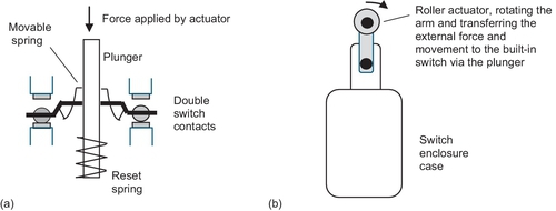
The term limit switch applies to a switch that is used to detect the presence or absence of an object, the passage of a moving part and when an object has reached its end of travel. Because they were first used to determine the limit of travel of an object, they became known as limit switches. They are widely used as they are rugged, reliable and easily installed. The basic part of such a switch is a built-in electrical switch which is switched on or off by means of a plunger; the movement of this plunger being controlled by the actuator head of the limit switch which transfers the external force and movement to the built-in switch (Figure 2.5a). Depending on the object and movement being detected, the actuator head can take a number of forms. A common form is a roller rotating an arm to activate the switch contacts and having a spring return (Figure 2.5b).
As an illustration of the types of limit switches commercially available, the following are some of the general purpose switches marketed by Rockwell Automation. The 801 line of limit switches are general purpose for use in a wide variety of applications and a range of different contact arrangements are available. For a roller lever the contact operation can be slow action with spring return, snap action with spring return, ratchet type maintained or snap action maintained. With snap action, movement of the actuator creates a fast change in contact state once the actuator has reached the operating position, with the slow action relay the contacts are operated at a speed proportional to the speed of operation of the actuator. With the ratchet type of relay, when the lever is moved to the right, contacts are operated. The lever is spring return but the contacts remain in the operated position until the next movement of the roller lever. The snap action maintained type has contact operation when the lever is moved in one direction and restored when the lever is moved in the opposite direction. With the switches the angle through which the lever has to be rotated to activate the switch can be selected and can range from just a few degrees to about 25°.
Omron Industrial Automation also has a range of limit switches. For example, the D4CC miniature limit switches are available in a number of forms: with pin plunger, roller plunger, cross roller plunger, a high sensitive roller plunger, a sealed pin plunger, a sealed roller plunger, sealed cross roller plunger, a plastic rod, and a center roller lever.
As an illustration of the type of task that limit switches are used for, consider the movement of a lift between floors. A limit switch can be used at the floor level to detect the presence of the lift by the actuator head of the switch being actuated by the presence of the lift and so providing a signal which can be used to switch the lift motor on or off.
Liquid-level switches are used to control the level of liquids in tanks. Essentially, these are vertical floats that move with the liquid level, and this movement is used to operate switch contacts.
2.1.2 Proximity Switches
Proximity switches are used to detect the presence of an item without making contact with it. There are a number of forms of such switches, some being suitable only for metallic objects.
The eddy current type of proximity switch has a coil that is energized by a constant alternating current and produces a constant alternating magnetic field. When a metallic object is close to it, eddy currents are induced in it (Figure 2.6a). The magnetic field due to these eddy currents induces an EMF back in the coil with the result that the voltage amplitude needed to maintain the constant coil current changes. The voltage amplitude is thus a measure of the proximity of metallic objects. The voltage can be used to activate an electronic switch circuit, basically a transistor that has its output switched from low to high by the voltage change, creating an on/off device. The range over which such objects can be detected is typically about 0.5 to 20 mm.
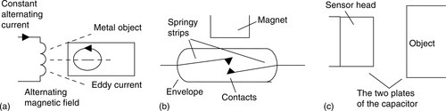
Another switch type is the reed switch. This consists of two overlapping, but not touching, strips of a springy ferromagnetic material sealed in a glass or plastic envelope (Figure 2.6b). When a magnet or current-carrying coil is brought close to the switch, the strips become magnetized and attract each other. The contacts then close. The magnet closes the contacts when it is typically about 1 mm from the switch. Such a switch is widely used with burglar alarms to detect when a door is opened, with the magnet being in the door and the reed switch in the frame of the door. When the door opens, the switch opens.
A proximity switch that can be used with metallic and nonmetallic objects is the capacitive proximity switch. The capacitance of a pair of plates separated by some distance depends on the separation; the smaller the separation, the higher the capacitance. The sensor of the capacitive proximity switch is just one of the plates of the capacitor, the other plate being the metal object for which the proximity is to be detected (Figure 2.6c). Thus the proximity of the object is detected by a change in capacitance. The sensor can also be used to detect nonmetallic objects, since the capacitance of a capacitor depends on the dielectric between its plates. In this case the plates are the sensor and the earth and the nonmetallic object is the dielectric. The change in capacitance can be used to activate an electronic switch circuit and so create an on/off device. Capacitive proximity switches can be used to detect objects when they are typically between 4 mm and 60 mm from the sensor head. An example of the use of such a sensor might be to determine whether a cake is present inside a cardboard box, when such boxes move along a conveyor belt.
As an example of such a sensor, the Omron E2K-X capacitive sensor can be used with a wide range of metallic and non-metallic objects, e.g. glass, wood, and plastic, at distances between 3 and 30 mm. Capacitive proximity sensors also find applications as touch sensors in user interfaces such as computer touch pads and mobile phone touch screens. Such capacitive touch screens consist of an insulator such as glass which is coated with a transparent conductor. As the human body is an electrical conductor, when the surface of the screen is touched there is in a change in capacitance (see Wikipedia for more information).
Another type, the inductive proximity switch, consists of a coil wound a round a ferrous metallic core. When one end of this core is placed near a ferrous metal object, there is effectively a change in the amount of metallic core associated with the coil and so a change in its inductance. This change can be monitored using a resonant circuit, the presence of the ferrous metal object thus changing the current in that circuit. The current can be used to activate an electronic switch circuit and so create an on/off device. The range over which such objects can be detected is typically about 2 mm to 15 mm. An example of the use of such a sensor is to detect whether bottles passing along a conveyor belt have metal caps on. As an example, the Omron E2F sensor can be used to detect metallic objects up to 8 mm away.
2.1.3 Photoelectric Sensors and Switches
Photoelectric switch devices can either operate as transmissive types, in which the object being detected breaks a beam of light, usually infrared radiation, and stops it reaching the detector (Figure 2.7a), as in Figure 2.7b, which shows a U-shaped form in which the object breaks the light beam; or reflective types, in which the object being detected reflects a beam of light onto the detector (Figure 2.7c). The transmissive form of sensor is typically used in applications involving the counting of parts moving along conveyor belts and breaking the light beam; the reflective form is used to detect whether transparent containers contain liquids to the required level.
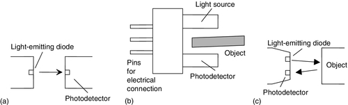
The radiation emitter is generally a light-emitting diode (LED). The radiation detector might be a phototransistor, often a pair of transistors, known as a Darlington pair, to increase the sensitivity. Depending on the circuit used, the output can be made to switch to either high or low when light strikes the transistor. Such sensors are supplied as packages for sensing the presence of objects at close range, typically less than about 5 mm. Another possible detector is a photodiode. Depending on the circuit used, the output can be made to switch to either high or low when light strikes the diode. Yet another possibility is a photoconductive cell. The resistance of the photoconductive cell, often cadmium sulfide, depends on the intensity of the light falling on it.
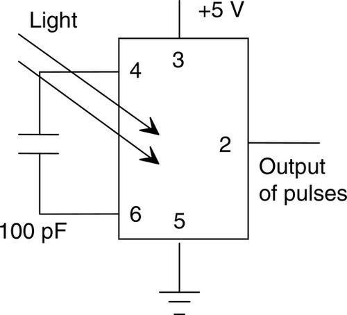
With these sensors, light is converted to a current, voltage, or resistance change. If the output is to be used as a measure of the intensity of the light, rather than just the presence or absence of some object in the light path, the signal will need amplification and then conversion from analog to digital by an analog-to-digital converter. An alternative is to use a light-to-frequency converter, the light then being converted to a sequence of pulses, with the frequency of the pulses being a measure of the light intensity. Integrated circuit sensors, such as the Texas Instrument TSL220, incorporate the light sensor and the voltage-to-frequency converter (Figure 2.8).
2.1.4 Encoders
The term encoder is used for a device that provides a digital output as a result of angular or linear displacement. An incremental encoder detects changes in angular or linear displacement from some datum position; an absolute encoder gives the actual angular or linear position.
Figure 2.9 shows the basic form of an incremental encoder for the measurement of angular displacement. A beam of light, perhaps from an LED, passes through slots in a disc and is detected by a light sensor, such as a photodiode or phototransistor. When the disc rotates, the light beam is alternately transmitted and stopped, and so a pulsed output is produced from the light sensor. The number of pulses is proportional to the angle through which the disc has rotated, the resolution being proportional to the number of slots on a disc. With 60 slots, then, since one revolution is a rotation of 360°, a movement from one slot to the next is a rotation of 6°. By using offset slots it is possible to have over a thousand slots for one revolution and thus a much higher resolution.
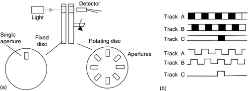
This setup with just one track is a very basic form of incremental encoder with no way of determining the direction of rotation. With a single track, the output is the same for both directions of rotation. Thus, generally such encoders have two or three tracks with sensors (Figure 2.9b). With two tracks, one track is one-quarter of a cycle displaced from the other track. As a consequence, the output from one track will lead or lag that from the other track, depending on the direction of rotation. A third track of just a single aperture is also included; this gives one pulse per revolution and so can be used for counting the number of full revolutions.
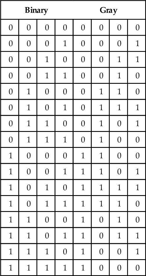
The absolute encoder differs from the incremental encoder in having a pattern of slots that uniquely defines each angular position. With the form shown in Figure 2.10, the rotating disc has four concentric circles of slots and four sensors to detect the light pulses. The slots are arranged in such a way that the sequential output from the sensors is a number in the binary code, each number corresponding to a particular angular position. With four tracks there will be 4 bits, and so the number of positions that can be detected is 24 = 16, that is, a resolution of 360/16 = 22.5°. Typical encoders have up to 10 or 12 tracks. The number of bits in the binary number will be equal to the number of tracks. Thus with 10 tracks there will be 10 bits, and so the number of positions that can be detected is 210, that is, 1024, a resolution of 360/1024 = 0.35°.

Though the normal form of binary code is shown in the figure, in practice a modified form of binary code called the Gray code is generally used. This, unlike normal binary, has only 1 bit that changes in moving from one number to the next (see Table 2.1). This code provides data with the least uncertainty, but since we are likely to need to run systems with binary code, a circuit to convert Gray to binary code has to be used.
2.1.5 Temperature Sensors
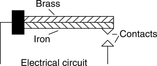
A simple form of temperature sensor that can be used to provide an on/off signal when a particular temperature is reached is the bimetal element. This consists of two strips of different metals, such as brass and iron, bonded together (Figure 2.11). The two metals have different coefficients of expansion. Thus, when the temperature of the bimetal strip increases, the strip curves in order that one of the metals can expand more than the other. The higher expansion metal is on the outside of the curve. As the strip cools, the bending effect is reversed. This movement of the strip can be used to make or break electrical contacts and hence, at some particular temperature, give an on/off current in an electrical circuit. The device is not very accurate but is commonly used in domestic central heating thermostats because it is a very simple, robust device.
Another form of temperature sensor is the resistive temperature detector (RTD). The electrical resistance of metals or semiconductors changes with temperature. In the case of a metal, the ones most commonly used are platinum, nickel, or nickel alloys. Such detectors can be used as one arm of a Wheatstone bridge and the output of the bridge taken as a measure of the temperature (Figure 2.12a). For such a bridge, there is no output when the resistors in the bridge arms are such that P/Q = R/S. Any departure of a resistance from this balance value results in an output. The resistance varies in a linear manner with temperature over a wide range of temperatures, though the actual change in resistance per degree is fairly small. A problem with a resistance thermometer is that the leads connecting it to the bridge can be quite long and themselves have significant resistance, which changes with temperature. One way of overcoming this problem is to use a three-wire circuit, as shown in Figure 2.12b. Then changes in lead resistance affect two arms of the bridge and balance out. Such detectors are very stable and very accurate, though expensive. They are available in the form of wire-wound elements inside ceramic tubes or as thin film elements deposited on a suitable substrate.

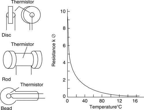
Semiconductors, such as thermistors (Figure 2.13), show very large changes in resistance with temperature. The change, however, is nonlinear. Those specified as NTC have negative temperature coefficients, that is, the resistance decreases with increasing temperature, and those specified as PTC have positive temperature coefficients, that is, the resistance increases with increasing temperature. They can be used with a Wheatstone bridge, but another possibility that is widely used is to employ a potential divider circuit with the change in resistance of the thermistor changing the voltage drop across a resistor (Figure 2.12c). The output from either type of circuit is an analog signal that is a measure of the temperature. Thermistors have the advantages of being cheap and small, giving large changes in resistance, and having fast reaction to temperature changes, though they have the disadvantage of being nonlinear, with limited temperature ranges.
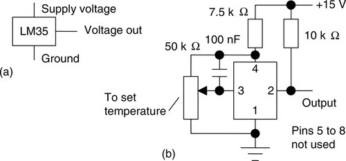
Thermodiodes and thermotransistors are used as temperature sensors since the rate at which electrons and holes diffuse across semiconductor junctions is affected by the temperature. Integrated circuits can combine such a temperature-sensitive element with the relevant circuitry to give an output voltage related to temperature. A widely used integrated package is the LM35, which gives an output of 10 mV/ °C when the supply voltage is +5 V (Figure 2.14a). A digital temperature switch can be produced with an analog sensor by feeding the analog output into a comparator amplifier, which compares it with some set value, producing an output that gives a logic 1 signal when the temperature voltage input is equal to or greater than the set point and otherwise gives a logic 0 signal. Integrated circuits, such as LM3911N, are available, combining a thermotransistor temperature-sensitive element with an operational amplifier. When the connections to the chip are so made that the amplifier is connected as a comparator (Figure 2.14b), the output will switch as the temperature traverses the set point and so directly give an on/off temperature controller. Such temperature sensors have the advantages of being cheap and giving a reasonably linear response. However, they have the disadvantage of a limited temperature range.
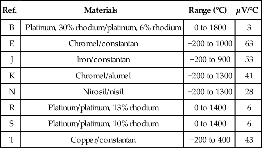
Another commonly used temperature sensor is the thermocouple. The thermocouple consists essentially of two dissimilar wires, A and B, forming a junction (Figure 2.15). When the junction is heated so that it is at a higher temperature than the other junctions in the circuit, which remain at a constant cold temperature, an EMF is produced that is related to the hot junction temperature. The EMF values for a thermocouple are given in Table 2.2, assuming that the cold junction is at 0°C. The thermocouple voltage is small and needs amplification before it can be fed to the analog channel input of a PLC. There is also circuitry required to compensate for the temperature of the cold junction, since often it will not be at 0°C, but room temperature and its temperature affects the value of the EMF. The amplification and compensation, together with filters to reduce the effect of interference from the mains supply, are often combined in a signal processing unit. Thermocouples have the advantages of being able to sense the temperature at almost any point, ruggedness, and being able to operate over a large temperature range. They have the disadvantages of giving a nonlinear response, giving only small changes in EMF per degree change in temperature, and requiring temperature compensation for the cold junction.
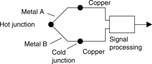
Table 2.2
Thermocouples
| Ref. | Materials | Range (°C) | μV/°C |
| B | Platinum, 30% rhodium/platinum, 6% rhodium | 0 to 1800 | 3 |
| E | Chromel/constantan | −200 to 1000 | 63 |
| J | Iron/constantan | −200 to 900 | 53 |
| K | Chromel/alumel | −200 to 1300 | 41 |
| N | Nirosil/nisil | −200 to 1300 | 28 |
| R | Platinum/platinum, 13% rhodium | 0 to 1400 | 6 |
| S | Platinum/platinum, 10% rhodium | 0 to 1400 | 6 |
| T | Copper/constantan | −200 to 400 | 43 |
2.1.6 Position/Displacement Sensors
The term position sensor is used for a sensor that gives a measure of the distance between a reference point and the current location of the target, while a displacement sensor gives a measure of the distance between the present position of the target and the previously recorded position.
Resistive linear and angular position sensors are widely used and relatively inexpensive. These are also called linear and rotary potentiometers. A DC voltage is provided across the full length of the track and the voltage signal between a contact that slides over the resistance track and one end of the track is related to the position of the sliding contact between the ends of the potentiometer resistance track (Figure 2.16). The potentiometer thus provides an analog linear or angular position sensor.

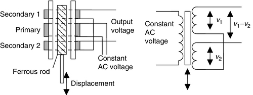
Another form of displacement sensor is the linear variable differential transformer (LVDT), which gives a voltage output related to the position of a ferrous rod. The LVDT consists of three symmetrically placed coils through which the ferrous rod moves (Figure 2.17). When an alternating current is applied to the primary coil, alternating voltages, v1 and v2, are induced in the two secondary coils. When the ferrous rod core is centered between the two secondary coils, the voltages induced in them are equal. The outputs from the two secondary coils are connected so that their combined output is the difference between the two voltages, that is, v1 – v2. With the rod central, the two alternating voltages are equal and so there is no output voltage. When the rod is displaced from its central position, there is more of the rod in one secondary coil than the other. As a result, the size of the alternating voltage induced in one coil is greater than that in the other. The difference between the two secondary coil voltages, that is, the output, thus depends on the position of the ferrous rod. The output from the LVDT is an alternating voltage. This is usually converted to an analog DC voltage and amplified before inputting to the analog channel of a PLC.
Capacitive displacement sensors are essentially just parallel plate capacitors. The capacitance will change if the plate separation changes, the area of overlap of the plates changes, or a slab of dielectric is moved into or out of the plates (Figure 2.18). All these methods can be used to give linear displacement sensors. The change in capacitance has to be converted into a suitable electrical signal by signal conditioning.
2.1.7 Strain Gauges
When a wire or strip of semiconductor is stretched, its resistance changes. The fractional change in resistance is proportional to the fractional change in length, that is, strain.

where ΔR is the change in resistance for a wire of resistance R and G is a constant called the gauge factor. For metals, the gauge factor is about 2; for semiconductors, about 100. Metal resistance strain gauges are in the form of a flat coil so that they get a reasonable length of metal in a small area. Often they are etched from metal foil (Figure 2.19a) and attached to a backing of thin plastic film so that they can be stuck on surfaces, like postage stamps on an envelope. The change in resistance of the strain gauge, when subject to strain, is usually converted into a voltage signal by the use of a Wheatstone bridge. A problem that occurs is that the resistance of the strain gauge also changes with temperature, and thus some means of temperature compensation has to be used so that the output of the bridge is only a function of the strain. This can be achieved by placing a dummy strain gauge in an opposite arm of the bridge, that gauge not being subject to any strain but only the temperature (Figure 2.19b). A popular alternative is to use four active gauges as the arms of the bridge and arrange them so that one pair of opposite gauges is in tension and the other pair in compression. This not only gives temperature compensation; it also gives a much larger output change when strain is applied. The following paragraph illustrates systems employing such a form of compensation.

By attaching strain gauges to other devices, changes that result in strain of those devices can be transformed, by the strain gauges, to give voltage changes. They might, for example, be attached to a cantilever to which forces are applied at its free end (Figure 2.19c). The voltage change, resulting from the strain gauges and the Wheatstone bridge, then becomes a measure of the force. Another possibility is to attach strain gauges to a diaphragm, which deforms as a result of pressure (Figure 2.19d). The output from the gauges and associated Wheatstone bridge then becomes a measure of the pressure.
2.1.8 Pressure Sensors
Pressure sensors can be designed to give outputs that are proportional to the difference in pressure between two input ports. If one of the ports is left open to the atmosphere, the gauge measures pressure changes with respect to the atmosphere and the pressure measured is known as gauge pressure. The pressure is termed the absolute pressure if it is measured with respect to a vacuum. Commonly used pressure sensors that give responses related to the pressure are diaphragm and bellows types. The diaphragm type consists of a thin disc of metal or plastic, secured around its edges. When there is a pressure difference between the two sides of the diaphragm, its center deflects. The amount of deflection is related to the pressure difference. This deflection may be detected by strain gauges attached to the diaphragm (see Figure 2.19d), by a change in capacitance between it and a parallel fixed plate, or by using the deflection to squeeze a piezoelectric crystal (Figure 2.20a).
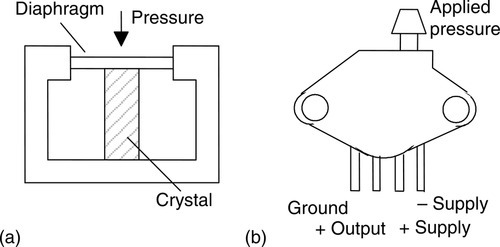
When a piezoelectric crystal is squeezed, there is a relative displacement of positive and negative charges within the crystal and the outer surfaces of the crystal become charged. Hence a potential difference appears across it. An example of such a sensor is the Motorola MPX100AP sensor (Figure 2.20b). This has a built-in vacuum on one side of the diaphragm and so the deflection of the diaphragm gives a measure of the absolute pressure applied to the other side of the diaphragm. The output is a voltage that is proportional to the applied pressure, with a sensitivity of 0.6 mV/kPa. Other versions are available that have one side of the diaphragm open to the atmosphere and so can be used to measure gauge pressure; others allow pressure to be applied to both sides of the diaphragm and so can be used to measure differential pressures.
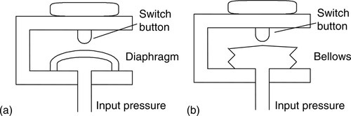
Pressure switches are designed to switch on or off at a particular pressure. A typical form involves a diaphragm or bellows that moves under the action of the pressure and operates a mechanical switch. Figure 2.21 shows two possible forms. Diaphragms are less sensitive than bellows but can withstand greater pressures.
2.1.9 Liquid-Level Detectors
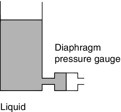
Pressure sensors may be used to monitor the depth of a liquid in a tank. The pressure due to a height of liquid h above some level is hρg, where ρ is the density of the liquid and g the acceleration due to gravity. Thus a commonly used method of determining the level of liquid in a tank is to measure the pressure due to the liquid above some datum level (Figure 2.22).
Often a sensor is just required to give a signal when the level in some container reaches a particular level. A float switch that is used for this purpose consists of a float containing a magnet that moves in a housing with a reed switch. As the float rises or falls, it turns the reed switch on or off, the reed switch being connected in a circuit that then switches a voltage on or off.
2.1.10 Fluid Flow Measurement
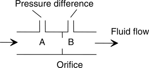
A common form of fluid flow meter is one based on measuring the difference in pressure that results when a fluid flows through a constriction. Figure 2.23 shows a commonly used form, the orifice flow meter. As a result of the fluid flowing through the orifice, the pressure at A is higher than that at B, the difference in pressure being a measure of the rate of flow. This pressure difference can be monitored by means of a diaphragm pressure gauge and thus becomes a measure of the rate of flow.
2.1.11 Ultrasonic Proximity Sensors
Ultrasonic proximity sensors direct ultrasonic sound waves (i.e. high frequency sound waves beyond the audible frequencies) to a target and measure the time taken for the sound waves to return; the further away the object the greater the time taken. Such sensors are used for distances to a target of the order of a few centimeters to a meter. The Omron E4C-DS30 ultrasonic proximity sensor has a range of 50–300 mm, the E4C-DS80 has 70–800 mm, and the E4C-DS100 sensor 90–1000 mm. Ideally, the target object should have a flat smooth surface to give a good reflection, as uneven or curved surfaces give a poorer reflection and so the ultrasonic proximity sensor must be positioned closer to such objects. Soft materials, e.g. foam, do not reflect sound waves well enough to be able to be detected. As an indicator of the variety of applications that the Omron sensors can be used for, they give detection of transparent trays, inspection of solvent tank levels, detection of sheet sag, detection of tires on a conveyor belt, detection of rubber sheet sag between supporting rollers and detection of the position of glass substrates in cassettes.
2.1.12 Smart Sensors
To use a sensor, we generally need to add signal conditioning circuitry, such as circuits which amplify and convert from analog to digital, to get the sensor signal in the right form, take account of any nonlinearities, and calibrate it. Additionally, we need to take account of drift, that is, a gradual change in the properties of a sensor over time. Some sensors have all these elements taken care of in a single package; they are called smart sensors.
The term smart sensor is thus used in discussing a sensor that is integrated with the required buffering and conditioning circuitry in a single element and provides functions beyond that of just a sensor. The circuitry with the element usually consists of data converters, a processor and firmware, and some form of nonvolatile electrically erasable programmable read only memory (EEPROM, which is similar to EPROM). The term nonvolatile is used because the memory has to retain certain parameters when the power supply is removed. Such smart sensors can have all their elements produced on a single silicon chip. Because the elements are processor-based devices, such a sensor can be programmed for specific requirements. For example, it can be programmed to process the raw input data, correcting for such things as nonlinearities, and then send the processed data to a base station. It can be programmed to send a warning signal when the measured parameter reaches some critical value.
The IEEE 1451.4 standard interface for smart sensors and actuators is based on an electronic data sheet (TEDS) format that is aimed at allowing installed analog transducers to be easily connected to digital measurement systems. The standard requires the nonvolatile EEPROM embedded memory to hold and communicate data, which will allow a plug-and-play capability. It thus would hold data for the identification and properties for the sensor and might also contain the calibration template, thus facilitating digital interrogation.
2.1.13 Sensors Ranges
To give some idea of the range of sensors that are used in control systems, the following is part of the extensive list of sensors available from Rockwell Automation for such applications:
• Condition sensors: give information to enable automatic sequencing of equipment. These include pressure sensors, temperature sensors, level sensors, flow switches and speed sensing switches.
• Presence sensing sensors: detect the distance, absence or presence of an object and include inductive proximity sensors, capacitive proximity sensors, ultrasonic sensors and photoelectric sensors. Photoelectric sensors are available for such applications as the detection of clear materials such as glass and plastic bottles, also with the use of filters to detect changes in color. Fibre optic sensors, consisting of a light sensor at the end of a fibre optic cable, can be used for packaging applications where the detection of very small objects is required.
• Limit sensors: electromechanical devices that consist of an actuator linked to a set of contacts so when an object comes into contact with the actuator, the device operates its contact to either make or break an electrical circuit.
• Safety interlock switches: used as a means for safeguarding plant by shutting off power, controlling personnel access and preventing a machine from starting when the safety guard is open.
2.2 Output Devices
The output ports of a PLC are relay or optoisolator with transistor or triac, depending on the devices that are to be switched on or off. Generally, the digital signal from an output channel of a PLC is used to control an actuator, which in turn controls some process. The term actuator is used for the device that transforms the electrical signal into some more powerful action, which then results in control of the process. The following are some examples.
2.2.1 Relay
When a current passes through a solenoid, a magnetic field is produced; this can then attract ferrous metal components in its vicinity. With the relay, this attraction is used to operate a switch. Relays can thus be used to control a larger current or voltage and, additionally, to isolate the power used to initiate the switching action from that of the controlled power. For a relay connected to the output of a PLC, when the output switches on, the solenoid magnetic field is produced, and this pulls on the contacts and so closes a switch or switches (Figure 2.24). The result is that much larger currents can be switched on. Thus the relay might be used to switch on the current to a motor. The solenoid of a relay might be used to operate more than one set of contacts, the term pole being used for each set of contacts. Contacts can also be obtained as, in the absence of any input, either normally open (NO) or normally closed (NC). Thus, when selecting relays for a particular application, consideration has to be given to the number of poles required, the initial contact conditions, and the rated voltage and current.

The term latching relay is used for a relay whose contacts remain open or closed even after the power has been removed from the solenoid. The term contactor is used when large currents are being switched from large voltage sources.
2.2.2 Directional Control Valves
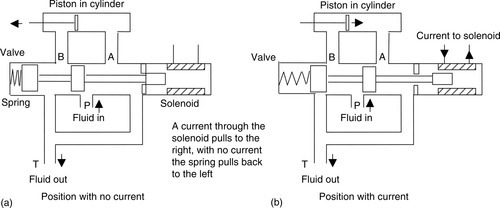
Another example of the use of a solenoid as an actuator is a solenoid operated valve. The valve may be used to control the directions of flow of pressurized air or oil and so used to operate other devices, such as a piston moving in a cylinder. Figure 2.25 shows one such form, a spool valve, used to control the movement of a piston in a cylinder. Pressurized air or hydraulic fluid is input from port P, which is connected to the pressure supply from a pump or compressor, and port T is connected to allow hydraulic fluid to return to the supply tank or, in the case of a pneumatic system, to vent the air to the atmosphere. With no current through the solenoid (Figure 2.25a), the hydraulic fluid or pressurized air is fed to the right of the piston and exhausted from the left, the result then being the movement of the piston to the left. When a current is passed through the solenoid, the spool valve switches the hydraulic fluid or pressurized air to the left of the piston and exhausts it from the right. The piston then moves to the right. The movement of the piston might be used to push a deflector to deflect items off a conveyor belt (refer back to Figure 1.1b) or implement some other form of displacement that requires power.
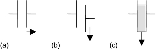
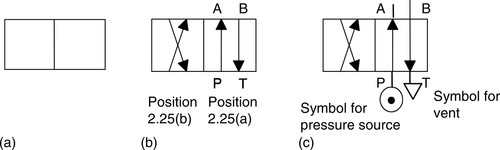
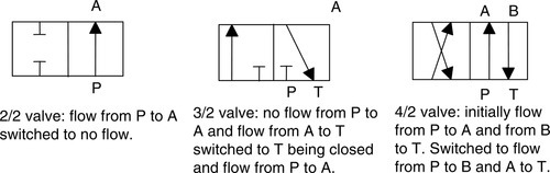
With the preceding valve the two control positions are shown in Figures 2.25a and 2.25b. Directional control valves are described by the number of ports and the number of control positions they contain. The valve shown in Figure 2.25 has four ports—A, B, P, and T—and two control positions. It is thus referred to as a 4/2 valve. The basic symbol used on drawings for valves is a square, with one square used to describe each of the control positions. Thus the symbol for the valve in Figure 2.25 consists of two squares (Figure 2.26a). Within each square the switching positions are then described by arrows to indicate a flow direction, or a terminated line to indicate no flow path (Figure 2.26b). Pipe connections, that is, the inlet and output ports, for a valve are indicated by lines drawn outside the box and are drawn for just the box representing the unactuated or rest position for the valve. Figure 2.26c shows this for the valve shown in Figure 2.25. Figure 2.27 shows more examples of direction valves and their switching positions.
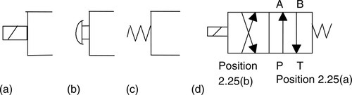
In diagrams, the actuation methods used with valves are added to the symbol; Figure 2.28 shows examples of such symbols. The valve shown in Figure 2.25 has a spring to give one position and a solenoid to give the other, so the symbol is as shown in Figure 2.28d.
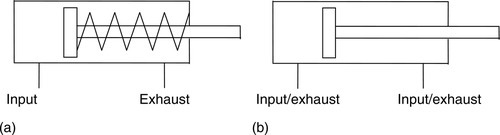
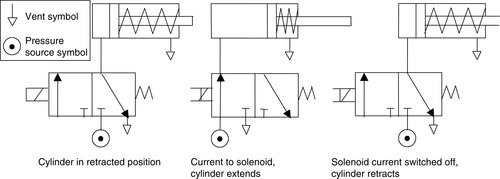
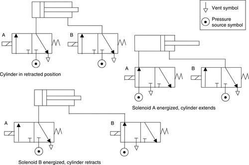
Direction valves can be used to control the direction of motion of pistons in cylinders, the displacement of the pistons being used to implement the required actions. The term single-acting cylinder (Figure 2.29a) is used for one that is powered by the pressurized fluid being applied to one side of the piston to give motion in one direction, which is returned in the other direction, possibly by an internal spring. The term double-acting cylinder (Figure 2.29b) is used when the cylinder is powered by fluid for its motion in both piston movement directions. Figure 2.30 shows how a valve can be used to control the direction of motion of a piston in a single-acting cylinder; Figure 2.31 shows how two valves can be used to control the action of a piston in a double-acting cylinder.
2.2.3 Motors
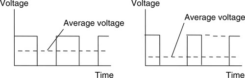
A DC motor has coils of wire mounted in slots on a cylinder of ferromagnetic material, which is termed the armature. The armature is mounted on bearings and is free to rotate. It is mounted in the magnetic field produced by permanent magnets or current passing through coils of wire, which are called the field coils. When a current passes through the armature coil, forces act on the coil and result in rotation. Brushes and a commutator are used to reverse the current through the coil every half rotation and so keep the coil rotating. The speed of rotation can be changed by changing the size of the current to the armature coil. However, because fixed voltage supplies are generally used as the input to the coils, the required variable current is often obtained by an electronic circuit. This can control the average value of the voltage, and hence current, by varying the time for which the constant DC voltage is switched on (Figure 2.32). The term pulse width modulation (PWM) is used because the width of the voltage pulses is used to control the average DC voltage applied to the armature. A PLC might thus control the speed of rotation of a motor by controlling the electronic circuit used to control the width of the voltage pulses.
Many industrial processes only require the PLC to switch a DC motor on or off. This might be done using a relay. Figure 2.33a shows the basic principle. The diode is included to dissipate the induced current resulting from the back EMF.
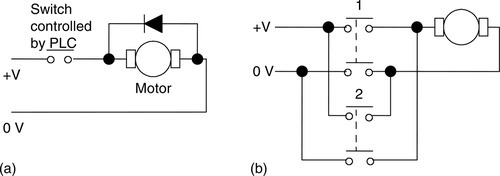
Sometimes a PLC is required to reverse the direction of rotation of the motor. This can be done using relays to reverse the direction of the current applied to the armature coil. Figure 2.33b shows the basic principle. For rotation in one direction, switch 1 is closed and switch 2 opened. For rotation in the other direction, switch 1 is opened and switch 2 closed.
Another form of DC motor is the brushless DC motor. This uses a permanent magnet for the magnetic field, but instead of the armature coil rotating as a result of the magnetic field of the magnet, the permanent magnet rotates within the stationary coil. With the conventional DC motor, a commutator has to be used to reverse the current through the coil every half rotation to keep the coil rotating in the same direction. With the brushless permanent magnet motor, electronic circuitry is used to reverse the current. The motor can be started and stopped by controlling the current to the stationary coil. Reversing the motor is more difficult, as reversing the current is not so easy, due to the electronic circuitry used for the commutator function. One method that is used is to incorporate sensors with the motor to detect the position of the north and south poles. These sensors can then cause the current to the coils to be switched at just the right moment to reverse the forces applied to the magnet. The speed of rotation can be controlled using pulse width modulation, that is, controlling the average value of pulses of a constant DC voltage.
Though AC motors are cheaper, more rugged, and more reliable than DC motors, maintaining constant speed and controlling that speed is generally more complex than with DC motors. As a consequence, DC motors, particularly brushless permanent magnet motors, tend to be more widely used for control purposes.
2.2.4 Stepper Motors
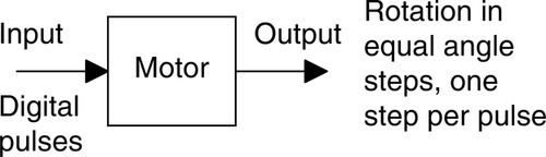
The stepper or stepping motor is a motor that produces rotation through equal angles, the so-called steps, for each digital pulse supplied to its input (Figure 2.34). Thus, if one input pulse produces a rotation of 1.8°, then 20 such pulses would give a rotation of 36.0°. To obtain one complete revolution through 360°, 200 digital pulses would be required. The motor can thus be used for accurate angular positioning.
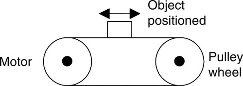
If a stepping motor is used to drive a continuous belt (Figure 2.35), it can be used to give accurate linear positioning. Such a motor is used with computer printers, robots, machine tools, and a wide range of instruments for which accurate positioning is required.
There are two basic forms of stepper motor: the permanent magnet type, with a permanent magnet rotor, and the variable reluctance type, with a soft steel rotor. There is also a hybrid form combining both the permanent magnet and variable reluctance types. The most common type is the permanent magnet form.
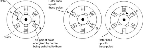
Figure 2.36 shows the basic elements of the permanent magnet type with two pairs of stator poles. Each pole is activated by a current being passed through the appropriate field winding, the coils being such that opposite poles are produced on opposite coils. The current is supplied from a DC source to the windings through switches. With the currents switched through the coils such that the poles are as shown in Figure 2.36, the rotor will move to line up with the next pair of poles and stop there. This would be a rotation of 90°. If the current is then switched so that the polarities are reversed, the rotor will move a step to line up with the next pair of poles, at angle 180°, and stop there. The polarities associated with each step are as follows:
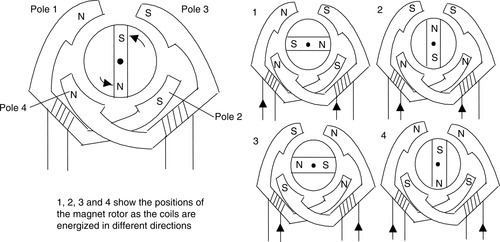
| Step | Pole 1 | Pole 2 | Pole 3 | Pole 4 |
| 1 | North | South | South | North |
| 2 | South | North | South | North |
| 3 | South | North | North | South |
| 4 | North | South | North | South |
| 5 | Repeat of steps 1 to 4 | |||
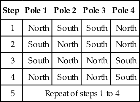
Thus in this case there are four possible rotor positions: 0°, 90°, 180°, and 270°.
Figure 2.37 shows the basic principle of the variable reluctance type. The rotor is made of soft steel and has a number of teeth, the number being less than the number of poles on the stator. The stator has pairs of poles, each pair of which is activated and made into an electromagnet by a current being passed through the coils wrapped round it. When one pair of poles is activated, a magnetic field is produced that attracts the nearest pair of rotor teeth so that the teeth and poles line up. This is termed the position of minimum reluctance. By then switching the current to the next pair of poles, the rotor can be made to rotate to line up with those poles. Thus by sequentially switching the current from one pair of poles to the next, the rotor can be made to rotate in steps.
There is another version of the stepper motor—the hybrid stepper. This version combines features of both the permanent magnet and variable reluctance motors. Hybrid steppers have a permanent magnet rotor encased in iron caps that are cut to have teeth. The rotor sets itself in the minimum reluctance position when a pair of stator coils are energized.
The following are some of the terms commonly used in specifying stepper motors:
• Phase. This term refers to the number of independent windings on the stator. Two-phase motors tend to be used in light-duty applications, three-phase motors tend to be variable reluctance steppers, and four-phase motors tend to be used for higher-power applications.
• Step angle. This is the angle through which the rotor rotates for one switching change for the stator coils.
• Holding torque. This is the maximum torque that can be applied to a powered motor without moving it from its rest position and causing spindle rotation.
• Pull-in torque. This is the maximum torque against which a motor will start, for a given pulse rate, and reach synchronism without losing a step.
• Pull-out torque. This is the maximum torque that can be applied to a motor, running at a given stepping rate, without losing synchronism.
• Pull-in rate. This is the maximum switching rate at which a loaded motor can start without losing a step.
• Pull-out rate. This is the switching rate at which a loaded motor will remain in synchronism as the switching rate is reduced.
• Slew range. This is the range of switching rates between pull-in and pull-out within which the motor runs in synchronism but cannot start up or reverse.
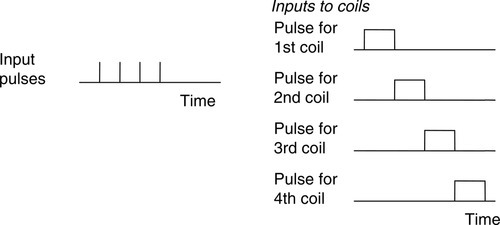
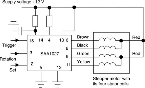
To drive a stepper motor so that it proceeds step by step to provide rotation requires each pair of stator coils to be switched on and off in the required sequence when the input is a sequence of pulses (Figure 2.38). Driver circuits are available to give the correct sequencing. Figure 2.39 shows an example: the SAA 1027 for a four-phase unipolar stepper. Motors are termed unipolar if they are wired so that the current can flow in only one direction through any particular motor terminal; they're called bipolar if the current can flow in either direction through any particular motor terminal. The stepper motor will rotate through one step each time the trigger input goes from low to high. The motor runs clockwise when the rotation input is low and anticlockwise when high. When the set pin is made low, the output resets. In a control system, these input pulses might be supplied by a microprocessor.
2.3 Examples of Applications
The following are some examples of control systems designed to illustrate the use of a range of input and output devices.
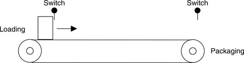
2.3.1 A Conveyor Belt
Consider a conveyor belt that is to be used to transport goods from a loading machine to a packaging area (Figure 2.40). When an item is loaded onto the conveyor belt, a contact switch might be used to indicate that the item is on the belt and to start the conveyor motor. The motor then has to keep running until the item reaches the far end of the conveyor and falls off into the packaging area. When it does this, a switch might be activated that has the effect of switching off the conveyor motor. The motor is then to remain off until the next item is loaded onto the belt. Thus the inputs to a PLC controlling the conveyor are from two switches and the output is to a motor.
2.3.2 A Lift
Consider a simple goods lift to move items from one level to another. For example, it might lift bricks from the ground level to the height where some bricklayers are working. The lift is to move upward when a push button is pressed at the ground level to send the lift upward or a push button is pressed at the upper level to request the lift to move upward, but in both cases there is a condition that has to be met that a limit switch indicates that the access gate to the lift platform is closed. The lift is to move downward when a push button is pressed at the upper level to send the lift downward or a push button is pressed at the lower level to request the lift to move downward, but in both cases there is a condition that has to be met that a limit switch indicates that the access gate to the lift platform is closed. Thus the inputs to the control system are electrical on/off signals from push button switches and limit switches. The output from the control system is the signal to control the motor.
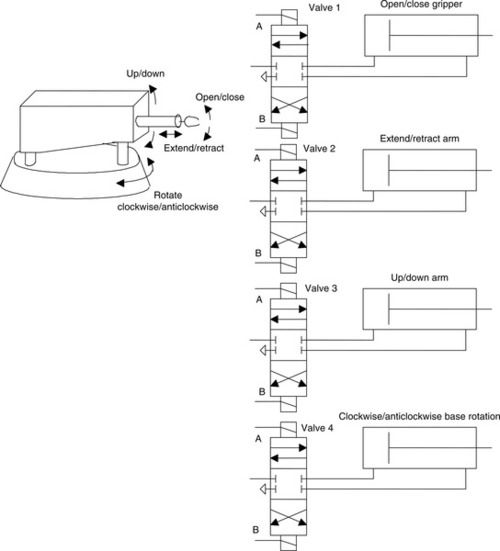
2.3.3 A Robot Control System
Figure 2.41 shows how directional control valves can be used for a control system of a robot. When there is an input to solenoid A of valve 1, the piston moves to the right and causes the gripper to close. If solenoid B is energized with A deenergized, the piston moves to the left and the gripper opens. When both solenoids are deenergized, no air passes to either side of the piston in the cylinder and the piston keeps its position without change. Likewise, inputs to the solenoids of valve 2 are used to extend or retract the arm. Inputs to the solenoids of valve 3 are used to move the arm up or down. Inputs to the solenoids of valve 4 are used to rotate the base in either a clockwise or anticlockwise direction.
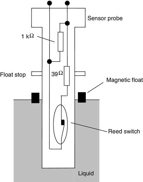
2.3.4 Liquid-Level Monitoring
Figure 2.42 shows a method that could be used to give an on/off signal when the liquid in a container reaches a critical level. A magnetic float, a ring circling the sensor probe, falls as the liquid level falls and opens a reed switch when the critical level is reached. The reed switch is in series with a 39 Ω resistor so that this is switched in parallel with a 1 kΩ resistor by the action of the reed switch. Opening the reed switch thus increases the resistance from about 37 Ω to 1 kΩ. Such a resistance change can be transformed by signal conditioning to give suitable on/off signals.
2.3.5 Packages on Conveyor Belt Systems
In some situations, the requirement is to check whether there is a nontransparent item on the belt at a particular position. This can be done using a light emitter on one side of the belt and a photoelectric sensor on the other, there then being an interruption of the light beam when the item is at the required position. If the item had been transparent, such as a bottle, the photoelectric sensor might have been positioned to pick up reflected light to determine when the item is in the required position.
Summary
The term sensor refers to an input device that provides a usable output in response to a specified input. The term transducer is generally used for a device that converts a signal from one form to a different physical form.
Common terms used to specify the performance of sensors are as follows: Accuracy is the extent to which the value indicated by a measurement system or element might be wrong. Error is the difference between the result of a measurement and the true value. Nonlinearity error is the error that occurs as a result of assuming a linear relationship between input and output. Hysteresis error is the difference in output given for the same measured quantity according to whether that value was reached by a continuously increasing change or a continuously decreasing change. Range consists of the limits between which an input can vary. Response time is the time that elapses after the input is abruptly increased from zero to a constant value up to the time it reaches some specified percentage of the steady-state value. Sensitivity indicates how much the output changes when the quantity being measured changes by a given amount. Stability is a system's ability to give the same output for a given input over a period of time. Repeatability is a system's ability to give the same value for repeated measurements of the same quantity. Reliability is the probability that a system will operate up to an agreed level of performance.
Commonly used sensors are mechanical switches; proximity switches, which may be eddy current, reed, capacitive or inductive; photoelectric, which may be transmissive or reflective types; encoders that give a digital output as a result of angular or linear displacement, incremental encoders measuring angular displacement and absolute encoders giving a binary output that uniquely defines each angular position; temperature sensors such as bimetallic strips, resistive temperature detectors, thermistors, thermodiodes, thermotransistors, or thermocouples; position and displacement sensors such as potentiometers, LVDTs, and capacitive displacement sensors; strain gauges, which give a resistance change when strained; pressure sensors such as diaphragm gauges; liquid-level detectors involving pressure gauges or floats; and fluid flow meters such as the orifice flow meter.
Commonly used output devices include relays, directional control valves with cylinders, DC motors, and stepper motors.
Problems
Problems 1 through 14 have four answer options: A, B, C, or D. Choose the correct answer from the answer options.
1. Decide whether each of these statements is true (T) or false (F). A limit switch:
(i) Can be used to detect the presence of a moving part.
(ii) Is activated by contacts making or breaking an electrical circuit.
A. (i) T (ii) T
B. (i) T (ii) F
C. (i) F (ii) T
D. (i) F (ii) F
2. Decide whether each of these statements is true (T) or false (F). A thermistor is a temperature sensor that gives resistance changes that are:
(i) A nonlinear function of temperature.
(ii) Large for comparatively small temperature changes.
A. (i) T (ii) T
B. (i) T (ii) F
C. (i) F (ii) T
D. (i) F (ii) F
3. A diaphragm pressure sensor is required to give a measure of the gauge pressure present in a system. Such a sensor will need to have a diaphragm with:
B. One side open to the atmosphere.
C. The pressure applied to both sides.
D. A controlled adjustable pressure applied to one side.
4. The change in resistance of an electrical resistance strain gauge with a gauge factor of 2.0 and resistance 100 Ω when subject to a strain of 0.001 is:
B. 0.002 Ω
C. 0.02 Ω
D. 0.2 Ω
5. An incremental shaft encoder gives an output that is a direct measure of:
B. The change in diameter of the shaft.
C. The change in angular position of the shaft.
D. The absolute angular position of the shaft.
6. Decide whether each of these statements is true (T) or false (F). Input devices that give an analog input for displacement include a:
(ii) Linear variable differential transformer.
A. (i) T (ii) T
B. (i) T (ii) F
C. (i) F (ii) T
D. (i) F (ii) F
Problems 7 and 8 refer to Figure 2.43, which shows the symbol for a directional valve.
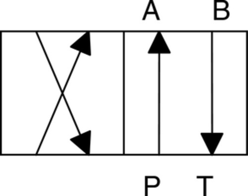
7. Decide whether each of these statements is true (T) or false (F). The valve has:
(ii) 2 positions
A. (i) T (ii) T
B. (i) T (ii) F
C. (i) F (ii) T
D. (i) F (ii) F
8. Decide whether each of these statements is true (T) or false (F). In the control positions:
(i) A is connected to T and P to B.
(ii) P is connected to A and B to T.
A. (i) T (ii) T
B. (i) T (ii) F
C. (i) F (ii) T
D. (i) F (ii) F
9. For the arrangement shown in Figure 2.44, decide whether each of these statements is true (T) or false (F).

(i) When a current passes through the solenoid, the cylinder extends.
(ii) When the current ceases, the cylinder remains extended.
A. (i) T (ii) T
B. (i) T (ii) F
C. (i) F (ii) T
D. (i) F (ii) F
10. For the arrangement shown in Figure 2.45, decide whether each of these statements is true (T) or false (F).
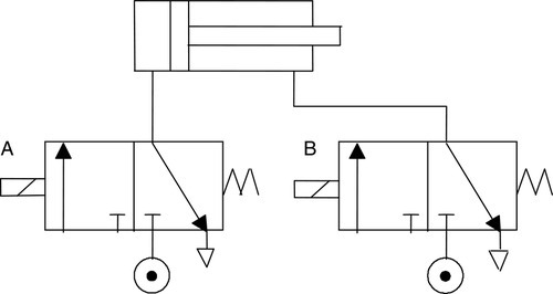
(i) When solenoid A is energized, the cylinder extends.
(ii) When solenoid B is energized, the cylinder extends.
A. (i) T (ii) T
B. (i) T (ii) F
C. (i) F (ii) T
D. (i) F (ii) F
11. For the two 3/2 valves shown in Figure 2.46, decide whether each of these statements is true (T) or false (F).
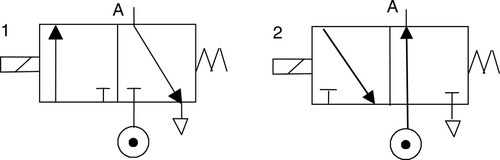
(i) When the solenoid in valve 1 is energized, A is vented.
(ii) When the solenoid in valve 2 is energized, A is vented.
A. (i) T (ii) T
B. (i) T (ii) F
C. (i) F (ii) T
D. (i) F (ii) F
12. Decide whether each of these statements is true (T) or false (F). A stepper motor has a step angle of 1.8°. This means that:
(i) Each pulse input to the motor rotates the motor shaft by 1.8°.
(ii) The motor shaft takes 1 s to rotate through 1.8°.
A. (i) T (ii) T
B. (i) T (ii) F
C. (i) F (ii) T
D. (i) F (ii) F
13. A stepper motor has a step angle of 7.5°. The digital input rate required to produce a rotation of 10 rev/s is:
B. 75 pulses per second
C. 480 pulses per second
D. 750 pulses per second
14. Decide whether each of these statements is true (T) or false (F). A proximity switch is required for detecting the presence of a nonmetallic object. Types of switches that might be suitable are:
(ii) Capacitive type.
A. (i) T (ii) T
B. (i) T (ii) F
C. (i) F (ii) T
D. (i) F (ii) F
15. Explain the operation of the following input devices, stating the form of the signal being sensed and the output: (a) reed switch, (b) incremental shaft encoder, (c) photoelectric transmissive switch, (d) diaphragm pressure switch.
16. Explain how the on/off operation and direction of a DC motor can be controlled by switches.
17. Explain the principle of the stepper motor and state the different types available.
18. Select sensors that might be suitable for the following applications: (a) counting boxes moving along a conveyor belt, (b) verifying the level of milk in a plastic bottle moving along a conveyor belt, (c) determining when the piston in a cylinder has reached a particular point in its extension; (d) determining when a metal plate has reached the right position under a tool.
19. The following is part of the specification of a stepper motor. Explain the significance of the terms: phases 4, step angle 7.5°, current per phase 130 mA, resistance per phase 94 Ω, inductance per phase 43 mH, suitable driver SAA1027.
20. Suggest a way by which a spindle could be controlled to position a mechanism at 5° intervals.
21. A range of opaque bottles of various sizes moves along a conveyor belt. Suggest a method that could be used to (a) detect the different sizes and (b) push bottles off the belt.
Lookup Tasks
22. Look up the specifications of thermistors and select one that might be suitable for monitoring temperatures of about 40°C.
23. Look up the specification of the MPX100AP pressure sensor and write an outline of its possible use and capabilities.
24. Look up the specification of the LM3911N integrated temperature sensor and write an outline of its possible use and capabilities.