IL, SFC, and ST Programming Methods
This chapter continues from the previous chapter and discusses the other IEC 61131-3 programming languages, that is, instruction lists (ILs), sequential function charts (SFCs), and structured text (ST).
6.1 Instruction Lists
A programming method that can be considered to be the entering of a ladder program using text is the instruction list (IL). An instruction list gives programs as a series of instructions, with each instruction on a new line. Each instruction consists of an operator followed by one or more operands, that is, the subjects of the operator. Thus we might have:
to indicate that the operand A is to be loaded, LD being the operator used to indicate loading. In terms of ladder diagrams, an operator may be regarded as a ladder element, and LD is equivalent to starting a rung with open contacts for input A. Another instruction might be:
to indicate that there is to be an output to Q.
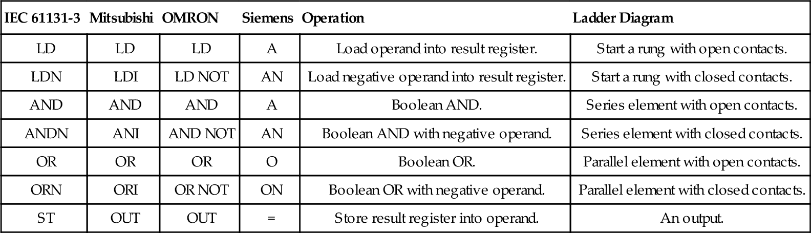
Mnemonic codes are used for operators, each code corresponding to an operator/ladder element. The codes used differ to some extent from manufacturer to manufacturer, though a standard under IEC 61131-3 has been proposed and is being widely adopted. Table 6.1 shows some of the codes used by manufacturers and the proposed standard for instructions used in this chapter (see later chapters for codes for other functions).
Table 6.1
Instruction Code Mnemonics
| IEC 61131-3 | Mitsubishi | OMRON | Siemens | Operation | Ladder Diagram |
| LD | LD | LD | A | Load operand into result register. | Start a rung with open contacts. |
| LDN | LDI | LD NOT | AN | Load negative operand into result register. | Start a rung with closed contacts. |
| AND | AND | AND | A | Boolean AND. | Series element with open contacts. |
| ANDN | ANI | AND NOT | AN | Boolean AND with negative operand. | Series element with closed contacts. |
| OR | OR | OR | O | Boolean OR. | Parallel element with open contacts. |
| ORN | ORI | OR NOT | ON | Boolean OR with negative operand. | Parallel element with closed contacts. |
| ST | OUT | OUT | = | Store result register into operand. | An output. |
Instruction List is a low-level textual language that is simple to implement and used by a number of PLC manufacturers, mainly for small and medium-sized PLCs. It is particularly suitable for small, straightforward programs. Some manufactures do not support ILs but use only higher-level language of structured text (ST).
As an illustration of the use of IEC 61131-3 operators, consider the following:
In the first line of the program, LD is the operator, A the operand, and the words at the ends of program lines and in parentheses shown and preceded and followed by * are comments added to explain what the operation is and are not part of the program operation instructions to the PLC. LD A is thus the instruction to load A into the memory register. It can then later be called on for further operations. The next line of the program has the Boolean operation AND performed with A and B. The last line has the result stored in Q, that is, output to Q.
Labels can be used to identify various entry points to a program, useful, as we will find later, for jumps in programs; these precede the instruction and are separated from it by a colon. Thus we might have:
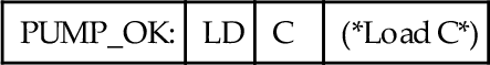
with the instruction earlier in the program to jump to PUMP_OK if a particular condition is realized.
With the IEC 61131-3 operators, an N after the operator is used to negate its value. For example, if we have:
the ANDN operator inverts the value of ladder contacts and ANDs the result.
6.1.1 Ladder Programs and Instruction Lists
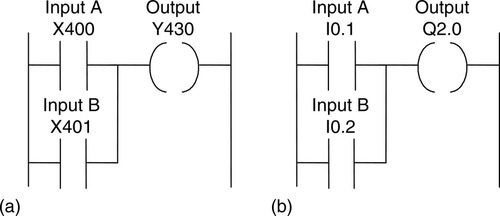
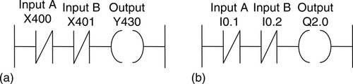
When looked at in terms of ladder diagrams, whenever a rung is started, it must use a “start a rung” code. This might be LD, or perhaps A or L, to indicate that the rung is starting with open contacts, or LDI, or perhaps LDN, LD NOT, AN, or LN, to indicate it is starting with closed contacts. All rungs must end with an output or store result code. This might be OUT or = or ST. The following shows how individual rungs on a ladder are entered using the Mitsubishi mnemonics for the AND gate, shown in Figure 6.1a.

The rung starts with LD because it is starting with open contacts. For Figure 6.1a, since the address of the input is X400, the instruction is LD X400. This is followed by another open contacts input, and so the next program line involves the instruction AND with the address of the element; thus the instruction is AND X401. The rung terminates with an output, so the instruction OUT is used with the address of the output, that is, OUT Y430. The single rung of a ladder would thus be entered as:
For the same rung with Siemens notation (Figure 6.1b), we have:
Consider another example: an OR gate. Figure 6.2a shows the gate with Mitsubishi notation.
The instruction for the rung in Figure 6.2a starts with an open contact and is LD X400. The next item is the parallel OR set of contacts X401. Thus the next instruction is OR X401. The last step is the output, hence OUT Y430. The instruction list would thus be:
Figure 6.2b shows the Siemens version of the OR gate. The following is the Siemens instruction list:
Figure 6.3a shows the ladder system for a NOR gate in Mitsubishi notation.
The rung in Figure 6.3a starts with normally closed contacts, so the instruction is LDI. When added to Mitsubishi instruction, I is used to indicate the inverse of the instruction. The next step is a series of normally closed contacts and so the instruction is ANI, again the I being used to make an AND instruction the inverse. I is also the instruction for a NOT gate. The instructions for the NOR gate rung of the ladder would thus be entered as:
Figure 6.3b shows the NOR gate with Siemens notation. Note that N added to an instruction is used to make the inverse. The instruction list then becomes:
Consider the rung shown in Figure 6.4a in Mitsubishi notation, a NAND gate.
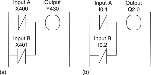
Figure 6.4a starts with the normally closed contacts X400 and so starts with the instruction LDI X400. The next instruction is for a parallel set of normally closed contacts; thus the instruction is ORI X401. The last step is the output, hence OUT Y430. The instruction list is thus:
Figure 6.4b shows the NAND gate in Siemens notation. The instruction list is then:
6.1.2 Branch Codes
The EXCLUSIVE OR (XOR) gate shown in Figure 6.5 has two parallel arms with an AND situation in each arm.
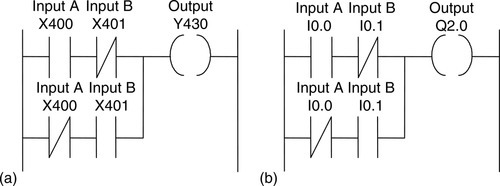
Figure 6.5a shows Mitsubishi notation. With such a situation, Mitsubishi uses an ORB instruction to indicate “OR together parallel branches.” The first instruction is for a normally open pair of contacts X400. The next instruction is for a series set of normally closed contacts X401, hence ANI X401. After reading the first two instructions, the third instruction starts a new line. It is recognized as a new line because it starts with LDI, all new lines starting with LD or LDI. But the first line has not been ended by an output. The PLC thus recognizes that a parallel line is involved for the second line and reads together the listed elements until the ORB instruction is reached. The mnemonic ORB (OR branches/blocks together) indicates to the PLC that it should OR the results of the first and second instructions with that of the new branch with the third and fourth instructions. The list concludes with the output OUT Y430. The instruction list would thus be entered as:
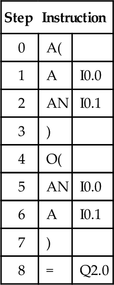
Figure 6.5b shows the Siemens version of an XOR gate. Brackets are used to indicate that certain instructions are to be carried out as a block. They are used in the same way as brackets in any mathematical equation. For example, (2 + 3) / 4 means that the 2 and 3 must be added before dividing by 4. Thus with the Siemens instruction list we have in step 0 the instruction A(. The brackets close in step 3. This means that the A in step 0 is applied only after the instructions in steps 1 and 2 have been applied.
The IEC 61131-3 standard for such programming is to use brackets in the way used in the previous Siemens example, that is, in the same way brackets are used in normal arithmetic. This enables instructions contained within brackets to be deferred until the bracket is completed. Thus the IEC instruction list program:
Gives X + (B × (C + D)).
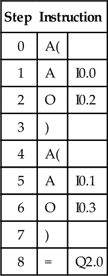
Figure 6.6 shows a circuit that can be considered as two branched AND blocks. Figure 6.6a shows the circuit in Mitsubishi notation. The instruction used here is ANB. The instruction list is thus:
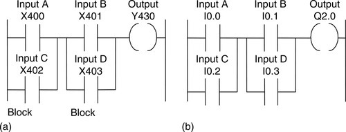
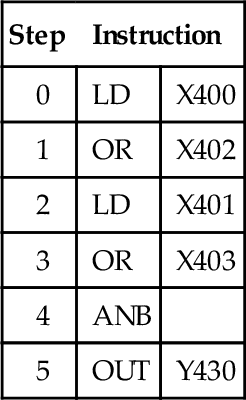
Figure 6.6b shows the same circuit in Siemens notation. Such a program is written as an instruction list using brackets. The A instruction in step 0 applies to the result of steps 1 and 2. The A instruction in step 4 applies to the result of steps 5 and 6. The program instruction list is thus:
6.1.3 More Than One Rung
Figure 6.7a shows a ladder, in Mitsubishi notation, with two rungs. In writing the instruction list we just write the instructions for each line in turn. The instruction LD or LDI indicates to the PLC that a new rung is starting. The instruction list is thus:
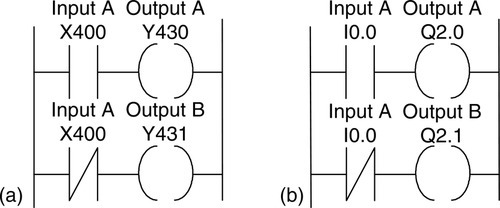
The system is one where when X400 is not activated, there is an output from Y431 but not Y430. When X400 is activated, there is then an output from Y430 but not Y431.
Figure 6.7b shows the same program in Siemens notation. The = instruction indicates the end of a line. The A or AN instruction does not necessarily indicate the beginning of a rung since the same instruction is used for AND and AND NOT. The instruction list is then:
6.1.4 Programming Examples
The following tasks are intended to illustrate the application of the programming techniques given in this section and are the examples for which ladder diagrams and function block diagrams were derived in Section 5.7. (See that section for an explanation of the ladder diagrams; here we show the instruction lists relating to the programs.)
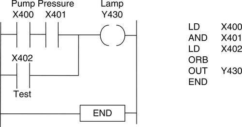
A signal lamp is required to be switched on if a pump is running and the pressure is satisfactory or if the lamp test switch is closed. Figure 6.8 shows the ladder program and the related instruction list.
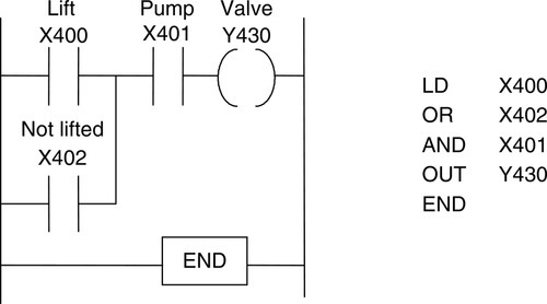
For a valve that is to be operated to lift a load when a pump is running and either the lift switch operated or a switch operated indicating that the load has not already been lifted and is at the bottom of its lift channel, Figure 6.9 shows the ladder program and the related instruction list.
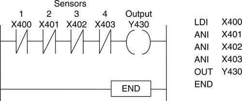
For a system in which there has to be no output when any one of four sensors gives an output and otherwise there is to be an output, Figure 6.10 shows the ladder program and the instruction list.
6.2 Sequential Function Charts
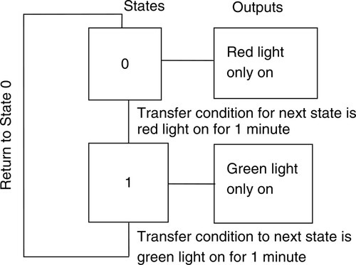
If we wanted to describe a traffic lamp sequence of red-green, one way we could do this would be to represent it as a sequence of functions or states such as red light state and green light state and the inputs and outputs to each state. Figure 6.11 illustrates this. State 0 has an input that is triggered after the green light has been on for 1 minute and an output of red light on, i.e. the transfer condition from the red light is a time of 1 minute. State 1 has an input that is triggered after the red light has been on for 1 minute and an output of green light on, i.e. the transfer condition from the green light is a time of 1 minute. When the green light has been on for 1 minute, there is a transfer back to State 0.
The term sequential function chart (SFC) is used for a pictorial representation of a system’s operation to show the sequence of events involved in its operation and Figure 6.11 is an illustration of the type of operation being described. SFC charts have the following elements:
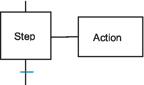
1. The operation is described by a number of separate sequentially connected states or steps that are represented by rectangular boxes, each representing a particular state of the system being controlled and where there is some action performed. The initial start step in a program is represented with double lines, differently from the other steps. Figure 6.12 shows a start step and later steps.
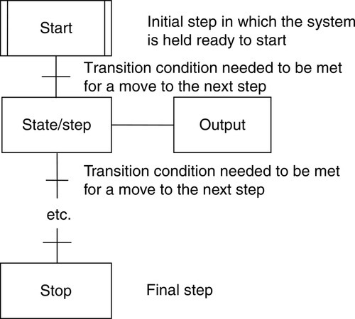
2. Each connecting line between states has a horizontal bar representing the transition condition that has to be realized before the system can move from one state to the next. Two steps can never be directly connected; they must always be separated by a transition. Two transitions can never directly follow from one to another; they must always be separated by a step.
3. The program checks the transition conditions so that when realized the next state following the transition is moved to.
4. The process thus continues from one state to the next until the complete machine cycle is completed.
5. Outputs/actions at any state/step are represented by horizontally linked boxes and occur when that state has been realized. Thus we might have items such as Wait 1 minute or Open valve 1 or Close valve 1.
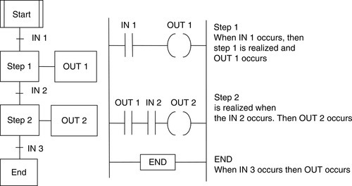
As an illustration, Figure 6.13 shows part of an SFC and its equivalent ladder diagram. The program starts when IN 1 is realized and this gives step 1 output. When this output has completed, the next transition occurs and step 2 occurs with the resulting output 2. When this is completed, the transfer condition occurs that allows for the move to the End step.
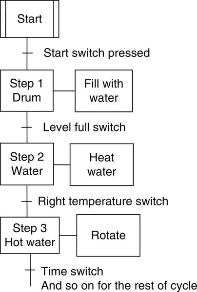
As an illustration of the principles of SFC, consider the situation with, say, part of the washing cycle of a domestic washing machine where the drum is to be filled with water, and then when the drum is full, a heater has to be switched on and remain on until the temperature reaches the required level. Then the drum is to be rotated for a specified time. We have a sequence of states that can be represented in the manner shown in Figure 6.14.
The transition defines the conditions that must occur in order to go to the next step in the program, and so they have to occur between each step in a program. Until the conditions are realized the program continues to execute the current step. Thus we might have for a transition:
Other possibilities are conditions such as:
that have to be realized before progression can occur to the next step in the program. When programming, transitions can be entered using a Boolean expression in structured text (see Chapter 6.3) to check whether a condition is true 1 or false 0. Alternatively a subroutine can be called up to check for the required condition and when realized give a true 1 response, otherwise false 0. At the end of the subroutine an End of Transition (EOT) instruction can then be used to set the state of the transition to the Boolean value realized by the subroutine.
Actions are added to steps to indicate the different functions that the step performs. Thus we might have switching a motor on or perhaps opening a valve or calling up a subroutine.
The Sequential Function Chart language is a powerful graphical technique for describing the sequential behavior of a program. Graphical languages have been used for a number of years, Grafset being a European graphical language. The IEC 61131-1 standard resembles many of the features of Grafset.
6.2.1 Branching and Convergence
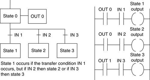
Selective branching is illustrated in Figure 6.15 and allows for different states to be realized, depending on the transfer condition that occurs. Transitions are needed below the horizontal lines in order to indicate the conditions that have to be met to progress from the step above the horizontal line to a step below it.
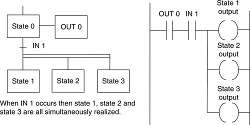
Parallel branching (Figure 6.16), represented by a pair of horizontal lines, allows for two or more different states to be realized and proceed simultaneously. A transition is required outside the pair of horizontal lines in order to indicate the condition that has to be met in order for the group of steps that follow to be simultaneously realized.
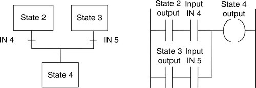
Figures 6.17 and 6.18 show how convergence is represented by an SFC. In Figure 6.17 the sequence can go from state 2 to state 4 if IN 4 occurs or from state 3 to state 4 if IN 5 occurs. The transitions are needed above the horizontal line to indicate the conditions that have to be realized for each of the steps above the line to progress to the step below the line. In Figure 6.18 the sequence can go simultaneously from both state 2 and state 3 to state 4 if IN 4 occurs. The transition is below the pair of horizontal lines and indicates the condition that has to be realized for progression to the step that follows.

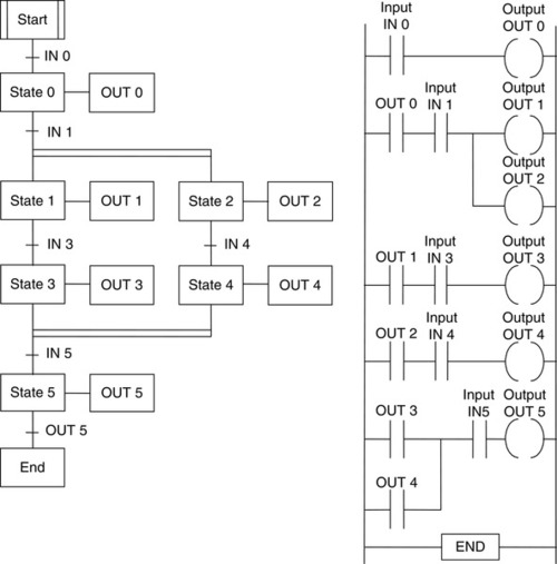
As an illustration of the use of the preceding, Figure 6.19 shows part of a program represented by both its SFC and ladder programs.
6.2.2 Actions
With steps, there is an action or actions that have to be performed. Such actions, such as the outputs in the preceding example, are depicted as rectangular boxes attached to the state (Figure 6.20). The behavior of the action can be given using a ladder diagram, a function block diagram, an instruction list, or structured text. Thus, where a ladder diagram is used, the behavior of the action is shown by the ladder diagram being enclosed within the action box. The action is then activated when there is a power flow into the action box. Figure 6.21a illustrates this concept.
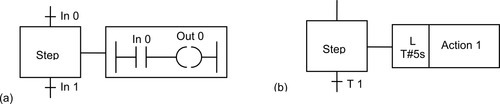
Action boxes can be preceded by qualifiers to specify the conditions to exist for the action. In the absence of a qualifier or the qualifier N, the action is not stored and is executed continually while the associate state is active and stops when it is deactivated. The qualifier P is used for a pulse action that executes only once when a step is activated and is then deactivated. The qualifier D is used for a time-delayed action that only starts after a specified period and stops when the step is deactivated. The qualifier L is used for a time-limited action that starts when the step is activated and terminates after a specified period (Figure 6.21b). Table 6.2 lists the action qualifiers defined in the IEC 61131 standard.
Table 6.2
Action Qualifiers
| Qualifier | Description |
| None | Non-stored, the default, same as N. |
| N | Non-stored, executes while the associated step is active and then stops. |
| R | Resets a stored action. |
| S | Stored. Stays active until a Reset action turns off this action. |
| L | Time limited action. Terminates after a given time. A time period must be specified. |
| D | Time delayed action. Starts after a given time which must be specified. |
| P | A pulse action that occurs once when the step is activated and once when it is deactivated. |
| P1 | A pulse action that only occurs when a step is activated. |
| P0 | A pulse action that only occurs when a step is deactivated. |
| SD | The action starts after a given time, even if the associated step is deactivated before that time has elapsed. |
| DS | The action starts a specific time after the step is activated and the step is still active and stops when the step is deactivated. |
| SL | The action starts when the step is activated and is time limited, executing for a given period. |
When a transition condition is realized and one step is left and the next started, it is necessary to consider what state the action of that step needs to be left in. There may be a need to turn off an activated device that the step had turned on. This can be done in programming the action for that device to carry out such a task. If it is to be returned to its initial state then program it to go to the initial step position.
6.2.3 Programming a PLC
Software is supplied by PLC manufacturers to enable programs to be entered for use by a PLC. As an indication, the following outline is the procedure that would be used with Allen-Bradley software to program a sequential function chart. With the SFC toolbar on the screen, the button for the item wanted is clicked and then dragged to the required location on the SFC chart. Thus the element for a step followed by a transition might be so dragged. To connect two elements, for example two steps, together, a pin on one of the elements is clicked and then the pin on the other element is clicked. A valid connection point is shown by a green dot appearing. A simultaneous button on the toolbar can be clicked and dragged to add a simultaneous branch to the program, likewise a selection branch. To program a transition, the text area of the transition icon is double clicked and if a Boolean expression is required it is just typed in. To call a subroutine, the transition icon is right clicked, Set JSR selected and then the routine selected, then OK clicked. To add an action to a step, the step is right clicked and Add Action selected. The button in the action element is clicked to a series of tabs which are used to specify the qualifier for the action, e.g. L for a time qualifier, the action order and a tag. The text entry of the action element is right clicked and Set JSR selected for subroutines to be added.
6.3 Structured Text
Structured text is a programming language that strongly resembles the programming language Pascal. Programs are written as a series of statements separated by semicolons. The statements use predefined statements and subroutines to change variables, these being defined values, internally stored values, or inputs and outputs.
Assignment statements are used to indicate how the value of a variable is to be changed, for example

is used to indicate that a light, the variable, is to have its “value” changed, that is, switched on or off, when switch A changes its “value,” that is, is on or off. The general format of an assignment statement is:

where Y represents an expression that produces a new value for the variable X and := is the assignment symbol. The variable retains the assigned value until another assignment changes the value. Other examples are:

to indicate that the light is switched on by either switch A OR switch B. Using the AND function, we might have:

to indicate that start occurs when steam AND the pump are on.
Table 6.3 shows some of the operators, such as the OR and AND in the preceding statements, that are used in structured text programs and their relative precedence when an expression is being evaluated. Parentheses (brackets) are used to group expressions within expressions to ensure that the expression is executed in the required sequence. For example:
Table 6.3
Structured Text Operators
| Operator | Description | Precedence |
| (…) | Parenthesized (bracketed) expression | Highest |
| Function(…) | List of parameters of a function | |
| ** | Raising to a power | |
| -, NOT | Negation, Boolean NOT | |
| *, /, MOD | Multiplication, division, modulus operation | |
| +, - | Addition, subtraction | |
| <, >, <=, >= | Less than, greater than, less than or equal to, greater than or equal to | |
| =, <> | Equality, inequality | |
| AND, & | Boolean AND | |
| XOR | Boolean XOR | |
| OR | Boolean OR | Lowest |
InputA := 6;
InputB := 4;
InputC := 2;
OutputQ := InputA/3 + InputB/(3 - InputC);
has (3 – InputC) evaluated before its value is used as a divisor, so the second part of the OutputQ statement is 4/(3 – 2) = 4. Division has precedence over addition, so the first part of the statement is evaluated before the addition, that is, 6/3. So we have for OutputQ the value 2 + 4 = 6.
Structured text is not case sensitive; thus lowercase or capital letters can be used as is felt necessary to aid clarity. Likewise, spaces are not necessary but can be used to aid clarity; likewise indenting lines. All the identities of directly represented variables start with the % character and are followed by a one- or two-letter code to identify whether the memory location is associated with inputs, outputs, or internal memory and whether it is bits, bytes, or words, such as
%IX100 (*Input memory bit 100*)
%ID200 (*Input memory word 200*)
%QX100 (*Output memory bit 100*)
The first letter is I for input memory location, Q for output memory location, or M for internal memory. The second letter is X for bit, B for byte (8 bit), W for word (16 bits), D for double word (32 bits), or L for long word (64 bits).
AT is used to fix the memory location for a variable. Thus we might have:
Input1 AT %IX100; (*Input1 is located at input memory bit 100*)
6.3.1 Conditional Statements
The IF statement:
is used to indicate that if the fluid temp variable is ON, that is, 1, the actions following that line in the program are to occur. The IF statement:
is used to indicate that if the fluid temp variable is NOT 1, the actions following that line in the program are to occur. The IF statement:
IF fluid_temp1 OR fluid_temp2 THEN
is used to indicate that if the fluid temp variable 1, the fluid temp variable 2 is ON, that is, 1, the actions following that line in the program are to occur.
IF … THEN … ELSE is used when selected statements are to be executed when certain conditions occur. For example:
IF (Limit_switch1 AND Workpiece:Present) THEN
 Gate1 := Open;
 Gate2 := Close;
ELSE
 Gate1 := Close;
 Gate2 := Open;
END_IF;
Note that the end of the IF statement has to be indicated. Another example, using PLC addresses, is:
IF (I:000/00 = 1) THEN
 O:001/00 := 1;
ELSE
 O:000/01 := 0;
END_IF;
So, if there is an input to I:000/00 to make it 1, output O:001/00 is 1; otherwise it’s 0.
CASE is used to give the condition that selected statements are to be executed if a particular integer value occurs else some other selected statements. For example, for temperature control we might have:
CASE (Temperature) OF
 0 … 40 : Furnace:switch := On;
 40 … 100: Furnace:switch := Off;
ELSE
 Furnace:switch := Off;
END_CASE;
Note, as with all conditional statements, the end of the CASE statement has to be indicated. Another example might be, for the operation of a motor with fans being required to operate at different speeds based on the operation of particular switch positions:
CASE speed_setting OF
 1: speed := 5;
 2: speed := 10;
 3: speed := 15; fan 1 := ON;
 4: speed := 20; fan 2 := ON;
ELSE
 Speed :=0; speed fault := TRUE;
END_CASE
6.3.2 Iteration Statements
These are used where it is necessary to repeat one or more statements a number of times, depending on the state of some variable. The FOR … DO iteration statement allows a set of statements to be repeated depending on the value of the iteration integer variable. For example:
FOR Input := 10 to 0 BY −1
 DO
 Output := Input;
END_FOR;
has the output decreasing by 1 each time the input, dropping from 10 to 0, decreasing by 1.
WHILE … DO allows one or more statements to be executed while a particular Boolean expression remains true, such as:
OutputQ := 0;
WHILE InputA AND InputB
 DO
 OutputQ =: OutputQ + 1;
END_WHILE;
REPEAT … UNTIL allows one or more statements to be executed and repeated while a particular Boolean expression remains true.
OutputQ := 0
REPEAT
 OutputQ := OutputQ + 1;
UNTIL (Input1 = Off) OR (OutputQ > 5)
END_REPEAT;
6.3.3 Structured Text Programs
Programs have first to define the data types required to represent data, such as:
TYPE Motor: (Stopped, Running);
END_TYPE;
TYPE Valve: (Open, shut);
END_TYPE;
TYPE Pressure: REAL; (*The pressure is an analogue value*)
END_TYPE;
the variables, that is, signals from sensors and output signals to be used in a program, such as:
VAR_IN (*Inputs*)
 PumpFault : BOOL; (*Pump operating fault is a Boolean variable*)
END_VAR;
VAR_OUT (*Outputs*)
 Motor_speed : REAL;
END_VAR;
VAR_IN
 Value: INT; (*The value is an integer*)
END_VAR;
 VAR
 Input1 AT %IX100; (*Input1 is located at input memory bit 100*)
END_VAR;
and any initial values to be given to variables, such as:
VAR
 Temp : REAL =100; (*Initial value is an analogue number 100*)
END_VAR;
before getting down to the instruction statements.
The following is an example of a function block that might appear in a larger program and is concerned with testing voltages:
FUNCTION_BLOCK TEST_VOLTAGE
 VAR_INPUT
 VOLTS1, VOLTS2, VOLTS3
 END_VAR
 VAR_OUTPUT
 OVERVOLTS : BOOL;
 END_VAR
 IF VOLTS1 > 12 THEN
 OVERVOLTS :=TRUE; RETURN;
 END_IF;
 IF VOLTS2 > 12 THEN
 OVERVOLTS :=TRUE; RETURN;
 END_IF;
 IF VOLTS3 > 12 THEN
 OVERVOLTS :=TRUE;
 END_IF;
END_FUNCTION_BLOCK;
If the testing of volts 1, volts 2, or volts 3 indicates that any one of them is more than 12, the output OVERVOLTS is set to true and the RETURN statement called to terminate the execution of the function block. In the rest of the program, when OVERVOLTS is set to true, the program will initiate some action.
6.3.4 Comparison with Ladder Programs
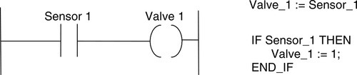
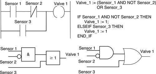
Figure 6.22 shows a ladder rung and its equivalent expressions in structured text; Figure 6.23 shows another ladder rung and equivalents in function box and STC.
Summary
A programming method that can be considered to be the entering of a ladder program using text is the instruction list (IL). An IL gives programs as a series of instructions, each instruction being on a new line. Each instruction consists of an operator followed by one or more operands, that is, the subjects of the operator. Mnemonic codes are used, each code corresponding to an operator/ladder element.
The sequential function chart (SFC) programming method is used for a pictorial representation of a system’s operation to show the sequence of the events involved in its operation. The operation is described by a number of separate sequentially connected states or steps that are represented by rectangular boxes, each representing a particular state of the system being controlled. Each connecting line between states has a horizontal bar representing the transition condition that has to be realized before the system can move from one state to the next. When the transfer conditions to the next state are realized, the next state or step in the program occurs. The process thus continues from one state to the next until the entire machine cycle is completed. Outputs/actions at any state are represented by horizontally linked boxes and occur when that state has been realized.
With the structured text (ST) programming method, programs are written as a series of statements separated by semicolons. The statements use predefined statements and subroutines to change variables, these being defined values, internally stored values, or inputs and outputs. Assignment statements are used to indicate how the value of a variable is be changed, such as X := Y. Structured text is not case sensitive and spaces are not necessary but can be used to aid clarity. IF … THEN … ELSE is used when selected statements are to be executed when certain conditions occur. CASE is used to give the condition that selected statements are to be executed if a particular integer value occurs else some other selected statements. FOR … DO … allows a set of statements to be repeated depending on the value of the iteration integer variable. WHILE … DO .. allows one or more statements to be executed while a particular Boolean expression remains true. REPEAT … UNTIL … allows one or more statements to be executed and repeated while a particular Boolean expression remains true.
Problems
Problems 1 through 24 have four answer options: A, B, C, or D. Choose the correct answer from the answer options.
1. Decide whether each of these statements is true (T) or false (F). The instruction list:
describes a ladder diagram rung for which there is an output when:
(i) Input X401 is activated but X402 is not.
(ii) Input X401 and input X402 are both activated.
A. (i) T (ii) T
B. (i) T (ii) F
C. (i) F (ii) T
D. (i) F (ii) F
2. Decide whether each of these statements is true (T) or false (F). The instruction list:
describes a ladder diagram rung for which there is an output when:
(i) Input X401 is activated but X402 is not.
(ii) Input X402 is activated but X401 is not.
A. (i) T (ii) T
B. (i) T (ii) F
C. (i) F (ii) T
D. (i) F (ii) F
3. Decide whether each of these statements is true (T) or false (F). The instruction list:
describes a ladder diagram rung for which there is an output when:
(i) Input X401 is activated but X402 is not.
(ii) Input X401 and input X402 are both activated.
A. (i) T (ii) T
B. (i) T (ii) F
C. (i) F (ii) T
D. (i) F (ii) F
4. Decide whether each of these statements is true (T) or false (F). The instruction list:
describes a ladder diagram rung for which there is an output when:
(i) Input X401 is activated but X402 is not.
(ii) Input X401 and input X402 are both activated.
A. (i) T (ii) T
B. (i) T (ii) F
C (i) F (ii) T
D. (i) F (ii) F
5. Decide whether each of these statements is true (T) or false (F). The instruction list:
describes a ladder diagram rung for which there is:
(i) An output when input X401 is momentarily activated.
(ii) No output when X402 is activated.
A. (i) T (ii) T
B. (i) T (ii) F
C. (i) F (ii) T
D. (i) F (ii) F
6. Decide whether each of these statements is true (T) or false (F). The instruction list:
describes a ladder diagram rung for which there is an output when:
(i) Input I0.1 is activated but I0.2 is not.
(ii) Input I0.1 and input I0.2 are both activated.
A. (i) T (ii) T
B. (i) T (ii) F
C. (i) F (ii) T
D. (i) F (ii) F
7. Decide whether each of these statements is true (T) or false (F). The instruction list:
describes a ladder diagram rung for which there is an output when:
(i) Input I0.1 is activated but I0.2 is not.
(ii) Input I0.2 is activated but I0.1 is not.
A. (i) T (ii) T
B. (i) T (ii) F
C. (i) F (ii) T
D. (i) F (ii) F
8. Decide whether each of these statements is true (T) or false (F). The instruction list:
describes a ladder diagram rung for which there is an output when:
(i) Input I0.1 is activated but I0.2 is not.
(ii) Input I0.1 and input I0.2 are both activated.
A. (i) T (ii) T
B. (i) T (ii) F
C. (i) F (ii) T
D. (i) F (ii) F
9. Decide whether each of these statements is true (T) or false (F). The instruction list:
describes a ladder diagram rung for which there is an output when:
(i) Input I0.1 is activated but I0.2 is not.
(ii) Input I0.1 and input I0.2 are both activated.
A. (i) T (ii) T
B. (i) T (ii) F
C. (i) F (ii) T
D. (i) F (ii) F
10. Decide whether each of these statements is true (T) or false (F). The instruction list:
describes a ladder diagram rung for which there is:
(i) An output when input I0.1 is momentarily activated.
(ii) No output when I0.2 is activated.
A. (i) T (ii) T
B. (i) T (ii) F
C. (i) F (ii) T
D. (i) F (ii) F
11. Decide whether each of these statements is true (T) or false (F). The instruction list:
describes a program for which:
(i) When X401 is activated, there is an output from Y430 but not Y431.
(ii) When X401 is not activated, there is an output from Y431 but not Y430.
A. (i) T (ii) T
B. (i) T (ii) F
C. (i) F (ii) T
D. (i) F (ii) F
12. Decide whether each of these statements is true (T) or false (F). The instruction list:
describes a program for which there will be an output from Y431 when:
(i) Just X400 or X401 or X402 is activated.
(ii) Just X400 and X403 are activated.
A. (i) T (ii) T
B. (i) T (ii) F
C. (i) F (ii) T
D. (i) F (ii) F
13. Decide whether each of these statements is true (T) or false (F). The instruction list:
describes a program for which there will be an output from Y430 when:
(i) Just X400 or X402 is activated.
(ii) Just X400 and X401 are activated.
A. (i) T (ii) T
B. (i) T (ii) F
C. (i) F (ii) T
D. (i) F (ii) F
14. Decide whether each of these statements is true (T) or false (F). For the sequential function chart shown in Figure 6.24:
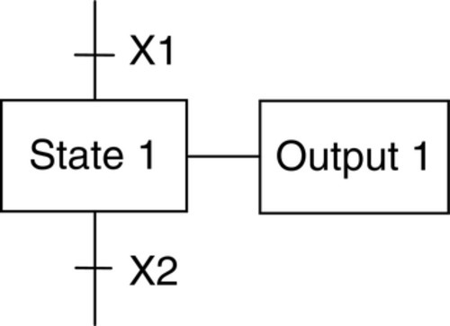
(i) State 1 is realized when condition X1 is realized.
(ii) Output 1 occurs when condition X2 is realized.
A. (i) T (ii) T
B. (i) T (ii) F
C. (i) F (ii) T
D. (i) F (ii) F
15. Decide whether each of these statements is true (T) or false (F).
For the sequential function chart shown in Figure 6.25, if State 1 is active:
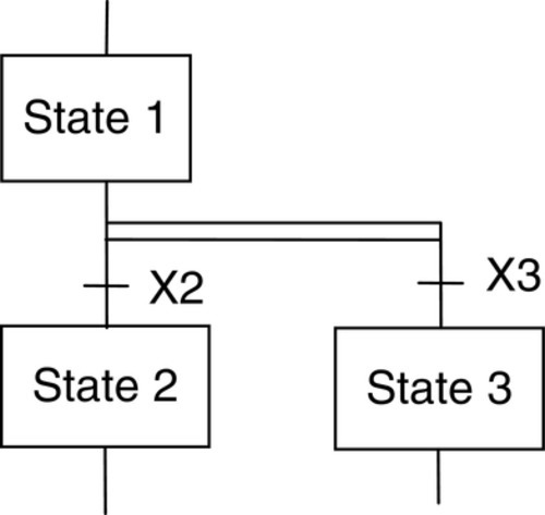
(i) State 2 is realized when condition X2 is realized.
(ii) State 3 occurs when condition X3 is realized.
A. (i) T (ii) T
B. (i) T (ii) F
C. (i) F (ii) T
D. (i) F (ii) F
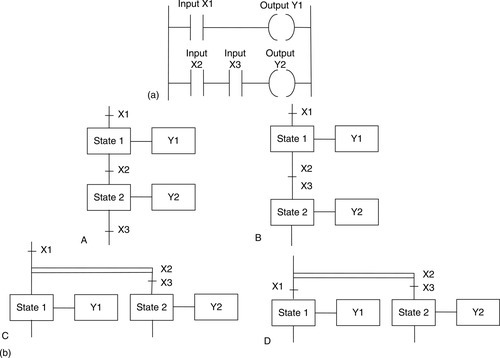
16. For the ladder program described in Figure 6.26a, which of the sequential function charts in Figure 6.26b will represent it?
Problems 17, 18, and 19 concern the sequential function chart shown in Figure 6.27.
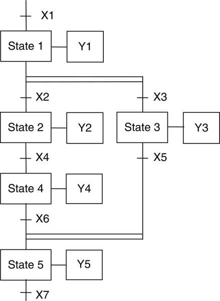
17. Decide whether each of these statements is true (T) or false (F). For the sequential function chart shown in Figure 6.27, output Y2 will occur if output Y1 has been realized and:
(i) Both X2 and X3 have been realized.
(ii) Just X2 has been realized.
A. (i) T (ii) T
B. (i) T (ii) F
C. (i) F (ii) T
D. (i) F (ii) F
18. Decide whether each of these statements is true (T) or false (F). For the sequential function chart shown in Figure 6.27, output Y4 will occur if output Y2 has occurred and:
(ii) X4 has been realized.
A. (i) T (ii) T
B. (i) T (ii) F
C. (i) F (ii) T
D. (i) F (ii) F
19. Decide whether each of these statements is true (T) or false (F). For the sequential function chart shown in Figure 6.27, output Y5 will occur if:
(i) Output Y4 has occurred and condition X6 is realized.
(ii) Output Y3 has occurred and condition X5 is realized.
A. (i) T (ii) T
B. (i) T (ii) F
C. (i) F (ii) T
D. (i) F (ii) F
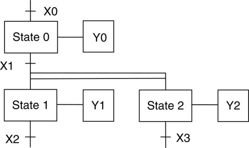
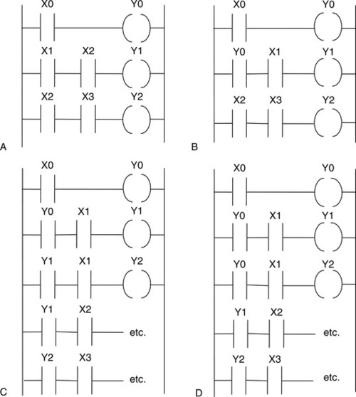
20. For the sequential function chart in Figure 6.28, which of the ladder programs in Figure 6.29 describes the same program?
21. Decide whether each of these statements is true (T) or false (F). For the following structured text program element:
VAR
 i: INT;
END_VAR;
i :- 0;
REPEAT
 i :- i + 1;
UNTIL i:= 5;
END_REPEAT;
(i) The variable i can only have the 0 or 1 values.
(ii) Each time the program repeats, i has its value increased by 1.
A. (i) T (ii) T
B. (i) T (ii) F
C. (i) F (ii) T
D. (i) F (ii) F
22. Decide whether each of these statements is true (T) or false (F). For the following structured text program element:
IF Input1 THEN
 Motor:=- 1;
END_IF;
IF Input2 THEN
 Motor:= 0;
END_IF;
(i) When input 1 occurs, the motor is switched on.
(ii) When input 2 occurs, the motor is switched off.
A. (i) T (ii) T
B. (i) T (ii) F
C. (i) F (ii) T
D. (i) F (ii) F
23. Decide whether each of these statements is true (T) or false (F). For the following structured text program element:
IF (Limit_switch_1 AND Workpiece:Present) THEN
 Gate_1 :- Open;
 Gate_2 :- Closed;
ELSE
 Gate_1 :- Closed;
 Gate_2 :- Open;
END_IF;
(i) If only the workpiece is present, gate 1 is open and gate 2 is closed.
(ii) If only the limit switch is activated, gate 1 is closed and gate 2 is open.
A. (i) T (ii) T
B. (i) T (ii) F
C. (i) F (ii) T
D. (i) F (ii) F
24. Decide whether each of these statements is true (T) or false (F). For the following structured text program element:
VAR
 Start_Up AT %IX120;
END_VAR
(i) Start_Up can be found at input memory location bit 120.
(ii) Start_Up has the value 120 bits.
A. (i) T (ii) T
B. (i) T (ii) F
C. (i) F (ii) T
D. (i) F (ii) F
25. Write a sequential function chart program for following the operation of a start switch, after which a tank is filled by opening valve 1 until a level switch 1 is triggered, then the tank is drained by opening drain valve 2 until level switch 2 is triggered, then the sequence is repeated.
26. Write a structured text program for the following: a tank is filled by opening valve 1, as long as level switch 1 is not triggered and the drain valve is closed.
27. Write a structured text program to set the temperature of an enclosure by switches to the values 40, 50, 60, and 70, and switch on fan 1 when the temperature is 60 and fan 2 when it is 70.