Designing Systems
This chapter considers the way programs are designed and how they and a PLC system can be tested and faults found. This involves consideration of both the hardware and the software.
13.1 Program Development
Whatever the language in which a program is to be written, a systematic approach to the problem can improve the chance of high-quality programs being generated in as short a time as possible. A systematic design technique is likely to involve the following steps:
1 A definition of what is required, with the inputs and outputs specified.
2. A definition of the algorithm to be used. An algorithm is a step-by-step sequence that defines a method of solving the problem. This can often be shown by a flowchart or can be written in pseudocode, which involves the use of the words BEGIN, DO, END, IF-THEN-ELSE, and WHILE-DO.
3. The algorithm is then translated into instructions that can be input to the PLC. Because programs are often very long and can end up difficult to write as a long single block and are even more difficult to later follow for fault finding and maintenance, it is advisable to break the program down into areas that are then further subdivided until manageably sized blocks of program occur. This technique is termed top-down design.
4. The program is then tested and debugged.
5. The program is documented so that any person using or having to modify the program at a later date understands how the program works.
13.1.1 Flowcharts and Pseudocode
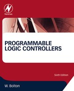
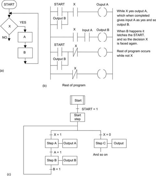
Figure 13.1a shows the symbols used in flowcharts. Each step of an algorithm is represented by one or more of these symbols and linked by lines to represent the program flow (Figure 13.1b). Pseudocode is a way of describing the steps in an algorithm in an informal way.
Consider how the following program operations can be represented by flowcharts and pseudocode and then programmed using ladder and sequential function chart programming:
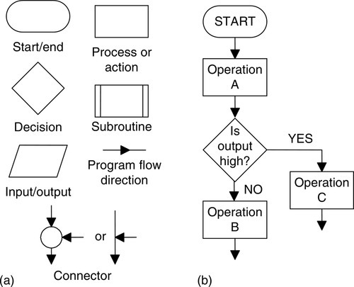
• Sequential. Consider a sequence in which event A has to be followed by event B. Figure 13.2a shows how this can be represented by a flowchart. In pseudocode this is written as:
BEGIN A
 DO A
END A
BEGIN B
 DO B
END B
A sequence can be translated into a ladder program in the way shown in Figure 13.2b. When the start input occurs, output A happens. When action A happens, it operates the output A relay and results in output B occurring. Figure 13.2c shows the sequential function chart representation of a sequence.
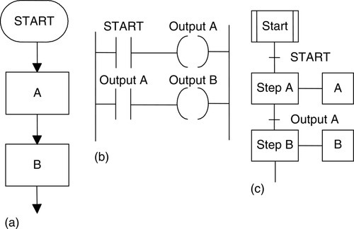
• Conditional. Figure 13.3a shows the flowchart for when A or B is to happen if a particular condition X being YES or NO occurs. The pseudocode to describe this situation involves the words IF-THEN-ELSE-ENDIF.
IF X
THEN
 BEGIN A
 DO A
 END A
ELSE
 BEGIN B
 DO B
 END B
ENDIF X
Such a condition can be represented by the ladder diagram shown in Figure 13.3b. When the start input occurs, the output will be A if there is an input to X; otherwise the output is B. Figure 13.3c shows the sequential function chart for such selective branching.
• Looping. A loop is a repetition of some element of a program that is repeated as long as some condition prevails. Figure 13.4a shows how this repetition can be represented by a flowchart. As long as condition X is realized, sequence A followed by B occurs and is repeated. When X is no longer realized, the program continues and the looping through A and B ceases. In pseudocode, this can be represented using the words WHILE-DO-ENDWHILE:
WHILE X
 BEGIN A
 DO A
 END A
 BEGIN B
 DO B
 END B
ENDWHILE X
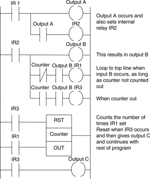
Figure 13.4b shows how this idea can be represented by a ladder diagram with an internal relay. Figure 13.4c shows the sequential flowchart.
Where a loop has to be repeated a particular number of times, a counter can be used, receiving an input pulse each time a loop occurs and switching out of the loop sequence when the required number of loops has been completed (Figure 13.5).
13.2 Safe Systems
Modern safety legislation charges employers with duties that include making the workplace safe and free of risks to health, ensuring that plant and machinery are safe and that safe systems of work are established and followed. There is thus a need to assess the risks in the workplace. This means looking for hazards, that is, anything that can cause harm, deciding who might be harmed and how, evaluating the risks that somebody will be harmed by a hazard and whether existing precautions are adequate or whether more needs to be done to reduce the chance of harm occurring, recording the findings, and reviewing and revising the assessment, if necessary.
Thus, for example, issues such as emergency stops and access doors on equipment need to be considered, the risks assessed, and safe systems then designed. With regard to access doors on equipment, switch contacts can be used on such doors so that the system is stopped if the doors are not correctly guarding equipment.
An important standard is IEC 61508: Functional Safety of Electrical/Electronic/Programmable Electronic Safety-Related Systems. The standard is in seven parts, as follows: Part 1: General requirements; Part 2: Requirements for E/E/PE safety-related systems; Part 3: Software requirements; Part 4: Definitions and abbreviations; Part 5: Examples of methods for the determination of safety integrity levels; Part 6: Guidelines on the application of IEC 61508-2 and IEC 61508-3; and Part 7: Overview of techniques and measures. To provide functional safety of a machine or plant, the safety-related protective or control system must function correctly, and when a failure occurs it must operate so that the plant or machine is brought into a safe shutdown state.
13.2.1 PLC Systems and Safety
Safety must be a priority in the design of a PLC system. Thus, emergency stop buttons and safety guard switches must be hardwired and not depend on the PLC software for implementation, so that, in a situation where there is a failure of the stop switch or PLC, the system is automatically safe. The system must be fail-safe. Thus if failure occurs, the outputs must revert to a fail-safe mode so that no harm can come to anyone. For example, the guards on a machine must not be open or be capable of being opened if the PLC fails.
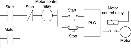
With a PLC system, a stop signal can be provided by a switch as shown in Figure 13.6. This arrangement is unsafe as an emergency stop because if there is a fault and the switch cannot be operated, then no stop signal can be provided. Thus to start we momentarily close the push-button start switch and the motor control internal relay then latches this closure and the output remains on. To stop we have to momentarily open the stop switch; this unlatches the start switch. However, if the stop switch cannot be operated, we cannot stop the system. What we require is a system that will still stop if a failure occurs in the stop switch.
We can achieve this by the arrangement shown in Figure 13.7. The program has the stop switch as open contacts. However, because the hardwired stop switch has normally closed contacts, the program has the signal to close the program contacts. Pressing the stop switch opens the program contacts and stops the system.

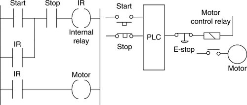
For a safe emergency stop system, we need one that will provide a stop signal if there is a fault and the switch cannot be operated. Because there might be problems with a PLC, we also need the emergency stop to operate independently of the PLC. Putting the emergency stop in the input to the PLC gives an unsafe system (Figure 13.8).

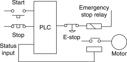
Figure 13.9 shows a safer system where the emergency stop switch is hardwired in the output. Pressing the emergency stop button switch stops, say, a running motor. When we release the stop button, the motor will not restart again, because the internal relay contacts have come unlatched.
13.2.2 Emergency Stop Relays
Emergency stop relays are widely used for emergency stop arrangements, such as the PNOZ p1p from Pilz GmbH & Co. This device has LEDs for indicating the status of input and output circuits, the reset circuit and power supply, and faults. However, the base unit can be connected via an interface module so that its status can be read by a PLC. This interface isolates the output from the emergency stop relay from the signal conditioning and input to the PLC by means of optoisolators (refer back to Figure 1.8). Thus, though the emergency stop operates independently of the PLC, it can provide signals that a PLC can use to, say, initiate safe closing-down procedures. Figure 13.10 illustrates this idea.
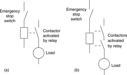
A simple emergency stop relay in which operation of the emergency stop button breaks the control circuit to the relay, causing it to deenergize and switch off the power (Figure 13.11a), has the problem that if the relay contacts weld together, the emergency stop will not operate. This can be overcome using a dual-channel mode of operation in which there are two normally closed contacts in series and both are broken by the action of the relay deenergizing (Figure 13.11b). Safety can be increased yet further if three contacts in series are used, one using normally closed contacts and the others normally open contacts. Then one set of contacts has to be deenergized and the other two energized.
13.2.3 Safety Functions
In designing control systems, it is essential that personnel are prevented from coming into contact with machinery while it is active. This might involve:
• Two-handed engaging so that both hands must be on switches all the time and the machine will switch off if only one of the switches is being engaged.
• Protective door monitoring to prevent access to a machine while it is operating. This can be achieved by the use of safety interlocks such as doors and gates. Limit switches positioned on door and gate latches can be used so that when the door or gate is unlatched, the limit switch is opened and closes down the machinery. However, it is relatively simple for operatives to defeat such limit switches by sticking a device such as a screwdriver in the contacts to force a machine to operate. More sophisticated safety interlocks have thus been devised, such as proximity switches and key locks.
• Light curtains to prevent any person getting close to machinery. A danger zone, such as a packaging machine, can use infrared beams to protect people from getting too close. If a light beam is broken, it immediately triggers a safe shutdown command.
• Safety mats are another way of detecting when someone is too close to a machine. They are placed round a machine and when someone steps on the mat, a contact is closed, causing the machine to stop.
• Emergency stop relays, to enable machinery to be stopped in the event of an emergency (see Section 13.2.2).
Thus a safe-operating system for a work cell might use gated entry systems, such as guards on machines that activate stop relays if they are not in place, light curtains, and emergency stop relays.
13.2.4 Safety PLCs
Safety PLCs are specially designed to enable safety functions to be realized. In a safety PLC there can be two or three microprocessors that perform exactly the same logic, check against each other, and give outputs only if there is agreement. One method that is used is a two-channel system with two identical subsystems that communicate with each other via a fiber-optic cable link. The inputs from the sensors are fed simultaneously to both subsystems. During operation, data is passed between the two subsystems via the fiber-optic cable. They operate in synchronism with the same program and compare input and output signals, the results of logic operations, counters, and the like, and automatically go into a safe-stop condition if there are different outputs or internal faults or failures. For safety-related digital outputs, actuators are switched on or off from both subsystems. This means that one subsystem alone can shut down equipment.
13.3 Commissioning
Commissioning of a PLC system involves:
1. Checking that all the cable connections between the PLC and the plant being controlled are complete, safe, to the required specification, and meet local standards.
2. Checking that the incoming power supply matches the voltage setting for which the PLC is set.
3. Checking that all protective devices are set to their appropriate trip settings.
4. Checking that emergency stop buttons work.
5. Checking that all input/output devices are connected to the correct input/output points and giving the correct signals.
6. Loading and testing the software.
13.3.1 Testing Inputs and Outputs
Input devices, such as switches, can be manipulated to give the open and closed contact conditions and the corresponding LED on the input module observed. It should be illuminated when the input is closed and not illuminated when it is open. Failure of an LED to illuminate could be because the input device is not correctly operating, there are incorrect wiring connections to the input module, the input device is not correctly powered, or the LED or input module is defective. For output devices that can be safely started, push buttons might have been installed so that each output could be tested.
Another method that can be used to test inputs and outputs is forcing. This involves software, rather than mechanical switching on or off, being used with instructions from the display on the screen being used to turn off or on inputs/outputs. Forcing thus overwrites an input or output condition. This permits the operation of inputs and outputs to be tested, also whether the inputs and outputs are correctly wired to the PLC.
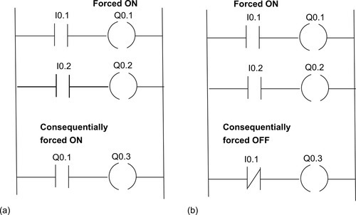
For example, with the Siemens S7-1200 system, under the Watch and Force menu, the Force Table entry is clicked and then the address of the item being forced is entered and then the Force value of TRUE or FALSE. With the Mitsubishi FX PLC keys are pressed to select the Forced I/O facility and within the resulting Set/Reset window the Input/Output address to be forced is entered and the value of on or off entered. Thus an output or an input is forced to the selected forced value and the consequences of that action observed. Figure 13.12(a) illustrates this when an output Q0.1 is forced on. As a consequence output Q0.3 is switched on. Figure 13.12(b) shows the effects of an input I0.1 being forced on. Forcing can only be stopped by clicking the Stop Forcing icon or using a stop forcing instruction. Figure 13.13 shows how forcing can be used with a sequential function chart program. A transition can be forced and will override the conditions of the transition each time the program reaches that transition. If a transition is forced in a simultaneous branch to be false (Figure 13.13(a)) the program stays in that branch as long as the forcing is active, being prevented from reaching the last step of that branch. Another forcing option is to force a simultaneous path (Figure 13.13(b)). This prevents the execution of a path and thus one or more paths of a simultaneous branch. Great care and precautions must be taken during the use of forcing because arbitrary inputs and outputs are being assigned to the process. As a consequence it can damage machinery or harm people also when forcing is removed items may still be left in the forced state.

13.3.2 Testing Software
Most PLCs contain some software-checking program. This checks through the installed program for incorrect device addresses and provides a list on a screen or as a printout of all the input/output points used, counter and timer settings, and so on, with any errors detected. For example, there might be a message that an output address is being used more than once in a program, a timer or counter is being used without a preset value, a counter is being used without a reset, or the like.
13.3.3 Simulation
Many PLCs are fitted with a simulation unit that reads and writes information directly into the input/output memory and so simulates the actions of the inputs and outputs. The installed program can thus be run and inputs and outputs simulated so that they, and all preset values, can be checked. To carry out this type of operation, the terminal has to be placed in the correct mode. For Mitsubishi this is termed the monitor mode, for Siemens the test mode, and for Telemecanique the debug mode.
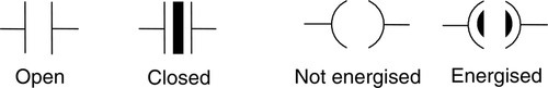
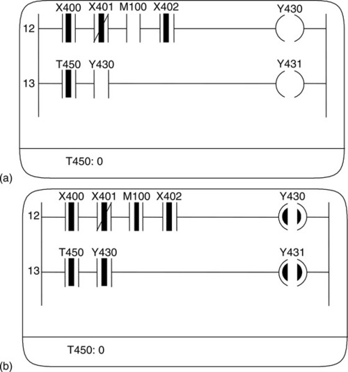
With a Mitsubishi in monitor mode, Figure 13.14 shows how inputs appear when open and closed and how output looks when not energized and energized. The display shows a selected part of the ladder program and what happens as the program proceeds. Thus at some stage in a program the screen might appear in the form shown in Figure 13.15a. For rung 12, with inputs to X400, X401, and X402 but not M100, there is no output from Y430. For rung 13, the timer T450 contacts are closed, the display at the bottom of the screen indicating that there is no time left to run on T450. Because Y430 is not energized, the Y430 contacts are open, so there is no output from Y431. If we now force an input to M100, the screen display changes to that shown in Figure 13.5b. Now Y430, and consequently Y431, come on.
13.4 Fault Finding
With any PLC-controlled plant, by far the greater percentage of faults are likely to be with sensors, actuators, and wiring rather than within the PLC itself. Of the faults within the PLC, most are likely to be in the input/output channels or power supply rather than in the CPU.
As an illustration of a fault, consider a single output device failing to turn on, even though the output LED is on. If testing of the PLC output voltage indicates that it is normal, the fault might be a wiring fault or a device fault. If checking of the voltage at the device indicates the voltage there is normal, the fault is the device. As another illustration, consider all the inputs failing. This might be as a result of a short circuit or earth fault with an input. A possible procedure to isolate the fault is to disconnect the inputs one by one until the faulty input is isolated. An example of another fault is if the entire system stops. This might be a result of a power failure, someone switching off the power supply, or a circuit breaker tripping.
Many PLCs provide built-in fault analysis procedures that carry out self-testing and display fault codes, possibly with a brief message that can be translated by looking up the code in a list, which gives the source of the fault and possible methods of recovery. For example, the fault code may indicate that the source of the fault is in a particular module, with the method of recovery given as “Replace that module” or, perhaps, “Switch the power off and then on.”
13.4.1 Fault Detection Techniques
The following are some common fault detection techniques:
• Timing checks. The term watchdog is used for a timing check that is carried out by the PLC to check that some function has been carried out within the normal time. If the function is not carried out within the normal time, a fault is assumed to have occurred and the watchdog timer trips, setting off an alarm and perhaps closing down the PLC. As part of the internal diagnostics of PLCs, watchdog timers are used to detect faults. The watchdog timer is preset to a time slightly longer than the scan time would normally be. It is then set at the beginning of each program scan and, if the cycle time is normal, it does not time out and is reset at the end of a cycle, ready for the next cycle. However, if the cycle time is longer than it would normally be, the watchdog timer times out and indicates that the system has a fault.
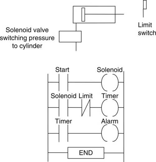
Within a program, additional ladder rungs are often included so that when a function starts, a timer is started. If the function is completed before the time runs out, the program continues, but if not, the program uses the jump command to move to a special set of rungs, which triggers an alarm and perhaps stops the system. Figure 13.16 shows an example of a watchdog timer that might be used with the movement of a piston in a cylinder. When the start switch is closed, the solenoid of a valve is energized and causes the piston in the cylinder to start moving. It also starts the timer. When the piston is fully extended, it opens a limit switch and stops the timer. If the time taken for the piston to move and switch off the timer is greater than the preset value used for the timer, the timer sets off the alarm.
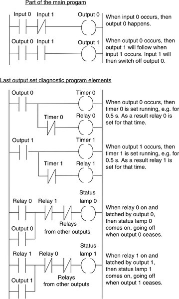
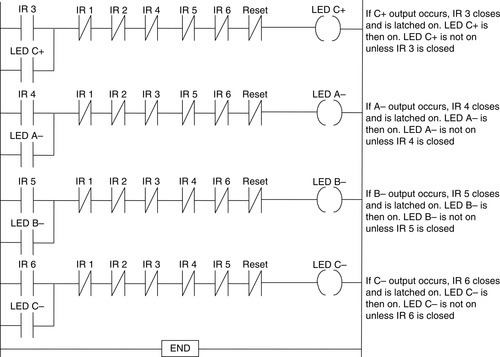
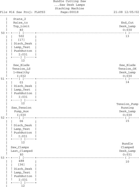
• Last output set. This technique involves the use of status lamps to indicate the last output that has been set during a process that has come to a halt. Such lamps are built into the program so that as each output occurs, a lamp comes on. The lamps that are on thus indicate which outputs are occurring. The program has to be designed to turn off previous status lamps and turn on a new status lamp as each new output is turned on. Figure 13.17 illustrates this concept.
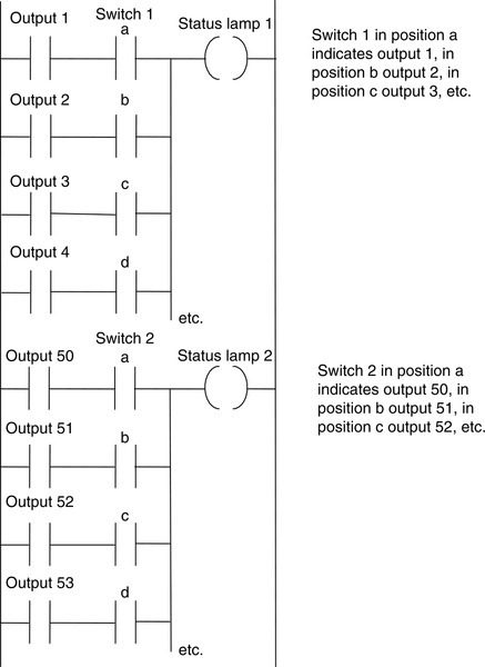
Such a technique can be cumbersome in a large system with many outputs. In such a case, the outputs might be grouped into sets and a status lamp used for each set. A selector switch can then be used within a group to select each output in turn to determine whether it is on. Figure 13.18 illustrates this idea.
As an illustration of the use of this program to indicate which action occurred last, Figure 13.19 shows the program that might be used with a pneumatic system operating cylinders in a sequence. The program indicates at which point in the sequence a fault occurred, such as a piston sticking, and would be added to the main program used to sequence the cylinders. Each of the cylinder movements has a light-emitting diode associated with it, with the last cylinder movement indicated by its LED being illuminated.

• Replication. Where there is concern regarding safety in the case of a fault developing, checks may be constantly used to detect faults. One technique is replication checks, which involve duplicating, that is, replicating, the PLC system. This could mean that the system repeats every operation twice and, if it gets the same result, it is assumed that there is no fault. This procedure can detect transient faults. A more expensive alternative is to have duplicate PLC systems and compare the results given by the two systems. In the absence of a fault, the two results should be the same.
• Expected value checks. Software errors can be detected by checking whether an expected value is obtained when a specific input occurs. If the expected value is not obtained, a fault is assumed to be occurring.
13.4.2 Program Storage
Applications programs may be loaded into battery-backed RAM in a PLC. A failure of the battery supply means a complete loss of the stored programs. An alternative to storing applications programs in battery-backed RAM is to use EPROM. This form of memory is secure against the loss of power. Against the possibility of memory failure occurring in the PLC and loss of the stored application program, a backup copy of each application program should be kept. If the program has been developed using a computer, the backup may be on a CD or a hard disk. Otherwise the backup may be on an EPROM cartridge. The program can then again be downloaded into the PLC without it having to be rewritten.
13.5 System Documentation
The documentation is the main guide used by everyday users, including for troubleshooting and fault finding with PLCs. It thus needs to be complete and in a form that is easy to follow. The documentation for a PLC installation should include the following:
• Specification of the control requirements
• Details of the programmable logic controller
• Electrical installation diagrams
• Lists of all input and output connections
• Application program with full commentary on what it is achieving
• Software backups
• Operating manual, including details of all start up and shut down procedures and alarms
13.5.1 Example of an Industrial Program
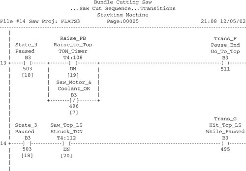
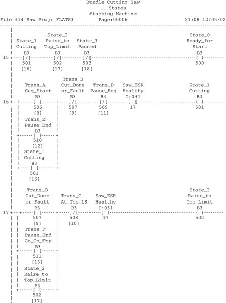
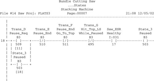
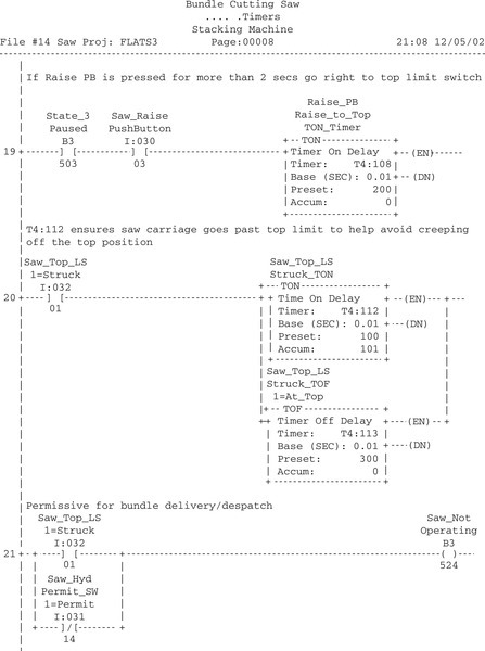
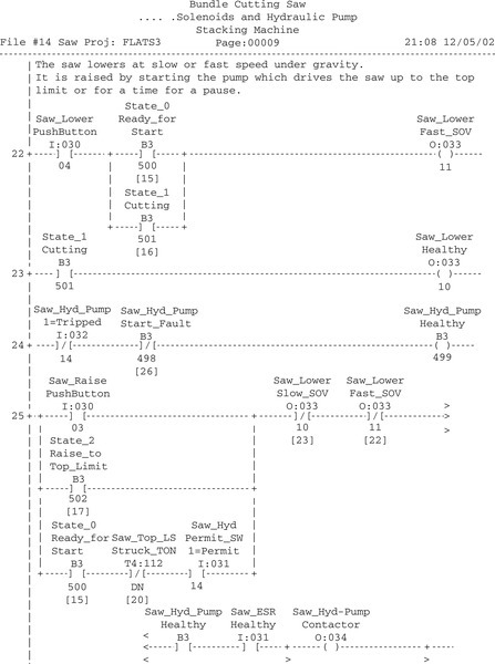
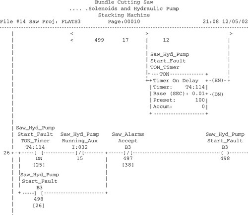
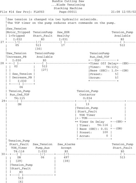
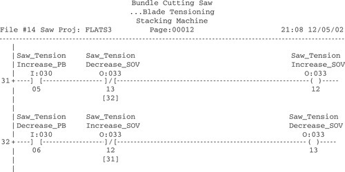
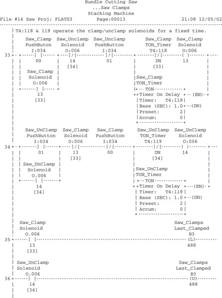
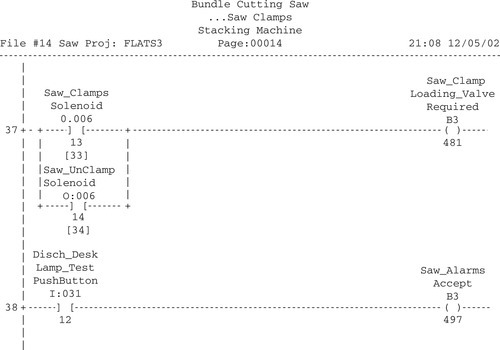
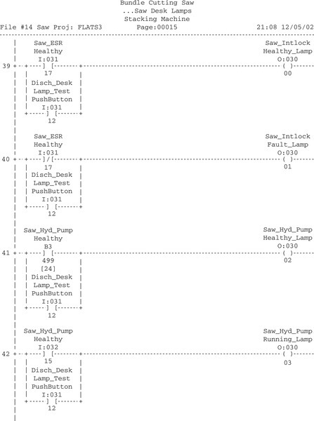
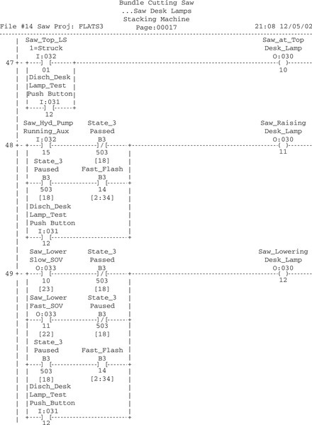
The following is an example of the way a program might appear for a real plant controlled by an Allen-Bradley PLC5; I am grateful to Andrew Parr for supplying it. It illustrates the way a program file is documented to aid in clarification and the safety and fault indication procedures that are used. Note that the right-hand power rail has been omitted, which is allowable in IEC 61131-3.
The program is one of about 40 program files in the complete program, each file controlling one area of operation and separated by a page break from the next file. The file that follows controls a bundle-cutting band saw and involves motor controls, desk lamps, and a small state transition sequence.
Note the rung cross-references, such as [38], below B3/497 in rung 2. These are used to show that B3/497 originates, for example, in rung 38 in the current program file. Also note that all instructions are tagged with descriptions and the file is broken down into page sections. The software allows you to go straight to a function via the page titles.
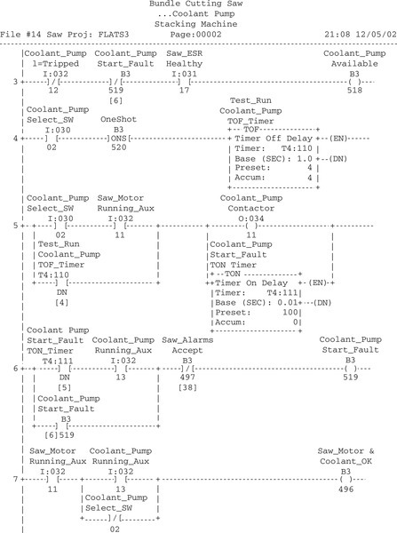
All the motor starter rungs work in the same way. The PLC energizes the contactor and then one second later looks for the auxiliary relay (labeled as Aux in the program file) coming back to say the contactor has energized. If there is a fault that causes the contactor to deenergize, such as a loss of supply, or a trip or open circuit coil, it causes the PLC to signal a fault and deenergize the contactor output so that the machine does not spring into life when the fault is cleared.
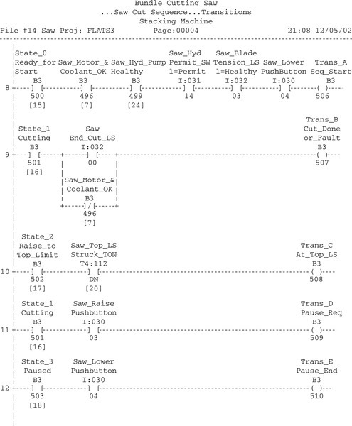
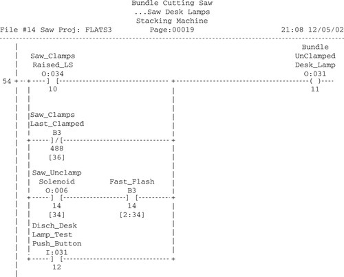
The saw normally sits raised clear of the bundle. To cut the bundle, the blade motor has to be started and the lower push-button pressed (at rung 8). The saw falls under gravity at a fast or slow speed that is set by hydraulic valves. To raise the saw, a hydraulic pump is started to pump oil into the saw support cylinders. At any time the saw can be raised, such as to clear swarf, to what is termed the pause state. Otherwise, cutting continues until the bottom limit is reached. The saw then is raised to the top limit for the next bundle. A cut can be aborted by pressing the raise button for two seconds. While a bundle is being cut, it is held by clamp solenoids.
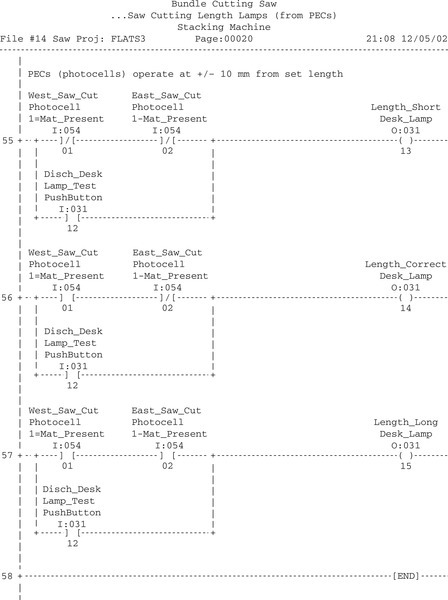
The final three rungs of the program set the length to be cut. There are two photocells about 20 mm apart on a moveable carriage. These are positioned at the required length. The operator runs the bundle in until the first is blocked and the second is clear. These control the long/correct/short desk lamps.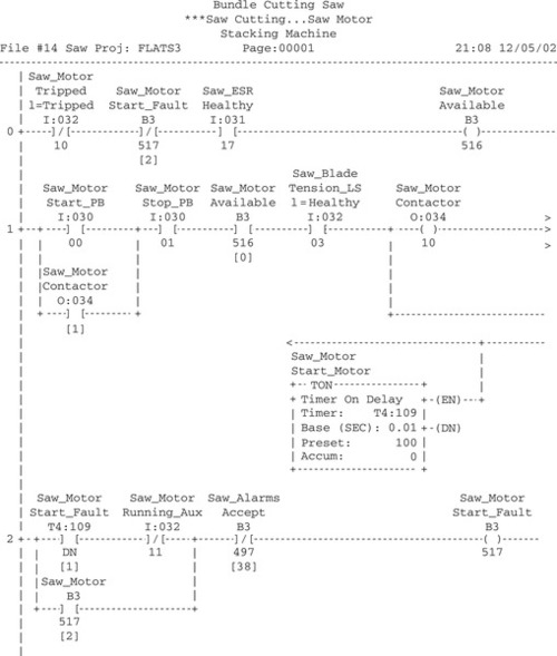


Summary
A systematic approach to the writing of programs can improve the chances of high-quality programs being generated in as short a time as possible. This is likely to involve the following: a definition of what is required, a definition of the algorithm to be used, translation of the algorithm into instructions for the PLC, testing and debugging of the program, and documentation to ensure that any person using the program can understand how it works.
Modern safety legislation charges employers with duties that include making the workplace safe and without risks to health and ensuring that plant and machinery are safe and that safe systems of work are set and followed. An important standard relevant to PLCs is IEC 61508: Functional Safety of Electrical/Electronic/Programmable Electronic Safety-Related Systems. Emergency stop buttons and safety guard switches must be hardwired and not depend on the PLC software for implementation so that, in the situation where there is a failure of the stop switch or PLC, the system is automatically safe. The system must be fail-safe. This can involve two-handed engaging, protective door monitoring, light curtains, safety mats, and emergency stop relays.
Commissioning of a PLC system involves checking that all the cable connections between the PLC and the plant being controlled are complete, safe, and to the required specification and local standards, checking that the incoming power supply matches the voltage setting for which the PLC is set, checking that all protective devices are set to their appropriate trip settings, checking that emergency stop buttons work, checking that all input/output devices are connected to the correct input/output points and giving the correct signals, loading the software, and testing the software. Fault detection techniques include watchdog timing checks, indicators to show last output set, replication, and expected value checks.
The documentation for a PLC installation should include a description of the plant, specification of the control requirements, details of the programmable logic controller, electrical installation diagrams, lists of all input and output connections, the application program with full commentary on what it is achieving, software backups, and an operating manual, including details of all startup and shutdown procedures and alarms.
Problems
Questions 1 through 7 have four answer options: A, B, C, or D. Choose the correct answer from the answer options.
1. The ladder program elements given in Figure 13.20 can be described by a basic algorithm of the type:
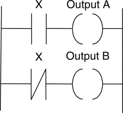
B. IF-THEN-ELSE-ENDIF
C. WHILE-DO-ENDWHILE
D. Not described by A, B, or C
2. Decide whether each of these statements is true (T) or false (F). The term forcing, when applied to a PLC input/output, means using a program to:
(i) Turn on or off inputs/outputs.
(ii) Check that all inputs/outputs give correct responses when selected.
A. (i) T (ii) T
B. (i) T (ii) F
C. (i) F (ii) T
D. (i) F (ii) F
3. Decide whether each of these statements is true (T) or false (F). The term watchdog, when applied to a PLC, means a checking mechanism that:
(i) Excessive currents are not occurring.
(ii) Functions are carried out within prescribed time limits.
A. (i) T (ii) T
B. (i) T (ii) F
C. (i) F (ii) T
D. (i) F (ii) F
4. Decide whether each of these statements is true (T) or false (F). When a PLC is in monitor/test/debug mode, it:
(i) Enables the operation of a program to be simulated.
(ii) Carries out a fault check.
A. (i) T (ii) T
B. (i) T (ii) F
C. (i) F (ii) T
D. (i) F (ii) F
5. When a PLC is in monitor/test/debug mode and the symbol shown in Figure 13.21 occurs, it means that an input is:

B. Correctly operating
C. On
D. Off
6. Decide whether each of these statements is true (T) or false (F). Failure of an input sensor or its wiring, rather than failure of an LED or in the PLC input channel, will show as:
(i) The input LED not coming on.
(ii) Forcing of that input, making the input LED come on.
A. (i) T (ii) T
B. (i) T (ii) F
C. (i) F (ii) T
D. (i) F (ii) F
7. A single output device fails to turn on when the output LED is on. The voltage at the output is tested and found normal, but the voltage at the device is found to be absent. The fault is:
B. A faulty output device
C. A fault in the PLC
D. A fault in the program
8. Explain how, using forcing, the failure of an input sensor or its wiring can be detected.
9. Suggest possible causes of a complete stoppage of the control operation and the PLC with the power-on lamp off.
10. Suggest possible causes of an output LED being on but the output device failing to turn on.
11. Devise a timing watchdog program to be used to switch off a machine if faults occur in any of the systems controlling its actions.
12. Design the program for a pneumatic system for control by a PLC with the cylinder sequence A+, B+, B–, A– and an LED indicating, in the presence of a fault such as a sticking cylinder, at which point in the cycle the fault occurred. Explain the action of all elements in the system.
Lookup Tasks
13. Look up the safety standard IEC61508. You will also find summaries of the main implications of it on the Web.
14. Find out details of light curtain systems that are commercially available.
15. Find out details of electronic safety relays that are commercially available.