Programmable Logic Controllers
Abstract
This chapter is an introduction to control systems, starting with a discussion of relay-controlled systems before discussing the programmable logic controller (PLC) and its general function, hardware forms, and internal architecture. PLCs are widely used for a range of automation tasks in such areas as industrial processes in manufacturing. The IEC standard 61131 is outlined. This overview is followed by more detailed discussion in the following chapters.
This chapter is an introduction to the programmable logic controller (PLC) and its general function, hardware forms, and internal architecture. PLCs are widely used for a range of automation tasks in areas such as industrial processes in manufacturing. This overview is followed by more detailed discussion in the following chapters. For a summary of the history, development, features, and comparison with other control systems, see the Wikipedia entry for Programmable logic controller.
1.1 Controllers
What type of task might a control system handle? It might be required to control a sequence of events, maintain some variable constant, or follow some prescribed change. For example, the control system for an automatic drilling machine (Figure 1.1a) might be required to start lowering the drill when the workpiece is in position, start drilling when the drill reaches the workpiece, stop drilling when the drill has produced the required depth of hole, retract the drill, and then switch off and wait for the next workpiece to be put in position before repeating the operation. Another control system (Figure 1.1b) might be used to control the number of items moving along a conveyor belt and direct them into a packing case. The inputs to such control systems might come from switches being closed or opened; for example, the presence of the workpiece might be indicated by it moving against a switch and closing it, or other sensors such as those used for temperature or flow rates. The controller might be required to run a motor to move an object to some position or to turn a valve, or perhaps a heater, on or off.

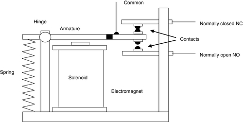
What form might a controller have? For the automatic drilling machine, we could wire up electrical circuits in which the closing or opening of switches would result in motors being switched on or valves being actuated. Thus, as a result, we might have a relay (Figure 1.2) closing or opening contacts which, in turn, switches on the current to a motor and causes the drill to rotate (Figure 1.3). Another switch might be used to activate a relay and switch on the current to a pneumatic or hydraulic valve, which results in pressure being switched to drive a piston in a cylinder and so results in the workpiece being pushed into the required position. Such electrical circuits would have to be specific to the automatic drilling machine. For controlling the number of items packed into a packing case, we could likewise wire up electrical circuits involving sensors and motors. However, the controller circuits we devised for these two situations would be different. In the “traditional” form of control system, the rules governing the control system and when actions are initiated are determined by the wiring. When the rules used for the control actions are changed, the wiring has to be changed.
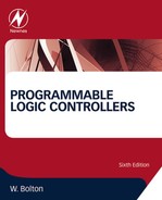
1.1.1 Relay-Controlled Systems
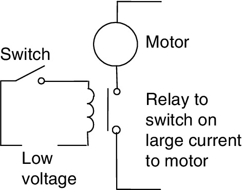
Relay-controlled systems are hard-wired systems. Figure 1.2 shows the basic elements of a simple relay. When a current is switched on to flow through the relay solenoid, normally-closed (NC) contacts open and normally-open (NO) contacts close. These contacts can be used to give control in a system. As an illustration consider a relay being used to operate a pneumatic or hydraulic valve, this then results in pressure being applied to drive a piston to move a workpiece. We can represent the situation by a control drawing. Figure 1.4 shows the standard symbols used for relays and Figure 1.5 shows the control drawing with the vertical lines representing the power rails and the horizontal lines to systems connected between them. The sequence of events is read from the top horizontal line downwards. Thus, in the top line of Figure 1.5(a), when the Off–On switch is closed, the relay is activated. This closes the contacts on the second line and so the solenoid valve is switched on. A more usual control drawing is shown in Figure 1.5(b) which has the relay switched on by a momentary NO push-button switch. This closes two sets of contacts. Contacts 1 latch the push button switch so that when the push stops there is still connection of power to the relay. Contacts 2 switch on the solenoid valve. The relay, and hence power to the solenoid valve, is switched off when the normally closed push-button switch is pressed. The control drawings are obviously only part of the control system as there will need to be further lines for when the solenoid valve has moved the workpiece the required distance so that it stops its action.

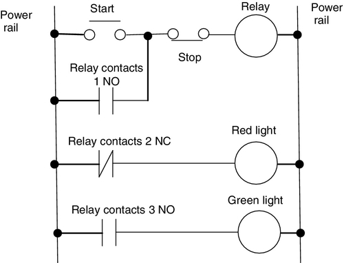
Figure 1.6 shows another example of a relay control system. When the start push button is closed, the relay coil is switched on and latches the push button switch so that the relay remains on until the stop push button is pressed. The relay closes the NO contacts and opens the NC contacts. As a result, the green light is switched on and the red light switches off. When the stop push button is pressed, the current to the relay coil is switched off. This results in the NO contacts opening and the NC contacts closing and so the green light going off and the red light comes on. The next stage in the relay circuit might be a motor that is switched on by NO contacts, so the green light indicates when the motor is running and the red light when it is off.
1.1.2 Microprocessor-Controlled Systems
Instead of hardwiring each control circuit for each control situation, we can use the same basic system for all situations if we use a microprocessor-based system and write a program to instruct the microprocessor how to react to each input signal from, say, switches and give the required outputs to, say, motors and valves. Thus we might have a program of the form:
If switch A closes
Output to motor circuit
If switch B closes
Output to valve circuit
By changing the instructions in the program, we can use the same microprocessor system to control a wide variety of situations.
As an illustration, the modern domestic washing machine uses a microprocessor system. Inputs to it arise from the dials used to select the required wash cycle, a switch to determine that the machine door is closed, a temperature sensor to determine the temperature of the water, and a switch to detect the level of the water. On the basis of these inputs the microprocessor is programmed to give outputs that switch on the drum motor and control its speed, open or close cold and hot water valves, switch on the drain pump, control the water heater, and control the door lock so that the machine cannot be opened until the washing cycle is completed.
1.1.3 The Programmable Logic Controller
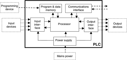
A programmable logic controller (PLC) is a special form of microprocessor-based controller that uses programmable memory to store instructions and to implement functions such as logic, sequencing, timing, counting, and arithmetic in order to control machines and processes (Figure 1.7). It is designed to be operated by engineers with perhaps a limited knowledge of computers and computing languages. They are not designed so that only computer programmers can set up or change the programs. Thus, the designers of the PLC have preprogrammed it so that the control program can be entered using a simple, rather intuitive form of language (see Chapter 4). The term logic is used because programming is primarily concerned with implementing logic and switching operations; for example, if A or B occurs, switch on C; if A and B occurs, switch on D. Input devices (that is, sensors such as switches) and output devices (motors, valves, etc.) in the system being controlled are connected to the PLC. The operator then enters a sequence of instructions, a program, into the memory of the PLC. The controller then monitors the inputs and outputs according to this program and carries out the control rules for which it has been programmed.

PLCs have the great advantage that the same basic controller can be used with a wide range of control systems. To modify a control system and the rules that are to be used, all that is necessary is for an operator to key in a different set of instructions. There is no need to rewire. The result is a flexible, cost-effective system that can be used with control systems, which vary quite widely in their nature and complexity. When compared with relay systems, PLCs:
• Can easily implement changes as changes are implemented in software rather than more complex hardware modifications that would be the case with a relay system
• Can be readily expanded by adding new modules to the PLC whereas hardware changes are necessary with relay systems
• Are more robust and reliable than relay systems with their large number of mechanical components
• Are more compact than relay systems
• Require less maintenance than relay systems
• Can operate faster than relay systems.
PLCs are similar to computers, but whereas computers are optimized for calculation and display tasks, PLCs are optimized for control tasks and the industrial environment. Thus when compared to computers, PLCs:
• Are rugged and designed to withstand vibrations, temperature, humidity, and noise. The common personal computer is not designed for harsh environments.
• Have interfacing for inputs and outputs already inside the controller. PLCs in a rack format are easy to expand to tackle a larger number of inputs/outputs.
• Are easily programmed and have an easily understood programming language that is primarily concerned with logic and switching operations. As a consequence, they are more user friendly.
• They are not so good at long term data storage and analysis as personal computers.
• Personal computers are more liable to crash than PLCs that have greater reliability.
The first PLC was developed in 1969. PLCs are now widely used and extend from small, self-contained units for use with perhaps 20 digital inputs/outputs to modular systems that can be used for large numbers of inputs/outputs, handle digital or analog inputs/outputs, and carry out proportional-integral-derivative control modes. They are used in automation tasks for industrial processes in manufacturing such as machining, materials handling, automated assembly and packaging. However, for very simple automation tasks such as a household washing machine, a cheaper alternative is likely to be used. Where very demanding tasks are involved, for example aircraft flight control, a computer is likely to be used because of its ability to handle complex mathematics and its high speed of operation.
1.2 Hardware
Typically a PLC system has the basic functional components of processor unit, memory, power supply unit, input/output interface section, communications interface, and the programming device. Figure 1.8 shows the basic arrangement. The constituent elements are:
• The processor unit or central processing unit (CPU) is the unit containing the microprocessor. This unit interprets the input signals and carries out the control actions according to the program stored in its memory, communicating the decisions as action signals to the outputs.
• The power supply unit is needed to convert the mains AC voltage to the low DC voltage necessary for the processor and the circuits in the input and output interface modules.
• The programming device is used to enter the required program into the memory of the processor. The program is developed in the device and then transferred to the memory unit of the PLC.
• The memory unit is where the program containing the control actions to be exercised by the microprocessor is stored and where the data is stored from the input for processing and for the output.
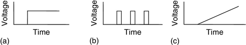
• The input and output sections are where the processor receives information from external devices and communicates information to external devices. The inputs might thus be from switches, as illustrated in Figure 1.1a with the automatic drill, or other sensors such as photoelectric cells, as in the counter mechanism in Figure 1.1b, temperature sensors, flow sensors, or the like. The outputs might be to motor starter coils, solenoid valves, or similar things. (Input and output interfaces are discussed in Chapter 2.) Input and output devices can be classified as giving signals that are discrete, digital or analog (Figure 1.9). Devices giving discrete or digital signals are ones where the signals are either off or on. Thus a switch is a device giving a discrete signal, either no voltage or a voltage. Digital devices can be considered essentially as discrete devices that give a sequence of on/off signals. Analog devices give signals of which the size is proportional to the size of the variable being monitored. For example, a temperature sensor may give a voltage proportional to the temperature.
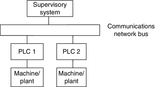
• The communications interface is used to receive and transmit data on communication networks from or to other remote PLCs (Figure 1.10). It is concerned with such actions as device verification, data acquisition, synchronization between user applications, and connection management.
1.3 PLC Architecture
A PLC typically consists of a central processing unit (CPU) containing the system microprocessor, memory, and input/output circuitry. It can effectively be considered to be a unit containing vast numbers of separate relays, counters, timers and data storage units. These, however, do not exist physically in the PLC but are software-simulated.
The storage capacity of a memory unit is specified by the number of binary words that it can store. Thus, if a memory size is 256 words, it can store 256 × 8 = 2048 bits if 8-bit words are used and 256 × 16 = 4096 bits if 16-bit words are used. The term byte is used for a word of length 8 bits. Memory sizes are often specified in terms of the number of storage locations available, with 1K representing the number 210, that is, 1024. Thus a 4 Kbyte memory can store 4096 bytes, a 50 Kbyte memory 51 200 bytes.
1.3.1 Input/Output Unit
The input/output (I/O) unit in a PLC provides the circuitry for the interface between the system and the outside world, allowing for connections to be made through input/output channels to input devices such as sensors and output devices such as motors and solenoids. It is also through the input/output unit that programs are entered from a program panel. Every input/output point has a unique address that can be used by the CPU. It is like a row of houses along a road; number 10 might be the “house” used for an input from a particular sensor, whereas number 45 might be the “house” used for the output to a particular motor.
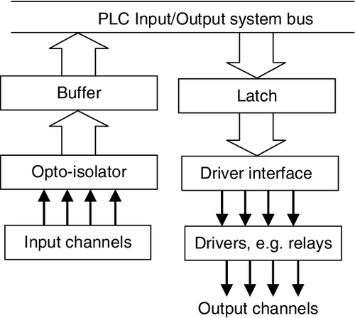
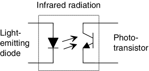
The input/output channels provide isolation and signal conditioning functions so that sensors and actuators can often be directly connected to them without the need for other circuitry (Figure 1.11). Electrical isolation from the external world is usually by means of optoisolators (the term optocoupler is also often used). Figure 1.12 shows the principle of an optoisolator. When a digital pulse passes through the light-emitting diode, a pulse of infrared radiation is produced. This pulse is detected by the phototransistor and gives rise to a voltage in that circuit. The gap between the light-emitting diode and the phototransistor gives electrical isolation, but the arrangement still allows for a digital pulse in one circuit to give rise to a digital pulse in another circuit.
Signal conditioning in the input channel, with isolation, enables a wide range of input signals to be supplied to it so that it is converted into a voltage compatible with the required for the microprocessor in the PLC (see Chapter 3 for more details). A range of inputs might be available with a larger PLC, such as 5 V, 24 V, 110 V, and 240 V digital/discrete, that is, on-off, signals. A small PLC is likely to have just one form of input, such as 24 V.
The output channels enable the PLC outputs to be available in a form suitable for direct connections to external circuits. Outputs are specified as being of relay type, transistor type, or triac type (see Chapter 3 for more details):
• With the relay type, the signal from the PLC output is used to operate a relay and is able to switch currents of the order of a few amperes in an external circuit. The relay not only allows small currents to switch much larger currents but also isolates the PLC from the external circuit. Relays are, however, relatively slow to operate. Relay outputs are suitable for AC and DC switching. They can withstand high surge currents and voltage transients.
• The transistor type of output uses a transistor to switch current through the external circuit. This gives a considerably faster switching action. It is, however, strictly for DC switching and is destroyed by overcurrent and high reverse voltage. For protection, either a fuse or built-in electronic protection is used. Optoisolators are used to provide isolation.
• Triac outputs, with optoisolators for isolation, can be used to control external loads that are connected to the AC power supply. It is strictly for AC operation and is very easily destroyed by overcurrent. Fuses are virtually always included to protect such outputs.
Thus, after signal conditioning with relays, transistors, or triacs, the output from the output channel might be a 24 V, 100 mA switching signal; a DC voltage of 110 V, 1 A, or perhaps 240 V; 1 A AC or 240 V, 2 A AC, from a triac output channel. With a small PLC, all the outputs might be of one type, such as 240 V AC, 1 A. With modular PLCs, however, a range of outputs can be accommodated by selection of the modules to be used.
1.3.2 Sourcing and Sinking
The terms sourcing and sinking are used to describe the way in which DC devices are connected to a PLC. With sourcing, using the conventional current flow direction as from positive to negative, an input device receives current from the input module, that is, the input module is the source of the current (Figure 1.13a). With sinking, using the conventional current flow direction, an input device supplies current to the input module, that is, the input module is the sink for the current (Figure 1.13b). If the current flows from the output module to an output load, the output module is referred to as sourcing (Figure 1.14a). If the current flows to the output module from an output load, the output module is referred to as sinking (Figure 1.14b).
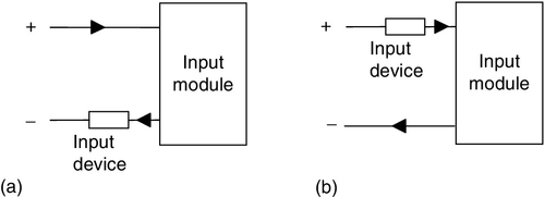
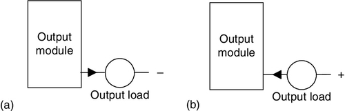
It is important know the type of input or output concerned so that it can be correctly connected to the PLC. Thus, sensors with sourcing outputs should be connected to sinking PLC inputs and sensors with sinking outputs should be connected to sourcing PLC inputs. The interface with the PLC will not function and damage may occur if this guideline is not followed.
1.4 PLC Systems
There are two common types of mechanical design for PLC systems—a single box and the modular/rack types. The single-box type (or, as it's sometimes called, compact or brick) is commonly used for small programmable controllers and is supplied as an integral compact package complete with power supply, processor, memory, and input/output units. Typically such a PLC might have 6, 8, 12, or 24 inputs and 4, 8, or 16 outputs and a memory that can store some 300 to 1000 instructions. For example, the Toshiba PLC brick TAR 116-6S has 8 inputs 120 V ac, 6 relay outputs, and 2 triac outputs while a bigger brick TDR140-6S has 24 inputs 24 V dc, 14 relay outputs and 2 triac outputs. Some compact systems have the capacity to be extended to cope with more inputs and outputs by linking input/output boxes to them.
Figure 1.15 shows an example of an Omron compact PLC for machine control, the CP1L. For this particular model, four CPU sizes are available, each with a choice of relay or transistor outputs. The combination of power supply, output, and the number of I/O points can be selected to meet the requirements. The base input/output brick, depending on the model concerned, has 10, 14, 20 or 30 inputs/outputs (I/O). The 10 I/O brick has 6 digital input points and four outputs, the 14 I/O brick has 8 digital input points and 6 outputs, the 20 I/O brick has 12 digital input points and 8 outputs and the 30 I/O brick has 18 digital input points and 12 outputs. The model can be selected to have outputs as relay or transistor sinking or sourcing. The 14, 20 and 30 I/O models can be extended to give more inputs/output, e.g. the 14 I/O model can be extended to give 54 input/outputs.
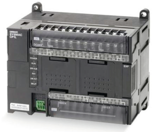
Figure 1.16 shows the Mitsubishi FX3U compact PLC and Table 1.1 and Table 1.2 gives details of models in that Mitsubishi range.
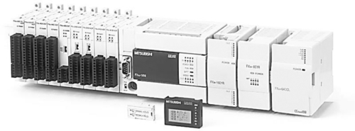
Table 1.1
MELSEC FX Series Product Range
| Type | FX3S | FX3GE | FX3G | FX3U | FX3UC |
| Power supply | 100–240 VAC/24 VDC | 100–240 VAC | 100–240 VAC/24 VDC | 100–240 VAC/24 VDC | 24 VDC |
| No. of inputs | 6–16 | 14–16 | 8–36 | 8–64 | 8–48 |
| No. of outputs | 4–14 | 10–14 | 8–24 | 8–64 | 8–48 |
| Digital outputs | Relay, transistor | Transistor | |||
| Program cycle period per logical instruction | 0.21 s | 0.21–0.42 s | 0.21–0.42 s | 0.065 s | 0.065 s |
| User memory | 4 k steps EEPROM (internal), EEPROM/EPROM cassettes (optional) | 32 k steps EEPROM (internal), EEPROM/EPROM cassettes (optional) | 32 k steps EEPROM (internal), EEPROM cassettes (optional) | 64 k steps (standard), FLROM cassettes (optional) | 64 k steps (standard), EEPROM cassettes (optional) |
| Dimensions in mm (WxHxD) | 60–100x90x75 | 130–175x90x86 | 90–175x90x86 | 130–350x90x86 | 34–86x90x74 |
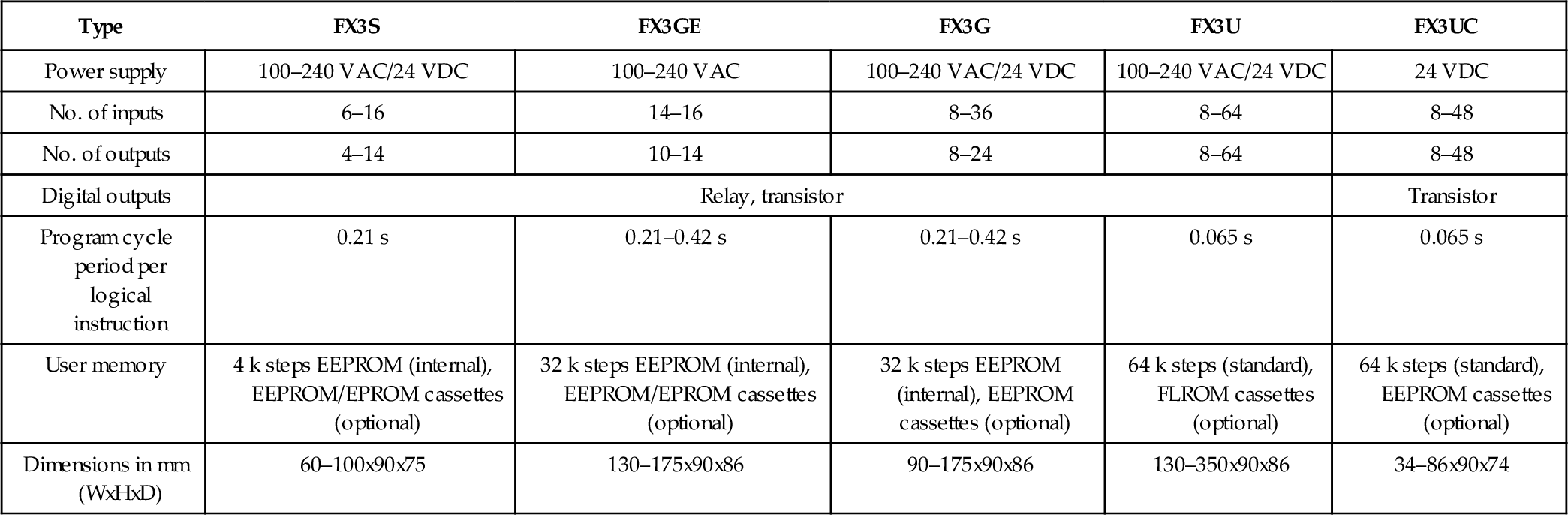
By permission of Mitsubishi Electric Automation, Inc.
Table 1.2
FX3U Main Units with 16 I/O
| Model Number | FX3U-16MR/DS | FX3U-16MR/ES | FX3U-16MT/DSS | FX3U-16MT/DS | FX3U-16MT/ESS | FX3U-16MT/ES |
| Stocked Item | S | S | S | S | S | S |
| Rating | UL • cUL • CE (EMC) | |||||
| Integrated Inputs/Outputs | 16 | 16 | 16 | 16 | 16 | 16 |
| Power Supply | 24VDC | 100-240VAC | 24VDC | 24VDC | 100-240VAC | 100-240VAC |
| Integrated Inputs | 8 | 8 | 8 | 8 | 8 | 8 |
| Integrated Outputs | 8 | 8 | 8 | 8 | 8 | 8 |
| Output Type | Relay | Relay | Transistor (Source) | Transistor (Sink) | Transistor (Source) | Transistor (Sink) |
| Power Consumption (W) | 25 | 30 | 25 | 25 | 30 | 30 |
| Weight (kg) | 0.60 | 0.60 | 0.60 | 0.60 | 0.60 | 0.60 |
| Dimensions (W x H x D) mm | 130 x 90 x 86 | 130 x 90 x 86 | 130 x 90 x 86 | 130 x 90 x 86 | 130 x 90 x 86 | 130 x 90 x 86 |
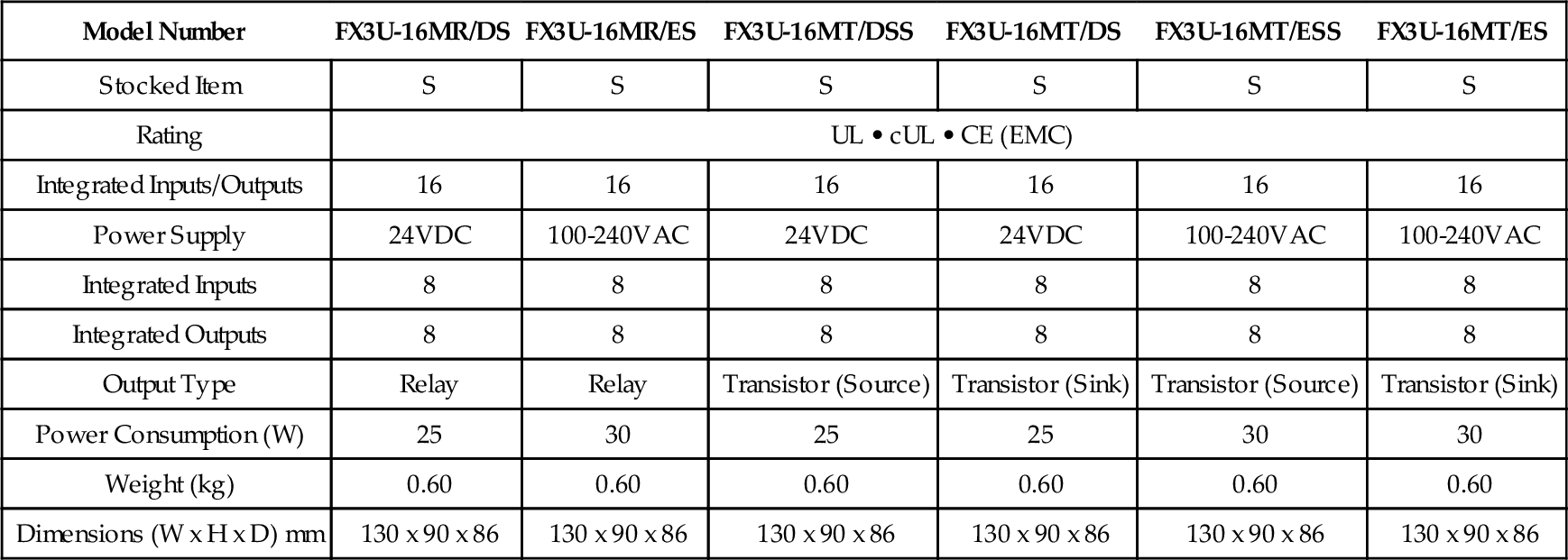
By permission of Mitsubishi Electric Automation, Inc.
Note: the rating row names the organisations for which conformity to certifications are given.
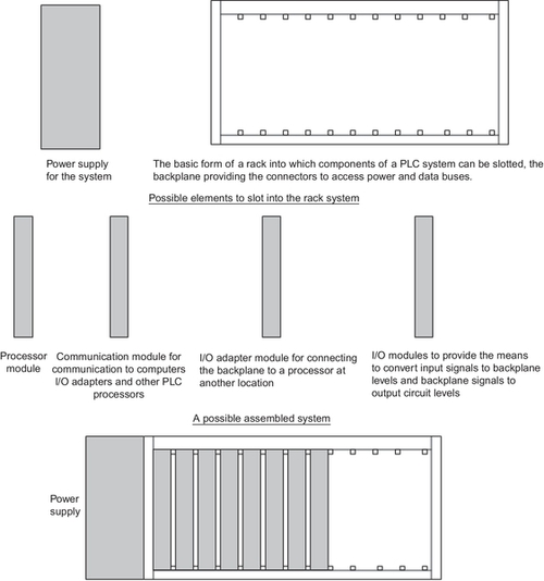
Systems with larger numbers of inputs and outputs are likely to be modular and designed to fit in racks (Figure 1.17). The modular type consists of separate modules for power supply, processor, etc., which are often mounted on rails within a metal cabinet. The rack type can be used for all sizes of programmable controllers and has the various functional units packaged in individual modules that can be plugged into sockets in a base rack. The mix of modules required for a particular purpose is decided by the user and the appropriate ones then plugged into the rack. Thus it is comparatively easy to expand the number of input/output (I/O) connections by just adding more input/output modules or to expand the memory by adding more memory units. The power and data interfaces for modules in a rack are provided by copper conductors in the backplane of the rack. When modules are slid into a rack they engage with connectors in the backplane.
An example of such a modular system is provided by the Allen-Bradley PLC-5 PLC of Rockwell Automation which, at a minimum, will consist of the power supply, a programmable controller module and Input/Output (generally abbreviated to I/O) modules. There are a number of chassis available for mounting modules:
• Chassis. Some 1771 I/O chassis are built for back-panel mounting and some are built for rack mounting and are available in sizes of 4, 8, 12, or 16 I/O module slots.
• Controller module. PLC-5 controllers are available for a range of I/O capacity and memory size, e.g. PLC-5/11 with a maximum number of I/O of 512 and a maximum memory of 8000 words (see Chapter 3 for an explanation of the term ‘word’) and PLC-5/20 with a total number of I/O of 512 and a maximum memory of 16 000 words. They can be configured for a variety of communication networks, e.g. PLC-5/20C for use with ControlNet and PLC-5/20E for use with the Ethernet. They are single-slot modules that are placed in the left-most slot of a 1771 I/O chassis.
• I/O modules. The 1771 I/O modules are available in densities of 8, 16, or 32 I/O per module for signal interfaces to ac and dc sensors and actuators. Digital I/O modules have digital I/O circuits that interface to on/off sensors such as pushbutton and limit switches; and on/off actuators such as motor starters, pilot lights, and annunciators. Analog I/O modules perform the required A/D and D/A conversions using up to 16-bit resolution. Analog I/O can be user-configured for the desired fault-response state in the event that I/O communication is disrupted. This feature provides a safe reaction/response in case of a fault, limits the extent of faults, and provides a predictable fault response. 1771 I/O modules include optical coupling and filter circuitry for signal noise reduction. Digital I/O modules cover electrical ranges from 5 to 276 V AC or DC and relay contact output modules are available for ranges from 0 to 276V AC or 0 to 175 V DC. A range of analog signal levels can be accommodated, including standard analog inputs and outputs and direct thermocouple and RTD temperature inputs. As an illustration, there is the 1771-1B digital input module for 8 inputs with voltages in the range 10 to 27 V, the 1771-0VN for 32 digital outputs with voltages in the range 10 to 30 V, the analog input module 1771-NIV for 8 inputs at ± 5 V dc, ± 20 mA and the analog output 1771-OFE2 for 4 outputs in the range 4 to 20 mA. A PLC-5 processor can communicate with I/O across a DeviceNet or Universal Remote I/O link.
• Communication modules. Communication modules can be used to add further communication ports to the PLC-5 controller beyond that provided by a controller module.
1.4.1 Security
Because PLCs can be connected to networks and contain real-time operating systems, there is the problem of security in that networks can be hacked and information fall into unauthorized hands or viruses inserted. PLCs can also be attacked when a computer they communicate with has been attacked.
1.5 Programs
Programs for use with PLCs can be written in a number of formats. To make it easier for engineers with no great knowledge of programming to write programs for PLCs, ladder programming was developed. Most PLC manufacturers adopted this method of writing programs; however, each tended to develop its own versions and so an international standard has been adopted for ladder programming and indeed all the methods used for programming PLCs. The standard, published in 1993, is International Electrotechnical Commission (IEC) 1131-3, now referred to as IEC 61131-3. The latest edition, dated 2013, is a compatible extension of the earlier version.
The IEC 61131-3 programming languages are ladder diagrams (LAD), instruction list (IL), sequential function charts (SFC), structured text (ST), and function block diagrams (FBD). The standard includes a library of pre-programmed functions and function blocks. Note that a function is the term used for a pre-programmed calculation, for example a function that gives the average value of two inputs, whereas the term function block is used when inputs are evaluated and give a value to an output, for example a counter function block which counts up the pulses to its input and gives an output signal when the count has reached a particular value. These are parts of a control program that is packaged so that it can be used in different parts of the same program or in different programs. The IEC standard gives formal definitions for each input and output parameter so that function blocks designed can different programmers can be readily interconnected. Any PLC that is IEC compliant supports these functions as a library with the code being written in a prom of flash ram on the device.
Two of the languages are graphical, i.e. structured text and instruction list, and so are entered into the programming device from a keyboard, one line at a time. The other languages, ladder diagrams, sequential function charts and function block diagrams, are graphical and so a program can be built up with graphical elements on the screen of the programming device.
1.5.1 The IEC Standard
The IEC 61131 standard covers the complete life cycle of PLCs:
Part 1: General definition of basic terminology and concepts.
Part 2: Electronic and mechanical equipment requirements and verification tests for PLCs and associated equipment.
Part 3: Programming languages. Five languages are defined: ladder diagram (LAD), sequential function charts (SFC), function block diagram (FBD), structured text (ST), and instruction list (IL).
2. Normative references
3. Terms and definitions
4. Architectural models
5. Compliance
6. Common elements
7. Textural languages (instruction list and structured text)
8. Graphic languages (ladder diagram and function block diagram)
Annex A: Formal specification of the language elements
Annex B: List of major changes and extensions of the third edition
Part 4: Guidance on selection, installation, and maintenance of PLCs.
Part 5: Software facilities needed for communication with other devices based on the Manufacturing Messaging Specification (MMS).
Part 6: Communications via fieldbus software facilities.
Part 7: Fuzzy control programming.
Part 8: Guidelines for the implementation of PLC programming languages defined in Part 3.
IEC 61131-6 covers the methods of programming for PLCs. Ladder programming (see Chapter 5) has evolved from electrical wiring diagrams for relay control systems, as in Figure 1.4, and has the advantage of being readily understood by those familiar with electrical wiring diagrams. It also has the advantage of enabling a maintenance engineer to readily trace faults as most programming stations tend to provide an animated display which shows the live state of contacts on the rungs of ladders. Ladder programming can be used to build quite large programs but is not so convenient when subroutines or program blocks are involved. Also programs that involve large numbers of sequences can prove unwieldy with the control of a sequence being mixed in with the application. While simple arithmetic operations can be carried out with ladder programs more complex calculations are rather cumbersome. Despite these issues, ladder programming is very widely used as it is so readily written and understood. Sequential function charts (see Chapter 6) have the merit of displaying all the operational states of a system, all the possible changes of the states and the conditions under which the changes can occur. They are better for showing sequences than ladder programs. Function block diagrams (see Chapter 5) have the advantage as a programming tool or making use of blocks of reusable software elements, logic gates being an example of such blocks. Structured text (see Chapter 6) is a programming language that strongly resembles the programming language Pascal. Instruction list (see Chapter 6) has a relatively simple structure and is useful for dealing with small programs where there only a few decision points and a limited number of changes in program execution flow. It is also harder to follow the program flow.
The IEC 61131-5 standard deals with PLC communications, as outlined in Figure 1.11, and so is concerned with the facilities that are relevant to allow PLCs that are connected by a communications network to exchange data and control information. It states the status information to be provided in a standard format at each subsystem in order to facilitate communication.
1.5.2 Programming PLCs
A programming device can be a handheld device, a desktop console, or a computer. Only when the program has been designed on the programming device and is ready is it transferred to the memory unit of the PLC.
• Handheld programming devices will normally contains enough memory to allow the unit to retain programs while being carried from one place to another.
• Desktop consoles are likely to have a visual display unit with a full keyboard and screen display.
• Personal computers are widely used for programming PLCs. A major advantage of using a computer is that the program can be stored on the hard disk or a CD and copies easily made. The computer is connected to the PLC by Ethernet, RS-232, RS-485 or RS-422 cabling.
PLC manufacturers have programming software for their PLCs. For example, Mitsubishi has MELSOFT. Mitsubishi's iQ Works software is a suite of four MELSOFT software packages that enable intuitive programming and setup of an iQ Platform system, including system/network configuration, Q and FX Series programming, Q Motion Controller and Servo setup, GOT1000 HMI screen design. Simulators and additional configuration software have been integrated into the base software, and Label programming across the entire system has been implemented. MELSOFT Navigator is the heart of iQ Works integrating the other MELSOFT programs included with iQ Works. Functions such as system configuration design, batch parameter setting, system labels, and batch read all help to reduce the total cost of ownership (TCO). MELSOFT GX Works 2 is the PLC maintenance and programming software. It supports all MELSEC controllers from the compact PLCs of the MELSEC FX series to the modular PLCs including MELSEC System Q and uses a Windows based environment. It supports the programming methods (see Chapter 4) of instruction list (IL), ladder diagram (LD) and sequential function chart (SFC) languages. You can switch back and forth between IL and LD at will while you are working. You can program your own function blocks, and a wide range of utilities is available for configuring special functions. The package includes powerful editors and diagnostics functions for configuring MELSEC networks and hardware, and extensive testing and monitoring functions to help get applications up and running quickly and efficiently. It offers offline simulation for all PLC types and thus enables simulation of all devices and application responses for realistic testing.
As another illustration, Siemens has SIMATIC STEP 7. This fully complies with the international standard IEC 61131-3 for PLC programming languages. With STEP 7, programmers can select from among various programming languages. Besides LAD and FBD, STEP 7 Basis also includes the IL programming language. Other additional options are available for IEC 61131-3 programming languages such as ST, called SIMATIC S7-SCL, or SFC, called SIMATIC S7-Graph, which provides an efficient way to describe sequential control systems graphically. Features of the whole engineering system include system diagnostic capabilities, process diagnostic tools, PLC simulation, remote maintenance, and plant documentation. S7-PLCSIM is an optional package for STEP 7 that allows simulation of a SIMATIC S7 control platform and testing of a user program on a PC, enabling testing and refining prior to physical hardware installation. By testing early in a project's development, overall project quality can be improved. Installation and commissioning can thus be quicker and less expensive because program faults can be detected and corrected early on during development.
Likewise, Rockell Automation have RSLogix for the Allen-Bradley PLC-5 family of PLCs. The RSLogix™ family of IEC-1131-compliant ladder logic programming packages have flexible, easy-to-use editors, common look-and-feel, diagnostics and troubleshooting tools and powerful, time-saving features and functionality. This family of products has been developed to operate on Microsoft® Windows® operating systems. RSLogix™ 5 supports the Allen-Bradley PLC-5® family of programmable controllers.
Summary
A programmable logic controller (PLC) is a special form of microprocessor-based controller that uses a programmable memory to store instructions and to implement functions such as logic, sequencing, timing, counting, and arithmetic to control machines and processes and is designed to be operated by engineers with perhaps a limited knowledge of computers and computing languages.
Typically, a PLC system has the basic functional components of processor unit, memory, power supply unit, input/output interface section, communications interface, and programming device. To operate the PLC system there is a need for it to access the data to be processed and the instructions, that is, the program, that informs it how the data is to be processed. Both are stored in the PLC memory for access during processing. The input/output channels provide isolation and signal conditioning functions so that sensors and actuators can often be directly connected to them without the need for other circuitry. Outputs are specified as being of relay type, transistor type, or triac type. The communications interface is used to receive and transmit data on communications networks from or to other remote PLCs. There are two common types of mechanical design for PLC systems—a single box and the modular/rack types.
The IEC 61131 defined the standards for PLCs, with 61131-3 defining the programming languages: ladder diagrams (LAD), instruction list (IL), sequential function charts (SFC), structured text (ST), and function block diagrams (FBD).
Problems
Questions 1 through 6 have four answer options: A, B, C or D. Choose the correct answer from the answer options.
B. Programmable local computer
C. Personal logic controller
D. Programmable logic controller
2. Decide whether each of these statements is true (T) or false (F): A transistor output channel from a PLC:
(i) Is used for only DC switching.
(ii) Is isolated from the output load by an optocoupler.
Which option best describes the two statements?
A. (i) T (ii) T
B. (i) T (ii) F
C. (i) F (ii) T
D. (i) F (ii) F
3. Decide whether each of these statements is true (T) or false (F): A relay output channel from a PLC:
(i) Is used for only DC switching.
(ii) Can withstand transient overloads.
Which option best describes the two statements?
A. (i) T (ii) T
B. (i) T (ii) F
C. (i) F (ii) T
D. (i) F (ii) F
4. Decide whether each of these statements is true (T) or false (F): A triac output channel from a PLC:
(i) Is used for only AC output loads.
(ii) Is isolated from the output load by an optocoupler.
Which option best describes the two statements?
A. (i) T (ii) T
B. (i) T (ii) F
C. (i) F (ii) T
D. (i) F (ii) F
5. Decide whether each of these statements is true (T) or false (F): The term sourcing can be used for a device connected to a PLC when:
(i) The input module of the PLC receive current from the input device.
(ii) The output module of the PLC supplies current to the output load.
Which option best describes the two statements?
A. (i) T (ii) T
B. (i) T (ii) F
C. (i) F (ii) T
D. (i) F (ii) F
6. Decide whether each of these statements is true (T) or false (F): The reason for including optocouplers on input/output units is to:
(i) Provide a fuse mechanism that breaks the circuit if high voltages or currents occur.
(ii) Isolate the CPU from high voltages or currents.
Which option best describes the two statements?
A. (i) T (ii) T
B. (i) T (ii) F
C. (i) F (ii) T
D. (i) F (ii) F
7. Draw a block diagram showing in very general terms the main units in a PLC.
8. State the characteristics of the relay, transistor, and triac types of PLC output channels.
9. How many bits can a 2K memory unit store?
10. A PLC model has a number of different CPU units that can be ordered. One model has 10 I/O terminals of 6 DC outputs and 4 outputs and can be ordered for use with either AC or DC power supplies. The outputs can be selected as either relay output or transistor output with two forms of transistor output available –namely, sink or source type. Explain the capability of such a PLC and the significance of the various forms of output.
Lookup Tasks
11. Google “programmable logic controllers” on the Internet and look at the forms and specifications of PLCs available from various manufacturers. Then find a suitable PLC to meet a particular specification, such as one that would be suitable for six DC inputs and six relay outputs, or possibly six sinking transistor outputs, and a module system that would be suitable for five DC sourcing inputs, four DC sinking inputs, and 12 DC sinking transistor outputs.
12. Look up the IEC 61131-3 standard and find out what it covers.