Digital Systems
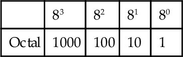
Digital systems work with inputs, which are essentially just off/on signals, with the two signal levels represented by 0 and 1. These are termed binary digits. The number system used for everyday calculations is the denary or decimal system. This is based on the use of 10 digits: 0, 1, 2, 3, 4, 5, 6, 7, 8, 9. With a number represented by this system, the digit position in the number indicates the weight attached to each digit, the weight increasing by a factor of 10 as we proceed from right to left. Hence we have:
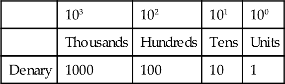
Thus if we have the denary number 1234, we have 1 with a place value of 103, 2 with a place value of 102, 3 with a place value of 101, and 4 with a place value of 100. Counting can, however, be done to any base. The denary system is convenient mainly because we have 10 fingers. If we had only two fingers, our system for everyday counting would probably have been different. Computers, and hence PLC systems, are based on counting in twos because it is convenient for their systems, their two digits being effectively just the off and on signals. When working with PLCs, other base number systems are also used; for example, input and output addresses are often specified using the octal system, that is, base 8. However, the PLC itself works with binary numbers. In this chapter we take a look at the various number systems.
We also take an introductory look at logic systems. A Combinational logic systems take binary inputs and combine them to give a binary output. The relationship between the inputs and the output can be described by truth tables. With such systems, the output of a particular combination of inputs is determined only by their state at the instant of time concerned. However, with sequential logic systems the output is influenced by the history of the past inputs as well as by the present inputs. Both combinational logic and sequential logic systems are introduced in this chapter.
3.1 The Binary System
The binary system is based on just two digits: 0 and 1. These are termed binary digits, or bits. When a number is represented by this system, the digit position in the number indicates the weight attached to each digit, the weight increasing by a factor of 2 as we proceed from right to left.
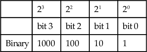
Bit 0 is termed the least significant bit (LSB) and the highest bit in a binary number is termed the most significant bit (MSB). For example, with the binary number 1010, the LSB is the bit at the right end of the number (0 in this example). The MSB is the bit at the left end of the number (1 in this example).
The conversion of a binary number to a denary number involves the addition of the powers of 2 indicated by the place position of a number in the overall number. Thus for the binary number 1010, we have 1 with a place value of 23, 0 with a place value of 22, 1 with a place value of 21, and 0 with a place value of 20, and so the conversion to a denary number is as follows:
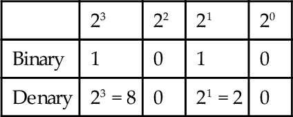
Thus the denary equivalent is 10.
The conversion of a denary number to a binary number involves looking for the appropriate powers of 2. We can do this by successive divisions by 2, noting the remainders at each division. Thus with the denary number 31:
31 ÷ 2 = 15 remainder 1; this gives the LSB
15 ÷ 2 = 7 remainder 1
7 ÷ 2 = 3 remainder 1
3 ÷ 2 = 1 remainder 1; this gives the MSB
The binary number is 11111. The first division gives the LSB because we have just divided 31 by 2, that is, 21, and found 1 left over for the 20 digit. The last division gives the MSB because the 31 has then been divided by 2 four times, that is, 24, and the remainder is 1.
3.2 Octal and Hexadecimal
Binary numbers are used in computers because the two states represented by 0 and 1 are easy to deal with in switching circuits, where they can represent off and on. A problem with binary numbers is that a comparatively small binary number requires a large number of digits. For example, the denary number 9, which involves just a single digit, requires four digits when written as the binary number 1001. The denary number 181, involving three digits, is 10110101 in binary form and requires eight digits. For this reason, octal or hexadecimal numbers are sometimes used to make numbers easier to handle and act as a “halfway house” between denary numbers and the binary numbers with which computers work. Thus, for example, Allen-Bradley uses octal numbering in its PLCs for input and output addresses.
3.2.1 Octal System
The octal system is based on eight digits: 0, 1, 2, 3, 4, 5, 6, 7. When a number is represented by this system, the digit position in the number indicates the weight attached to each digit, the weighting increasing by a factor of 8 as we proceed from right to left. Thus we have:
To convert denary numbers to octal, we successively divide by 8 and note the remainders. Thus the denary number 15 divided by 8 gives 1 with remainder 7; thus the denary number 15 is 17 in the octal system. To convert from octal to denary, we multiply the digits by the power of 8 appropriate to its position in the number. For example, the octal number 365 is 3 × 82 + 6 × 81 + 5 × 80 = 245. To convert from binary into octal, the binary number is written in groups of three bits starting with the least significant bit. For example, the binary number 11010110 would be written as:
Each group is then replaced by the corresponding digit from 0 to 7. For example, the 110 binary number is 6, the 010 is 2, and the 11 is 3. Thus the octal number is 326. As another example, the binary number 100111010 is:
4 7 2 Octal
Octal-to-binary conversion involves converting each octal digit into its 3-bit equivalent. Thus, for the octal number 21, we have 1 as 001 and 2 as 010:
010 001 Binary number
and so the binary number is 010001.
3.2.2 Hexadecimal System
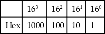
The hexadecimal system (hex) is based on 16 digits/symbols: 0, 1, 2, 3, 4, 5, 6, 7, 8, 9, A, B, C, D, E, F. When a number is represented by this system, the digit position in the number indicates that the weight attached to each digit increases by a factor of 16 as we proceed from right to left. Thus we have:
For example, the decimal number 15 is F in the hexadecimal system. To convert from denary numbers into hex we successively divide by 16 and note the remainders. Thus the denary number 156, when divided by 16, gives 9 with remainder 12, and so in hex is 9C. To convert from hex to denary, we multiply the digits by the power of 16 appropriate to its position in the number. Thus hex 12 is 1 × 161 + 2 × 160 = 18. To convert binary numbers into hexadecimal numbers, we group the binary numbers into fours starting from the least significant number. Thus, for the binary number 1110100110 we have:
3 A 6 Hex number
For conversion from hex to binary, each hex number is converted to its 4-bit equivalent. Thus, for the hex number 1D we have 0001 for the 1 and 1101 for the D:
0001 1101 Binary number
Thus the binary number is 0001 1101.
3.3 Binary Coded Decimals
Because the external world tends to deal mainly with numbers in the denary system and computers with numbers in the binary system, there is always the problem of conversion. There is, however, no simple link between the position of digits in a denary number and the position of digits in a binary number. An alternative method that is often used is the binary coded decimal system (BCD). With this system, each denary digit is coded separately in binary. For example, the denary number 15 has the 5 converted into the binary number 0101 and the 1 into 0001:
0001 0101 Binary number
to give the number 0001 0101 in BCD. With the BCD system, the largest decimal number that can be displayed is a 9, and so the four binary digits are 1001.
To convert a BCD number to a denary number, each group of four binary numbers is separately converted to a denary number. For example, the BCD number 0011 1001 has a denary number of 3 for 0011 and 9 for 1001, and so the denary number is 39.
3 9 Denary number
Numeric data is often entered into PLCs by rotary or thumb-wheel switches with a 0 to 9 range. Thus there may be a bank of such switches, one giving, say, the hundreds, one the tens, and one the ones. The output from each switch is then converted, independently, into binary to give the overall result of a binary coded decimal number. Some PLCs have a function that can be called up to convert such BCD numbers to binary numbers; in other PLCs it has to be done by programming.
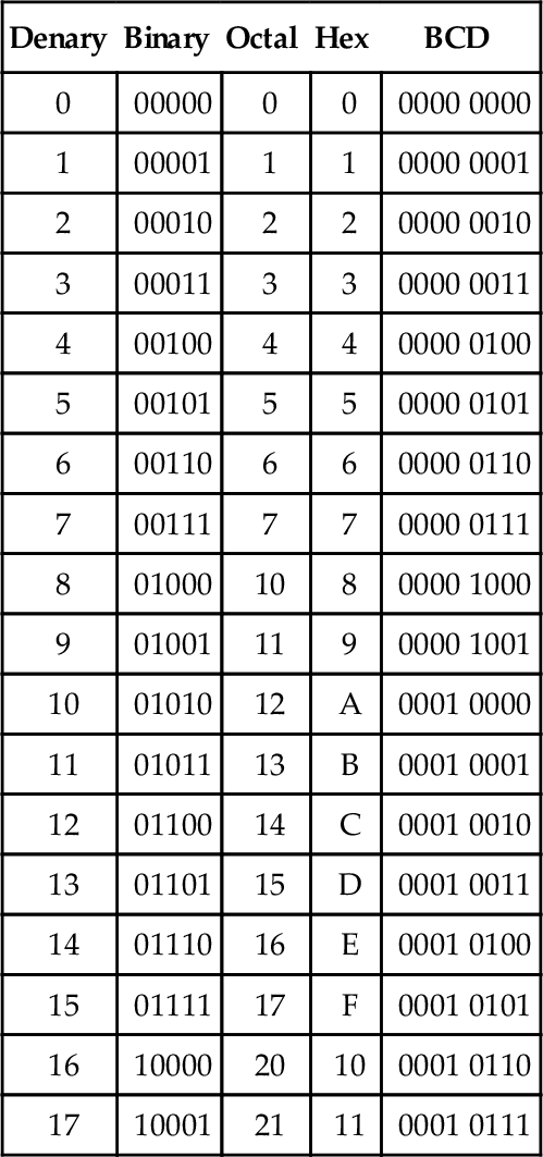
3.4 Numbers in the Binary, Octal, Hex, and BCD Systems
Table 3.1 gives examples of numbers in the denary, binary, octal, hex, and BCD systems.
Table 3.1
Examples of Numbers in Various Systems
| Denary | Binary | Octal | Hex | BCD |
| 0 | 00000 | 0 | 0 | 0000 0000 |
| 1 | 00001 | 1 | 1 | 0000 0001 |
| 2 | 00010 | 2 | 2 | 0000 0010 |
| 3 | 00011 | 3 | 3 | 0000 0011 |
| 4 | 00100 | 4 | 4 | 0000 0100 |
| 5 | 00101 | 5 | 5 | 0000 0101 |
| 6 | 00110 | 6 | 6 | 0000 0110 |
| 7 | 00111 | 7 | 7 | 0000 0111 |
| 8 | 01000 | 10 | 8 | 0000 1000 |
| 9 | 01001 | 11 | 9 | 0000 1001 |
| 10 | 01010 | 12 | A | 0001 0000 |
| 11 | 01011 | 13 | B | 0001 0001 |
| 12 | 01100 | 14 | C | 0001 0010 |
| 13 | 01101 | 15 | D | 0001 0011 |
| 14 | 01110 | 16 | E | 0001 0100 |
| 15 | 01111 | 17 | F | 0001 0101 |
| 16 | 10000 | 20 | 10 | 0001 0110 |
| 17 | 10001 | 21 | 11 | 0001 0111 |
3.5 Binary Arithmetic
Addition of binary numbers uses the following rules:
Consider the addition of the binary numbers 01110 and 10011.
For bit 0 in the sum, 0 + 1 = 1. For bit 1 in the sum, 1 + 1 = 10, and so we have 0 with 1 carried to the next column. For bit 2 in the sum, 1 + 0 + the carried 1 = 10. For bit 3 in the sum, 1 + 0 + the carried 1 = 10. We continue this process through the various bits and end up with 100001.
Subtraction of binary numbers follows these rules:
When evaluating 0 − 1, a 1 is borrowed from the next column on the left that contains a 1. The following example illustrates this method with the subtraction of 01110 from 11011:
For bit 0 we have 1 − 0 = 1. For bit 1 we have 1 − 1 = 0. For bit 2 we have 0 − 1. We thus borrow 1 from the next column and so have 10 − 1 = 1. For bit 3 we have 0 − 1 (remember, we borrowed the 1). Again borrowing 1 from the next column, we then have 10 − 1 = 1. For bit 4 we have 0 − 0 = 0 (remember, we borrowed the 1).
3.5.1 Signed Numbers
The binary numbers considered so far contain no indication as to whether they are negative or positive and are thus said to be unsigned. Since there is generally a need to handle both positive and negative numbers, there needs to be some way of distinguishing between them. This can be done by adding a sign bit. When a number is said to be signed, its MSB is used to indicate the sign of the number; a 0 is used if the number is positive and a 1 is used if it is negative. Thus for an 8-bit number we have:
When we have a positive number, we write it in the normal way, with a 0 preceding it. Thus a positive binary number of 10110 is written as 010110. A negative number of 10110 is written as 110110. However, this is not the most useful way of writing negative numbers for ease of manipulation by computers.
3.5.2 One's and Two's Complements
A more useful way of writing signed negative numbers is to use the two's complement method. A binary number has two complements, known as the one's complement and the two's complement. The one's complement of a binary number is obtained by changing all the 1s in the unsigned number into 0s and the 0s into 1s. Thus if we have the binary number 101101, the one's complement of it is 010010. The two's complement is obtained from the one's complement by adding 1 to the LSB of the one's complement. Thus the two's complement of 101101 becomes 010011.
When we have a negative number, to obtain the signed two's complement, we obtain the two's complement and then sign it with a 1. Consider the representation of the decimal number −6 as a signed two's complement number when the total number of bits is eight. We first write the binary number for +6, that is, 0000110, then obtain the one's complement of 1111001, add 1 to give 1111010, and finally sign it with a 1 to indicate it is negative. The result is thus 11111010.
| Unsigned binary number when sign ignored | 000 0110 |
| One's complement | 111 1001 |
| Add 1 | 1 |
| Unsigned two's complement | 111 1010 |
| Signed two's complement | 1111 1010 |
Table 3.2 lists some signed two's complements for denary numbers, given to 4 bits.
Table 3.2
Signed Two's Complements
| Denary Number | Signed Two's Complement |
| −5 | 1011 |
| −4 | 1100 |
| −3 | 1101 |
| −2 | 1110 |
| −1 | 1111 |
When we have a positive number, we sign the normal binary number with a 0, that is, we write only negative numbers in the two's complement form. A consequence of adopting this method of writing negative and positive numbers is that when we add the signed binary equivalent of +4 and –4, that is, 0000 0100 and 111 1100, we obtain (1)0000 0000 and so zero within the constraints of the number of bits used, the (1) being neglected.
Subtraction of a positive number from a positive number can be considered to be the addition of a negative number to a positive number. Thus we obtain the signed two's complement of the negative number and then add it to the signed positive number. Hence, for the subtraction of the denary number 6 from the denary number 4, we can consider the problem as being (+4) + (−6). Hence we add the signed positive number to the signed two's complement for the negative number.
The MSB, that is, the sign, of the outcome is 1 and so the result is negative. This is the 8-bit signed two's complement for −2.
If we wanted to add two negative numbers, we would obtain the signed two's complement for each number and then add them. Whenever a number is negative, we use the signed two's complement; when it's positive, we use just the signed number.
3.5.3 Floating Point Numbers
Before we discuss floating point numbers, let's consider fixed point numbers. Fixed point numbers are numbers for which there is a fixed location of the point separating integers from fractional numbers. Thus, 15.3 is an example of a denary fixed point number, 1010.1100 an example of a fixed point binary number, and DE.2A an example of a fixed point hexadecimal number. We have, with the 8-bit binary number, four digits before the binary point and four digits after it. When two such binary numbers are added by a computing system, the procedure is to recognize that the fixed point is fixed the same in both numbers, so we can ignore it for the addition, carry out the addition of the numbers, and then insert in the result the binary point in its fixed position. For example, suppose we want to add 0011.1010 and 0110.1000; we drop the binary point to give:
Inserting the binary point then gives 1010.0010.
Using fixed points does present problems. If we are concerned with very large or very small numbers, we could end up with a large number of zeros between the integers and the point, that is, 0.000 000 000 000 023. For this reason, scientific notation is used for such numbers. Thus, the above number might be written as 0.23 × 10⁻¹³ or 2.3 × 10⁻¹⁴ or 23 × 10−15. Likewise, the binary number 0.0000 0111 0010 might be represented as 110010 × 2−12 (the 12 would also be in binary format) or 11001.0 × 2−11 (the 11 being in binary format). Such notation is said to have a floating point.
A floating point number is in the form a × re, where a is termed the mantissa, r the radix or base, and e the exponent or power. With binary numbers the base is understood to be 2, that is, we have a × 2e, and when we know we are dealing with binary numbers we need not store the base with the number. Thus a computing system needs, in addition to storing the sign, that is, whether positive or negative, to store the mantissa and the exponent.
Because with floating point numbers it is possible to store a number in several different ways—for example, 0.1 × 10² and 0.01 × 10³—with computing systems such numbers are normalized. This means that they are all put in the form 0.1 × re. Thus, with binary numbers we have 0.1 × 2e; if we had 0.00001001 it would become 0.1001 × 2−4. To take account of the sign of a binary number, we then add a sign bit of 0 for a positive number and 1 for a negative number. Thus the number 0.1001 × 2−4 becomes 1.1001 × 2−4 if negative and 0.1001 × 2−4 if positive.
Unlike fixed point numbers, floating point numbers cannot be directly added unless the exponents are the same. Thus to carry out addition we need to make the exponents the same.
3.6 PLC Data
Most PLCs operate with a 16-bit word, with the term word meaning the group of bits constituting some information. This allows a positive number in the range 0 to +65535, that is, 1111 1111 1111 1111, to be represented, or a signed number in the range –32768 to +32767 in two's complement, the MSB then representing the sign. Such signed numbers are referred to as integers, with the symbol INT being used with inputs and outputs in programs of such 16-bit words. The term SINT is used for short integer numbers, for which only 8 bits are used, such numbers giving the range –128 to +127. The term DINT is used for double-integer numbers, for which 32 bits are used, such numbers giving the range –231 to +231 – 1. LINT is used for long integer numbers, for which 64 bits are used, such numbers giving the range –263 to +263 – 1. Where numbers are not signed, the symbols UINT, USINT, UDINT, and ULINT are used with integers, short integers, double integers, and long integers.
Decimal fractions are referred to as real or floating point numbers and are represented by the symbol REAL for inputs and outputs in programs. These consist of two 16-bit words; so we might have 1.234567E+03 for the number 1.234 567 × 10+3, the E indicating that the number that follows is the exponent. The term LREAL is used for long real numbers, in which 64 bits are used.
The term BOOL is used for Boolean type data, such data being on/off values, that is, 0 or 1, and thus represented by single bits.
Time duration, such as for the duration of a process, is represented by the IEC standard using the symbols d for days, h for hours, m for minutes, s for seconds, and ms for milliseconds, as, for example, T#12d2h5s3ms or TIME#12d2h5s for 12 days, 2 hours, 5 seconds, and 3 milliseconds. Note that # is the symbol used to indicate that what follows is a numerical quantity.
3.7 Combinational Logic Systems
Consider a system that might be used as an “interlock” to safeguard the operation of a machine. The machine is to start only if two safety conditions are realized: the workpiece is in position and the safety guard is in position. The workpiece in position can be regarded as input A to a system and the safety guard in position as input B (Figure 3.1).
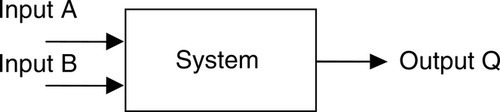
For the input conditions to be expressed in binary form, we require there to be just two possibilities for each input. In this case, if we phrase the question to be posed of each input as having a YES or NO answer, we have just two conditions, which we can write as 1 for YES and 0 for NO. Thus input A can be phrased as follows: “Is the workpiece in position?” and the answer is YES or NO. Input B can be phrased as: “Is the safeguard in position?” and the answer is YES or NO. For this system we require there to be an output when input A is 1 and input B is 1. This relationship between the inputs and output can be tabulated as a truth table showing all the possible combinations of inputs, the combination of which leads to a 1, that is, YES, output, or a 0, that is, NO, output. Table 3.3 is the truth table for this system.
Each input can take only two values, represented by 0 or 1, and are described as two-state variables or logical variables. The complete system constructed with such variable is termed a logic system or logic gates. If the output of such a system depends only on the present states of the inputs, as with the machine “interlock,” it is termed a combinational logic system.
Useful combinational logic systems, which we will meet in Chapter 5, are the AND gate, the OR gate, the NOT gate, the NAND gate, the NOR gate, and the XOR gate. The machine “interlock” system is an example of an AND gate in that input A and input B have to be 1 for the output to be 1.
3.8 Sequential Logic Systems
With a sequential logic system, the present output is influenced by the history of its past inputs as well as by its present input. This is unlike a combinational logic system, where the output only depends on the current state of its inputs. A binary counter can be regarded as a sequential logic system in that the binary output depends on the present input and the sum of the previous inputs. It thus has a “memory.”
Most sequential systems are based on a small number of sequential logic systems called bistables, so-called because they have two stable conditions and can be switched from one to the other by appropriate inputs. Once the circuit has switched, it remains in the other stable state until another input pulse has been received to force it to return to the original state. Basically bistables are a memory device; they can “remember” the effect of an input after the input has been removed.
A latch and a flip-flop, so called because it can, on command, flip into one stable state or flop back again to the other, are bistables. A latch is triggered by the voltage level applied to its input, provided that it has been enabled by its clock input being, generally, high. Flip-flops are devices that change state at either the leading edge or the trailing edge of an enable/clock pulse.
3.8.1 Latches
The clocked D latch has a data input D, outputs Q and ![]() , and an enable/clock input CLK (Figure 3.2). Q is always the complement of
, and an enable/clock input CLK (Figure 3.2). Q is always the complement of ![]() . The logical state of the Q output will follow any changes in the logical state of the D input as long as the clock input remains high. When the clock input goes low, the logical state of the D input at that moment will be retained as the Q output, no matter what changes occur at the D input. When the clock input goes high again, the output Q will again follow any changes in the logical state of the D input. The latch is said to be transparent when the clock is high.
. The logical state of the Q output will follow any changes in the logical state of the D input as long as the clock input remains high. When the clock input goes low, the logical state of the D input at that moment will be retained as the Q output, no matter what changes occur at the D input. When the clock input goes high again, the output Q will again follow any changes in the logical state of the D input. The latch is said to be transparent when the clock is high.
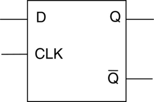
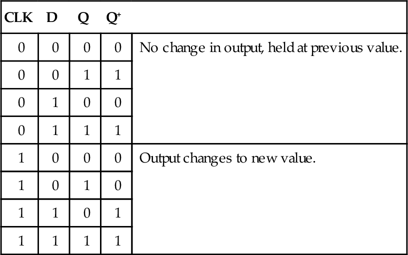
Truth tables can be drawn for latches, but they must take into account the effect of applying a pulse on the clock input. For this reason they are often referred to as function tables. Table 3.4 is the function table for the clocked D latch. Q+ is the state of the Q output after a clock-triggering input.
Table 3.4
Clocked D-Latch
| CLK | D | Q | Q+ | |
| 0 | 0 | 0 | 0 | No change in output, held at previous value. |
| 0 | 0 | 1 | 1 | |
| 0 | 1 | 0 | 0 | |
| 0 | 1 | 1 | 1 | |
| 1 | 0 | 0 | 0 | Output changes to new value. |
| 1 | 0 | 1 | 0 | |
| 1 | 1 | 0 | 1 | |
| 1 | 1 | 1 | 1 |
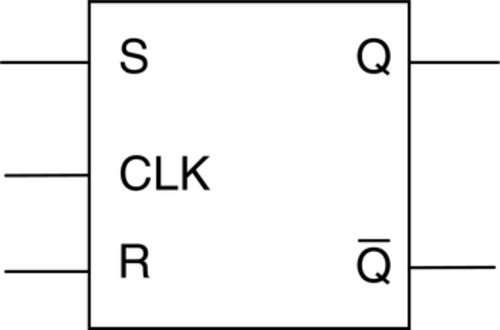
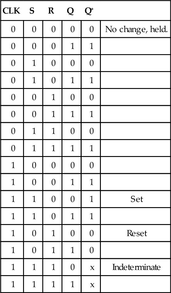
The clocked SR latch has two input terminals, S for set and R for reset; outputs Q and ![]() ; and an enable/clock input CLK (Figure 3.3). Q is always the complement of
; and an enable/clock input CLK (Figure 3.3). Q is always the complement of ![]() . When both S and R are held low, the logical state of the outputs will not change. When S is 1 and R is 0, the logical state of the output Q will become 1, no matter what its value was before. This is termed the set operation. If S is 0 and R is 1, the Q output will be 0, whatever its value was before. This is the reset operation. If both S and R are 1, the operation of the latch is unpredictable, and so this combination of inputs should not be allowed to occur. Table 3.5 shows the function table.
. When both S and R are held low, the logical state of the outputs will not change. When S is 1 and R is 0, the logical state of the output Q will become 1, no matter what its value was before. This is termed the set operation. If S is 0 and R is 1, the Q output will be 0, whatever its value was before. This is the reset operation. If both S and R are 1, the operation of the latch is unpredictable, and so this combination of inputs should not be allowed to occur. Table 3.5 shows the function table.
3.8.2 Flip-Flops
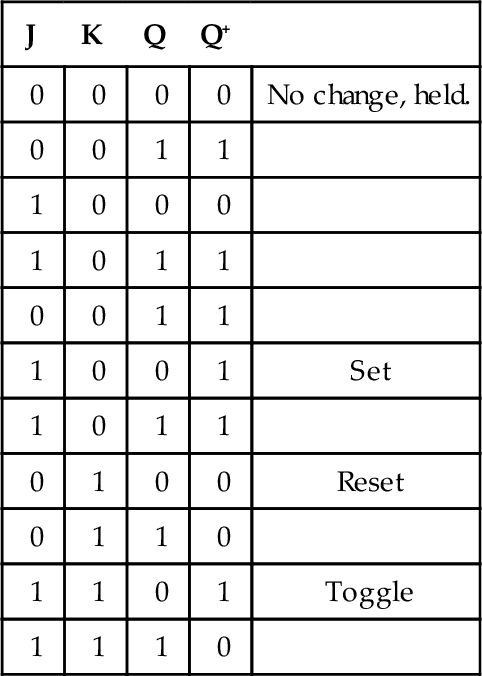
A JK flip-flop has two data input terminals, J and K; a clock input; and two output terminals Q and ![]() (Figure 3.4). A JK flip-flop will change its output state at a clock transition, either at a leading edge or the trailing edge of the clock pulse. A JK flip-flop always changes state when J = K = 1 and might be said to toggle. Table 3.6 is the function table.
(Figure 3.4). A JK flip-flop will change its output state at a clock transition, either at a leading edge or the trailing edge of the clock pulse. A JK flip-flop always changes state when J = K = 1 and might be said to toggle. Table 3.6 is the function table.

Summary
The denary number system is based on the use of 10 digits 0, 1, 2, 3, 4, 5, 6, 7, 8, 9. The binary system is based on just two: 0 and 1. The octal system is based on eight digits: 0, 1, 2, 3, 4, 5, 6, 7. The hexadecimal system is based on the use of 16 digits: 0, 1, 2, 3, 4, 5, 6, 7, 8, 9, A, B, C, D, E, F. The binary coded decimal (BCD) system has each denary digit coded separately into binary.
For the addition of two binary numbers, we have 0 + 0 = 0, 0 + 1 = 1, and 1 + 1=10. For subtraction, we have 0 – 0 = 0, 1 – 0 = 1, and 1 – 1 = 0. Binary numbers that give no indication of whether they are negative or positive are termed unsigned. When a number is signed, the most significant bit indicates the sign of the number—0 if positive and 1 if negative. A binary number has two complements. The one's complement is obtained by changing all the 1s in the unsigned number into 0s and the 0s into 1s. The two's complement is obtained from the one's complement by adding 1 to the least significant bit. When we have a negative number, the signed two's complement number is obtained signing the two's complement with a 1.
A floating point number is in the form a × re, where a is termed the mantissa, r the radix or base, and e the exponent or power. With binary numbers the base is understood to be 2, that is, we have a × 2e; when we know we are dealing with binary numbers we need not store the base with the number. Thus a computing system needs to store the mantissa and the exponent in addition to storing the sign, whether positive or negative.
Most PLCs operate with a 16-bit word, the term word being used for the group of bits constituting some information. Signed numbers are referred to as integers, with the symbol INT used with inputs and outputs in programs of such 16-bit words. SINT is used for short integer numbers where only 8 bits are used. DINT refers to double-integer numbers for which 32 bits are used. LINT is used for long integer numbers where 64 bits are used. Where numbers are not signed, the symbols UINT, USINT, UDINT, and ULINT are used with integers, short integers, double integers, and long integers.
A system constructed with inputs and outputs represented by 0 or 1 is termed a logic system. If the output of such a system depends only on the present states of the inputs, it is termed a combinational logic system. The relationship between the inputs and output can be tabulated as a truth table showing all the possible combinations of inputs that lead to a 1 output and from which a 0 output.
With a sequential logic system, the present output is influenced by the history of its past inputs as well as by its present input, most being based on systems called bistables because they have two stable conditions and can be switched from one to the other by appropriate inputs. Once the circuit has switched, it remains in the other stable state until another input pulse has been received to force it to return to the original state. A latch and a flip-flop are bistables. A latch is triggered by the voltage level applied to its input, provided it has been enabled by its clock input being, generally, high. Flip-flops are devices that change state at either the leading edge or the trailing edge of an enable/clock pulse. Truth tables can be drawn for latches, but they must take account of the effect of applying a pulse on the clock input. For this reason they are often referred to as function tables.
Problems
1. Convert the following binary numbers to denary numbers: (a) 000011, (b) 111111, (c) 001101.
2. Convert the following denary numbers to binary numbers: (a) 100, (b) 146, (c) 255.
3. Convert the following hexadecimal numbers to denary numbers: (a) 9F, (b) D53, (c) 67C.
4. Convert the following denary numbers to hexadecimal numbers: (a) 14, (b) 81, (c) 2562.
5. Convert the following hexadecimal numbers to binary numbers: (a) E, (b) 1D, (c) A65.
6. Convert the following octal numbers to denary numbers: (a) 372, (b) 14, (c) 2540.
7. Convert the following denary numbers to octal numbers: (a) 20, (b) 265, (c) 400.
8. Convert the following octal numbers to binary numbers: (a) 270, (b) 102, (c) 673.
9. Convert the following decimal numbers to BCD equivalents: (a) 20, (b) 35, (c) 92.
10. Convert the following denary numbers to signed two's complement binary 8-bit format: (a) –1, (b) –35, (c) –125.
11. Convert the following signed two's complement binary 8-bit numbers to their denary equivalents: (a) 1111 0000, (b) 1100 1001, (c) 1101 1000.
12. Convert the following binary numbers to normalized floating point numbers: (a) 0011 0010, (b) 0000 1100, (c) 1000.0100.
13. Explain what is meant by the terms combinational logic systems and sequential logic systems.
14. For the following truth tables, which combination of inputs will lead to a 1 output?
15. For a clocked D latch, what inputs will be needed to change the Q output from 0 to 1?
16. Give the function table for a clocked SR latch when the input to S is also applied to R but via a NOT gate, such a gate converting 0 to 1 and 1 to 0.
Lookup Tasks
17. Look up the specifications for (a) an AND gate and (b) a transparent D-type latch.