Shift Registers
The term register is used for an electronic device in which data can be stored. An internal relay (see Chapter 7) is such a device. The shift register is a number of internal relays grouped together that allow stored bits to be shifted from one relay to another. This chapter is about shift registers and how they can be used when a sequence of operations is required or to keep track of particular items in a production system.
11.1 Shift Registers
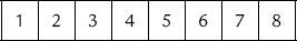
A register is a number of internal relays grouped together, normally 8, 16, or 32. Each internal relay is either effectively open or closed, these states being designated 0 and 1. The term bit is used for each such binary digit. Therefore, if we have eight internal relays in the register, we can store eight 0/1 states. Thus we might have, for internal relays:
and each relay might store an on/off signal such that the state of the register at some instant is:
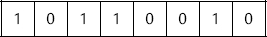
that is, relay 1 is on, relay 2 is off, relay 3 is on, relay 4 is on, relay 5 is off, and so on. Such an arrangement is termed an 8-bit register. Registers can be used for storing data that originate from input sources other than just simple, single on/off devices such as switches.
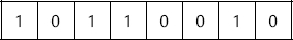
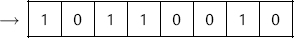
With the shift register it is possible to shift stored bits. Shift registers require three inputs: one to load data into the first location of the register, one as the command to shift data along by one location, and one to reset or clear the register of data. To illustrate this idea, consider the following situation where we start with an 8-bit register in the following state:
Suppose we now receive the input signal 0. This is an input signal to the first internal relay.
Input 0
If we also receive the shift signal, the input signal enters the first location in the register, and all the bits shift along one location. The last bit overflows and is lost.
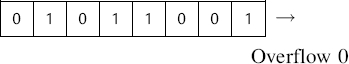
Thus a set of internal relays that were initially on, off, on, on, off, off, on, off are now off, on, off, on, on, off, off, on.
The grouping together of internal relays to form a shift register is done automatically by a PLC when the shift register function is selected. With the Mitsubishi PLC, this is done using the programming code SFT (shift) against the internal relay number that is to be the first in the register array. This then causes a block of relays, starting from that initial number, to be reserved for the shift register.
11.2 Ladder Programs
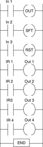
Consider a 4-bit shift register and how it can be represented in a ladder program (Figure 11.1a). The input In 3 is used to reset the shift register, that is, put all the values at 0. The input In 1 is used to input to the first internal relay in the register. The input In 2 is used to shift the states of the internal relays along by one. Each of the internal relays in the register, that is, IR 1, IR 2, IR 3, and IR 4, is connected to an output, these being Out 1, Out 2, Out 3, and Out 4.
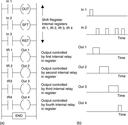
Suppose we start by supplying a momentary input to In 3. All the internal relays are then set to 0 and so the states of the four internal relays IR 1, IR 2, IR 3, and IR 4 are 0, 0, 0, 0. When In 1 is momentarily closed, there is a 1 input into the first relay. Thus the states of the internal relays IR 1, IR 2, IR 3, and IR 4 are now 1, 0, 0, 0. The IR 1 contacts close and we thus end up with an output from Out 1. If we now supply a momentary input to In 2, the 1 is shifted from the first relay to the second. The states of the internal relays are now 0, 1, 0, 0. We now have no input from Out 1 but an output from Out 2. If we supply another momentary input to In 2, we shift the states of the relays along by one location to give 0, 0, 1, 0. Outputs Out 1 and Out 2 are now off, but Out 3 is on. If we supply another momentary input to In 2, we again shift the states of the relays along by one and have 0, 0, 0, 1. Thus now Out 1, Out 2, and Out 3 are off and Out 4 has been switched on. When another momentary input is applied to In 2, we shift the states of the relays along by one and have 0, 0, 0, 0, with the 1 overflowing and being lost. All the outputs are then off. Thus the effect of the sequence of inputs to In 2 has been to give a sequence of outputs Out 1, followed by Out 2, followed by Out 3, followed by Out 4. Figure 11.1b shows the sequence of signals.
Figure 11.2 shows the Mitsubishi version of the preceding ladder program and the associated instruction list. Instead of the three separate outputs for reset, output, and shift, the Mitsubishi shift register might appear in a program as a single function box, as shown in the figure. With the Mitsubishi shift register, the M140 is the address of the first relay in the register.
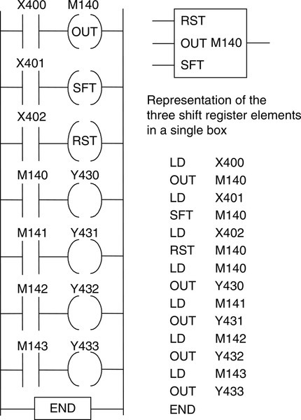
Figure 11.3 shows a shift register ladder program for a Toshiba PLC. With the Toshiba, R016 is the address of the first relay in the register. The (08) indicates that there are eight such relays. D is used for the data input, S for shift input, E for enable or reset input, and Q for output.
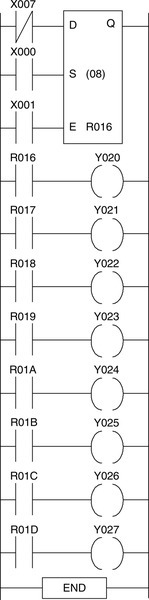
Figure 11.4 shows the IEC 61131-3 standard symbol for a shift register. The value to be shifted is at input IN and the number of places it is to be shifted is at input N.
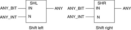
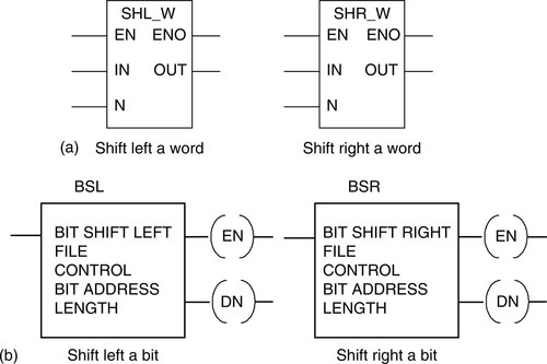
Figure 11.5a shows the Siemens symbol for a shift register. If the enable input EN is 1, the shift function is executed and ENO is then 1. If EN is 0, the shift function is not executed and ENO is 0. The shift function SHL_W shifts the contents of the word variable at input IN bit by bit to the left the number of positions specified by the input at N. The shifted word output is at OUT. Figure 11.5b shows the Allen-Bradley PLC 5 and SLC 500 symbols for shift registers. The FILE gives the address of the bit array that is to be shifted. CONTROL gives the address of control bits such as bit 15 (EN) as a 1 when the instruction is enabled, bit 13 (DN) as a 1 when the bits have shifted, and bit 11 (ER) as a 1 when the length is negative, and bit 10 (UL) stores the state of the bit that was shifted out of the range of bits. BIT ADDRESS is the address of the data to be shifted. LENGTH is the number of bits in the array to be shifted.
11.2.1 A Sequencing Application
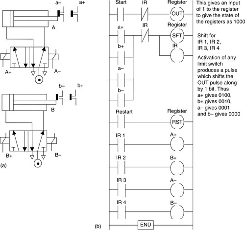
Consider the requirement for a program for two double-solenoid cylinders, the arrangement as shown in Figure 11.6a, to give the sequence A+, B+, A–, B–. Figure 11.6b shows a program to achieve this sequence by the use of a shift register.
11.2.2 Keeping Track of Items
The preceding indicates how a shift register can be used for sequencing. Another application is to keep track of items. For example, a sensor might be used to detect faulty items moving along a conveyor and keep track of them so that when they reach the appropriate point, a reject mechanism is activated to remove them from the conveyor. Figure 11.7 illustrates this arrangement and the type of ladder program that might be used.
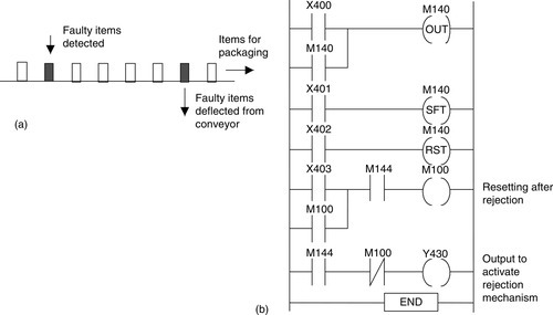
Each time a faulty item is detected, a pulse signal occurs at input X400. This enters a 1 into the shift register at internal relay M140. When items move, whether faulty or not, there is a pulse input at X401. This shifts the 1 along the register. When the 1 reaches internal relay M144, it activates the output Y430 and the rejection mechanism removes the faulty item from the conveyor. When an item is removed, it is sensed and an input to X403 occurs. This is used to reset the mechanism so that no further items are rejected until the rejection signal reaches M144. It does this by giving an output to internal relay M100, which latches the X403 input and switches the rejection output Y430 off. This represents just the basic elements of a system. A practical system would include further internal relays to make certain that the rejection mechanism is off when good items move along the conveyor belt as well as to disable the input from X400 when the shifting is occurring.
Summary
The term register is used for an electronic device in which data can be stored. The shift register is a number of internal relays grouped together that allow stored bits to be shifted from one relay to another. With the shift register it is possible to shift stored bits. Shift registers require three inputs: one to load data into the first location of the register, one as the command to shift data along by one location, and one to reset or clear the register of data. The grouping together of internal relays to form a shift register is done automatically by a PLC when the shift register function is selected.
Problems
Problems 1 through 9 have four answer options: A, B, C, or D. Choose the correct answer from the answer options. Problems 1 through 5 concern a 4-bit shift register involving internal relays IR 1, IR 2, IR 3, and IR 4, which has been reset to 0, 0, 0, 0.
1. When there is a pulse 1 input to the OUT of the shift register, the internal relays in the shift register show:
B. 0010
C. 0100
D. 1000
2. Following a pulse input of 1 to the OUT of the shift register, there is a pulse input to SHIFT. The internal relays then show:
B. 0010
C. 0100
D. 1000
3. With a continuous input of 1 to the OUT of the shift register, there is a pulse input to SHIFT. The internal relays then show:
B. 0110
C. 1100
D. 0010
4. With a continuous input of 1 to the OUT of the shift register, there are two pulse inputs to SHIFT. The internal relays then show:
B. 0010
C. 1100
D. 1110
5. With a pulse input of 1 to the OUT of the shift register, there is a pulse input to SHIFT, followed by a pulse input to RESET. The internal relays then show:
B. 0010
C. 0100
D. 1000
Problems 6 through 9 concern Figure 11.8, which shows a 4-bit shift register with internal relays IR 1, IR 2, IR 3, and IR 4, with three inputs (In 1, In 2, and In 3) and four outputs (Out 1, Out 2, Out 3, and Out 4).
6. Decide whether each of these statements is true (T) or false (F). When there is a pulse input to In 1:
(i) The output Out 1 is energized.
(ii) The contacts of internal relay IR 1 close.
A. (i) T (ii) T
B. (i) T (ii) F
C. (i) F (ii) T
D. (i) F (ii) F
7. Decide whether each of these statements is true (T) or false (F). When there is a pulse input to In 1 followed by a pulse input to SFT:
(i) Output Out 1 is energized.
(ii) Output Out 2 is energized.
A. (i) T (ii) T
B. (i) T (ii) F
C. (i) F (ii) T
D. (i) F (ii) F
8. Decide whether each of these statements is true (T) or false (F). To obtain outputs Out 1, Out 2, Out 3, and Out 4 switching on in sequence and remaining on, we can have for inputs:
(i) A pulse input to In 1 followed by three pulse inputs to SFT.
(ii) A continuous input to In 1 followed by three pulse inputs to SFT.
A. (i) T (ii) T
B. (i) T (ii) F
C. (i) F (ii) T
D. (i) F (ii) F
9. Initially: Out 1 off, Out 2 off, Out 3 off, Out 4 off
Next: Out 1 on, Out 2 off, Out 3 off, Out 4 off
Next: Out 1 off, Out 2 on, Out 3 off, Out 4 off
Next: Out 1 on, Out 2 off, Out 3 on, Out 4 off
The inputs required to obtain the preceding sequence are:
A. Pulse input to In 1 followed by pulse input to In 2.
B. Pulse input to In 1 followed by two pulses to In 2.
C. Pulse input to In 1 followed by pulse input to In 2, then by pulse input to In 1.
D. Pulse input to In 1 followed by pulse input to In 2, then by pulse inputs to In 1 and In 2.
10. Devise ladder programs for systems to carry out the following tasks:
(a) A sequence of four outputs such that output 1 is switched on when the first event is detected and remains on, output 2 is switched on when the second event is detected and remains on, output 3 is switched on when the third event is detected and remains on, output 4 is switched on when the fourth event is detected and remains on, and all outputs are switched off when one particular input signal occurs.
(b) Control of a paint sprayer in a booth through which items pass on an overhead conveyor so that the paint is switched on when a part is in front of the paint gun and off when there is no part. The items are suspended from the overhead conveyor by hooks; not every hook has an item suspended from it.
Lookup Tasks
11. Find out the details of shift registers available with PLCs from a particular range from a specific manufacturer.