Symbols
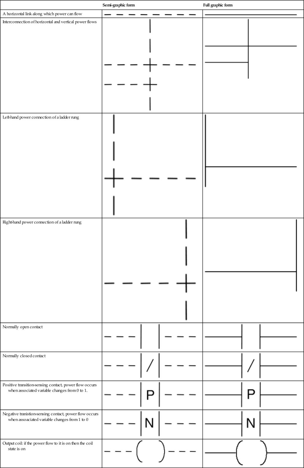
Ladder Programs
| Semi-graphic form | Full graphic form | |
| A horizontal link along which power can flow | ||
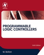
| Interconnection of horizontal and vertical power flows | 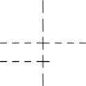 | 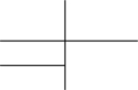 |
| Left-hand power connection of a ladder rung | 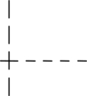 |  |
| Right-hand power connection of a ladder rung |  |  |
| Normally open contact | ||
| Normally closed contact | ||
| Positive transition-sensing contact, power flow occurs when associated variable changes from 0 to 1. | ||
| Negative tranistion-sensing contact, power flow occurs when assoaciated variable changes from 1 to 0 | ||
| Output coil: if the power flow to it is on then the coil state is on | ||
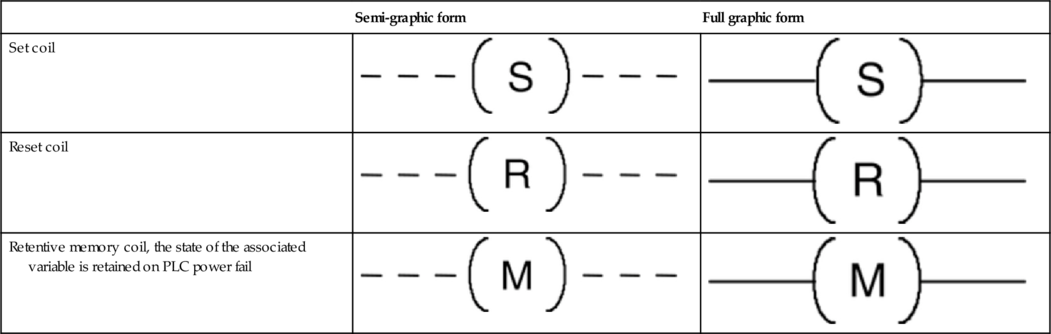
| Set coil | ||
| Reset coil | ||
| Retentive memory coil, the state of the associated variable is retained on PLC power fail |
Function Blocks
| Semi-graphic form | Full graphic form | |
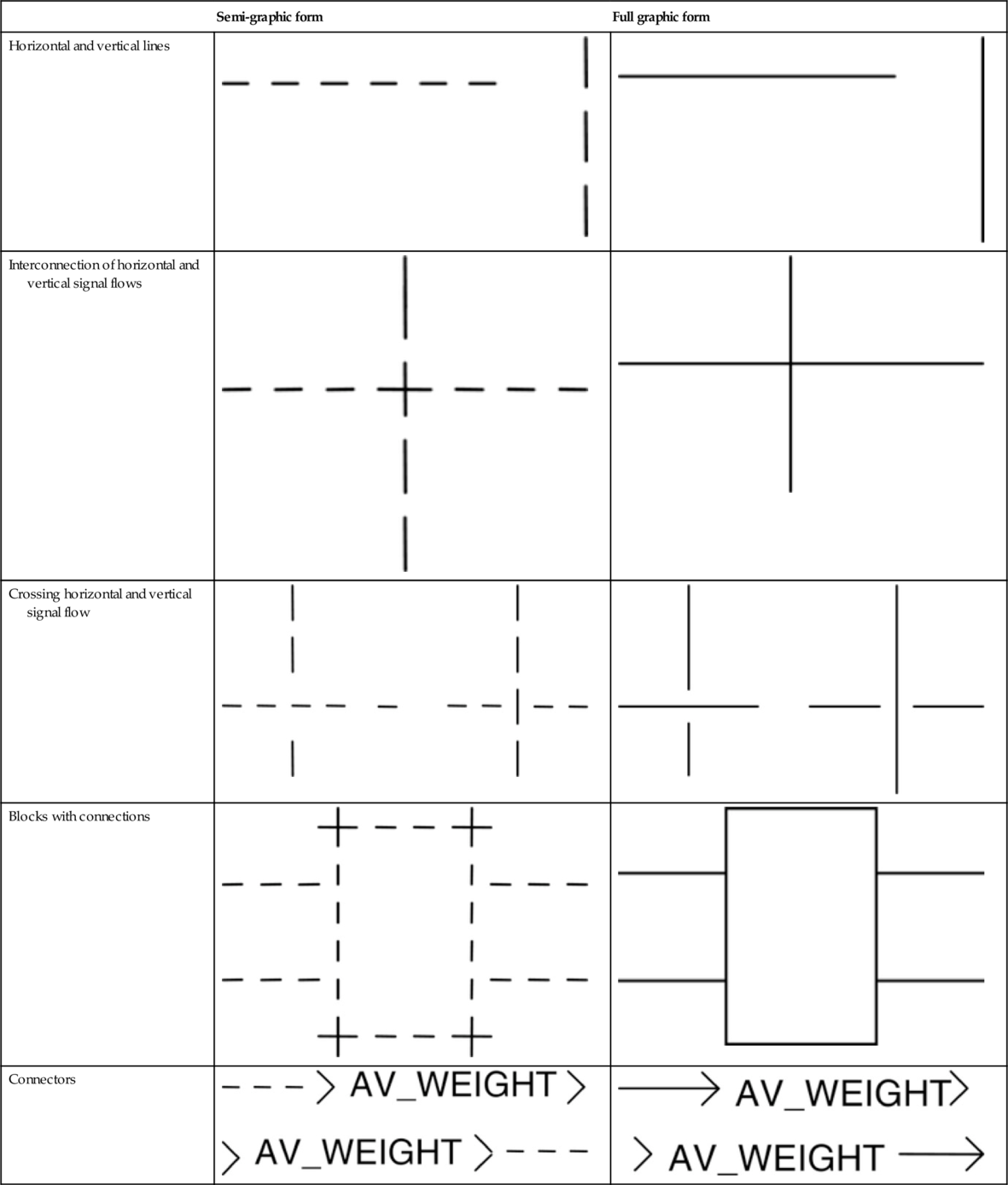
| Horizontal and vertical lines |  |  |
| Interconnection of horizontal and vertical signal flows | 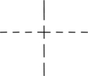 |  |
| Crossing horizontal and vertical signal flow |  | 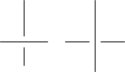 |
| Blocks with connections | 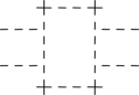 |  |
| Connectors |
Commonly Encountered Blocks
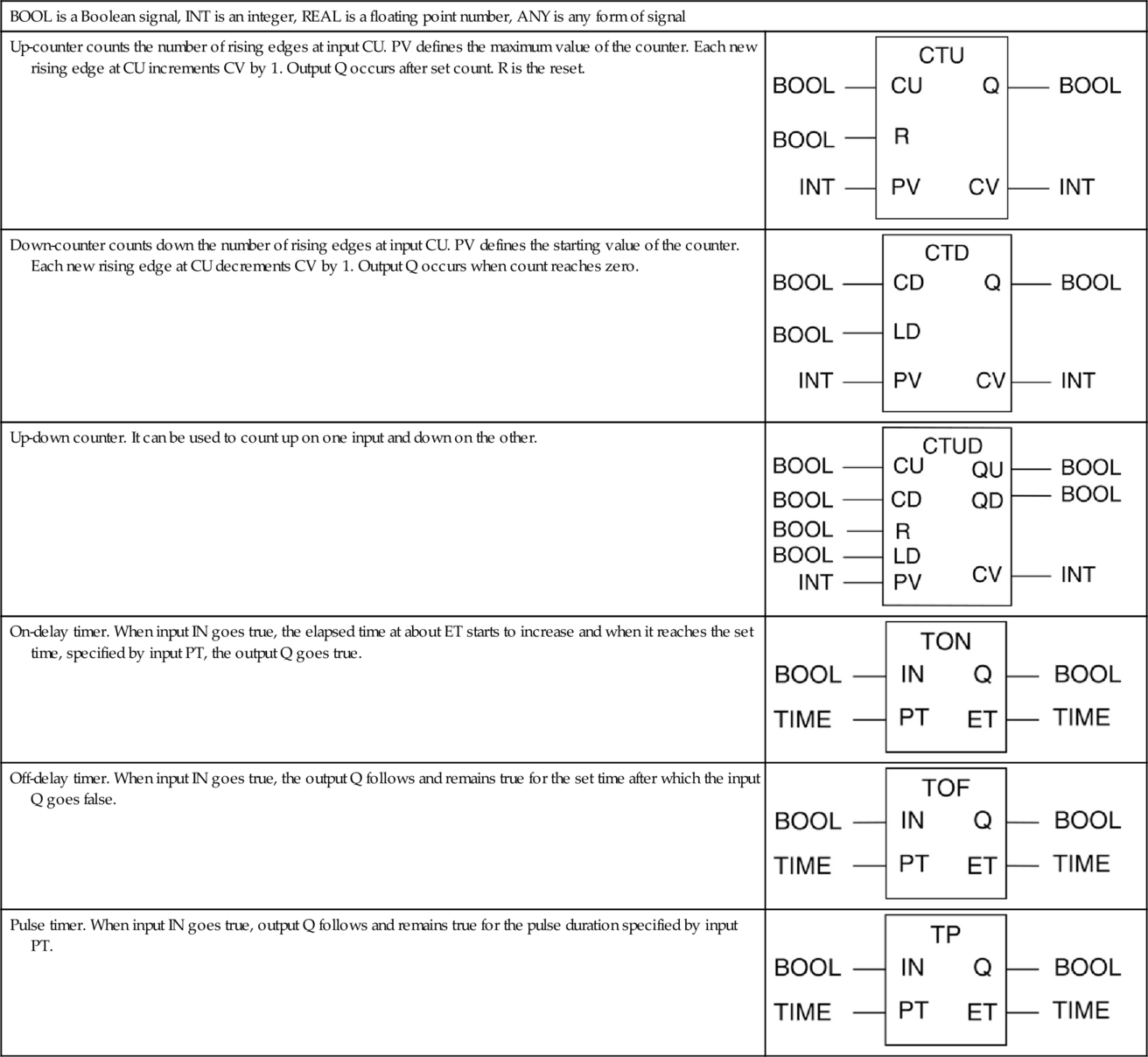
| BOOL is a Boolean signal, INT is an integer, REAL is a floating point number, ANY is any form of signal | |
| Up-counter counts the number of rising edges at input CU. PV defines the maximum value of the counter. Each new rising edge at CU increments CV by 1. Output Q occurs after set count. R is the reset. | 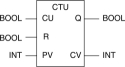 |
| Down-counter counts down the number of rising edges at input CU. PV defines the starting value of the counter. Each new rising edge at CU decrements CV by 1. Output Q occurs when count reaches zero. | 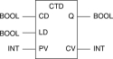 |
| Up-down counter. It can be used to count up on one input and down on the other. |  |
| On-delay timer. When input IN goes true, the elapsed time at about ET starts to increase and when it reaches the set time, specified by input PT, the output Q goes true. | |
| Off-delay timer. When input IN goes true, the output Q follows and remains true for the set time after which the input Q goes false. | |
| Pulse timer. When input IN goes true, output Q follows and remains true for the pulse duration specified by input PT. | |
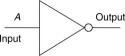
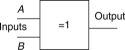
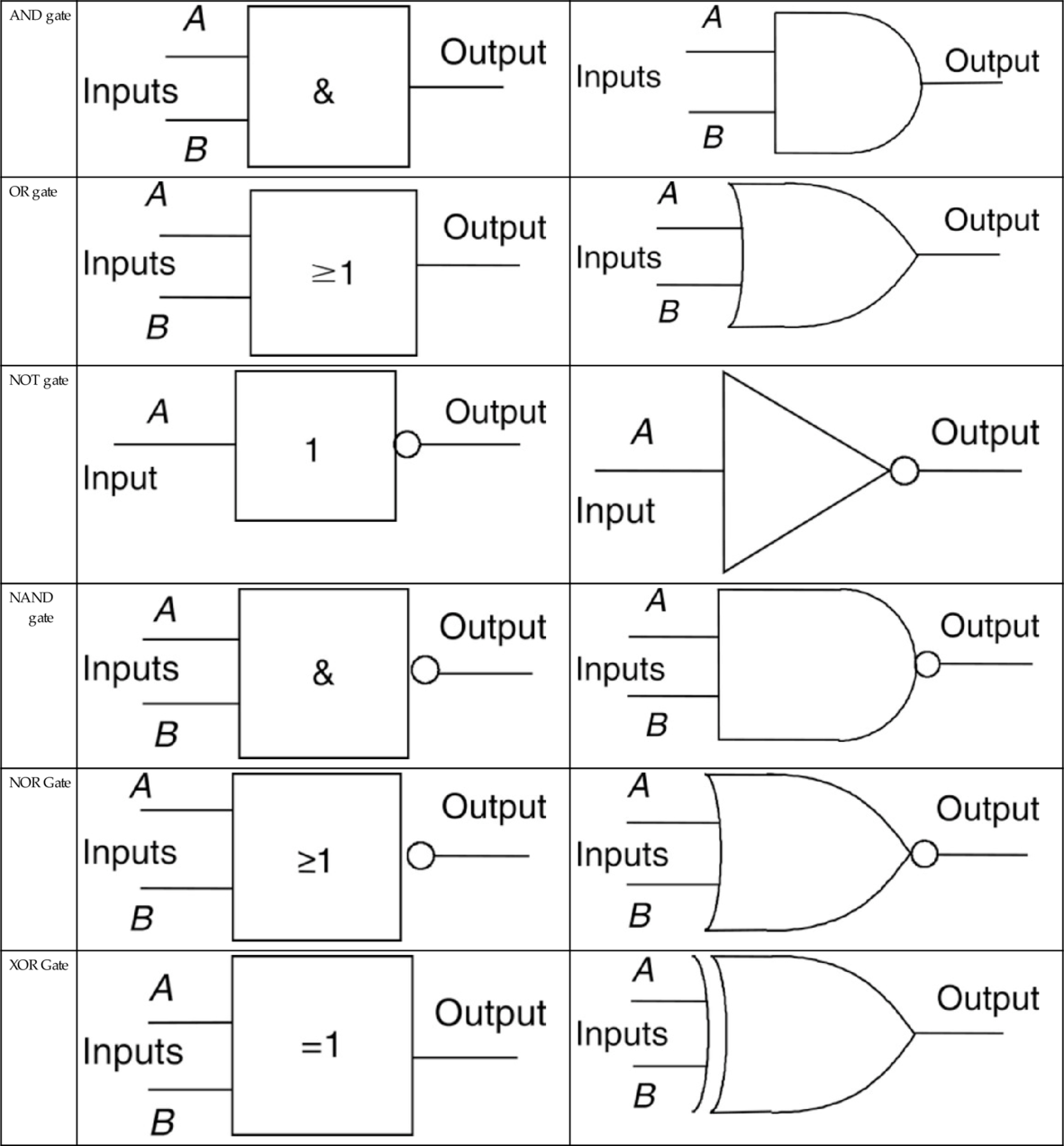
Logic Gates
Sequential Function Charts
| Start step. This defines the step which will be activated when the PLC is cold-started. | 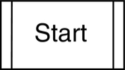 |
| Transition condition. Every transition must have a condition. One that always occurs should be shown with the condition TRUE. | |
| Step in a program | 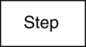 |
| Every step can have an associated action. An action describes the behavior that occurs when the step is activated. Each action can have a qualifier: N indicates the action is executed while the step is active. If no qualifier is indicated it is taken to be N. | |
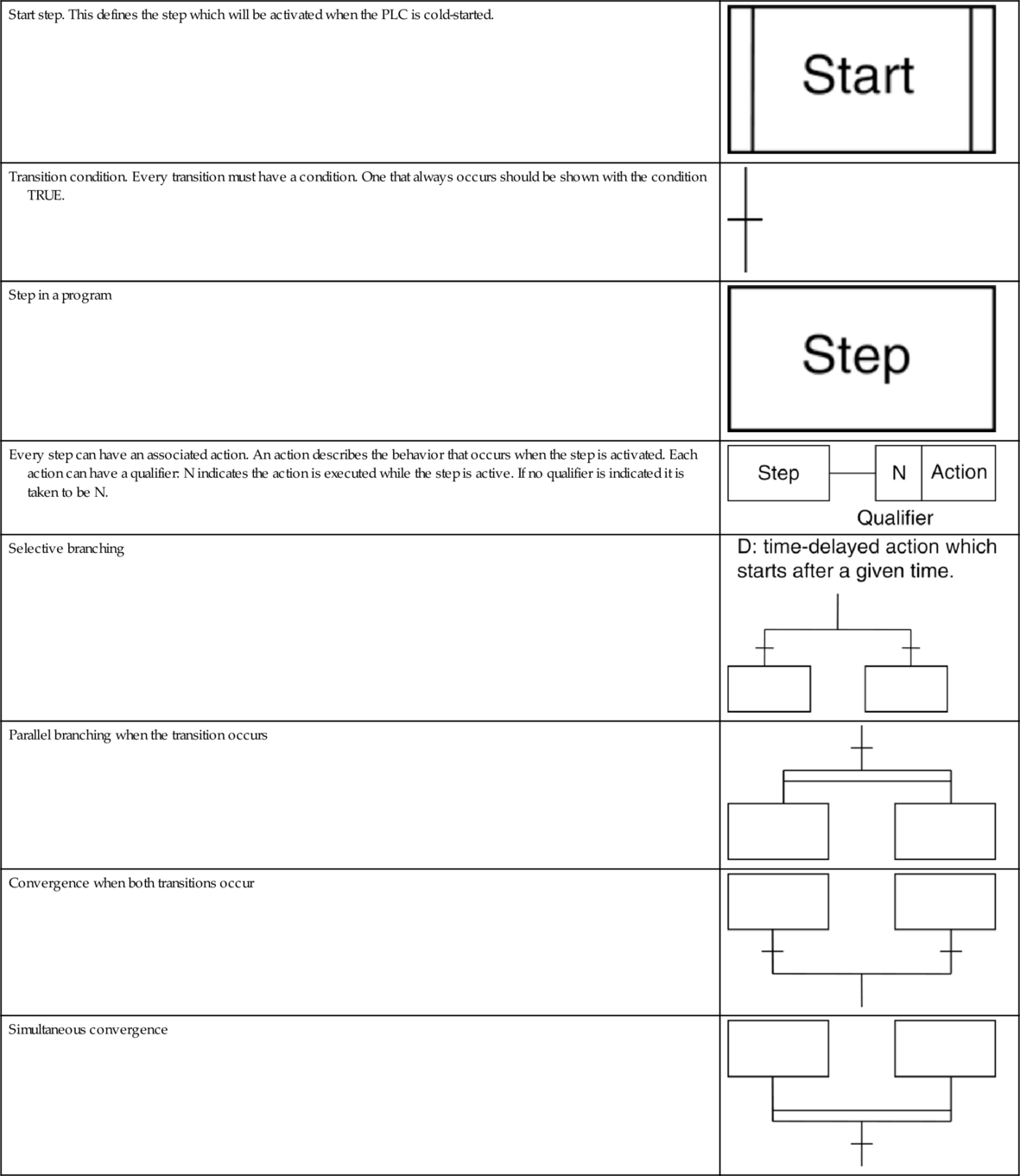
| Selective branching | 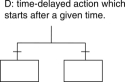 |
| Parallel branching when the transition occurs |  |
| Convergence when both transitions occur | 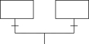 |
| Simultaneous convergence | 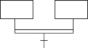 |
Instruction List (IEC 61131-3 Symbols)
LD Start a rung with an open contact
LDN Start a rung with a closed contact
ST An output
S Set true
R Reset false
AND Boolean AND
ANDN Boolean NAND
OR Boolean OR
ORN Boolean NOR
XOR Boolean XOR
NOT Boolean NOT
ADD Addition
SUB Subtraction
MUL Multiplication
DIV Division
Structured Text
X:= Y Y represents an expression that produces a new value for the variable X.
Operators
(…) Parenthesized (bracketed) expression
Function(…) List of parameters of a function
** Raising to a power
−, NOT Negation, Boolean NOT
*, /, MOD Multiplication, division, modulus operation
+, − Addition, subtraction
<, >, <=, >= Less than, greater than, less than or equal to, greater than or equal to
=, <> Equality, inequality
AND, & Boolean AND
XOR Boolean XOR
OR Boolean OR
Conditional and Iteration Statements
IF … THEN … ELSE is used when selected statements are to be executed when certain conditions occur.
The FOR … DO iteration statement allows a set of statements to be repeated, depending on the value of the iteration integer variable.
The WHILE … DO iteration statement allows one or more statements to be executed while a particular Boolean expression remains true.
The REPEAT … UNTIL iteration statement allows one or more statements to be executed and repeated while a particular Boolean expression remains true.