
7. Working with Relationships
Relationships Graphs and ERDs
Chapter 5, “Relational Database Design,” outlined some database theory that helps produce an ERD—an entity-relationship diagram that shows the fundamental building blocks of a database system and the ways in which they relate. In Chapter 6, “Working with Multiple Tables,” you saw how to use FileMaker’s relationship tools to turn an ERD into a working FileMaker database. This might mislead you into thinking that the Relationships Graph is really the same thing as an ERD, and that the relationships you build there match one-to-one with the relationships you sketch out on your ERD.
In fact, there’s a lot more to relationships in FileMaker. The Relationships Graph certainly handles all the structural relationships present on an ERD. But there are many other ways to use relationships in FileMaker. The ERD-based relationships are the structural core of any FileMaker database (or any relational database), but this chapter takes you beyond the core and shows you some other ways you can use relationships in FileMaker. It also delves further into the features of the Relationships Graph and discusses different ways of organizing files, tables, and table occurrences in a FileMaker system.
Like the preceding chapter, this chapter uses the Small Task Management database. You can download it from the author’s website as described in the Introduction. Although the name is the same as the database from Chapter 6, the downloadable database for this chapter incorporates the changes made here, so make certain that you look at the Chapter 7 version if you want to compare the downloadable database with the text of the chapter.
Relationships as Queries
Relationships can be more than classical database relationships in FileMaker Pro: They can be saved queries (something that does not exist in the world of SQL). In the Small Task Management database created in Chapter 6, you saw how to add a Tasks portal to the layout based on the Projects table.
The portal looks into the table of tasks and is based on the one-to-many relationship between a project and task set, based on a shared key called zzID in Projects and ProjectID in Tasks. But the portal also represents a kind of query, which says, “Show me all tasks for this project.”
Relationships are often (but not always) simple matches of key values, but queries typically involve many components. You can create a relationship that is a saved query that will, for example, display not only all the tasks for a project, but also those tasks for a project that have a due date before or after a given date.
The distinction between a relationship and a saved query in FileMaker is in the purposes for which you use them: All are FileMaker relationships.
The database as it is now contains the basic relationship of tasks for a project. To be able to create a new relationship to implement this query, we need to add a field to the database and then delve into three new concepts in FileMaker relationships:
• Nonequijoins
• Table occurrence
• Multiple match
The new field to add is a date field that you can use in the relationship as a cut-off date before or after which data will be included (or excluded) from the Tasks table. This new date field is added to Projects so that it can control the date-sensitive relationship from Projects to Tasks. Fields that control relationships such as this one are frequently global fields: There is no need to have a different value for each record. Create a global date field in Projects and call it gDateLimit.
Not using a global for this type of control field matters only if you want to allow multiple windows to be open using the same relationship at the same time and if you want each to be able to have its own control value.
Nonequijoins
In the Relationships Graphs shown in Chapter 6, all the relationships have a box with an equal sign in the middle of the line connecting the two table occurrences. To explore what that means, you can double-click that box to edit the relationship. Figure 7.1 shows the Edit Relationship dialog.
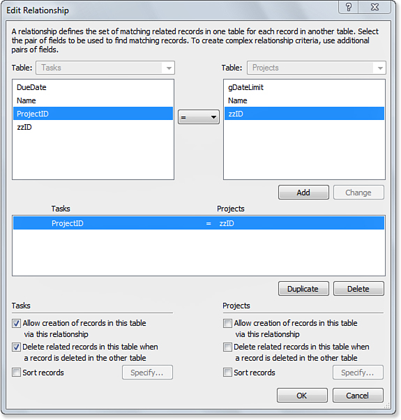
Figure 7.1. FileMaker can use any of seven different operators to compare match fields.
This relationship is built between a ProjectID in Tasks and a zzID in Projects. The match criterion is based on equality, meaning that records match (and hence are displayed in a portal that shows records from this relationship) if and only if the ProjectID in Tasks is exactly equal to the zzID in Projects. This is the correct behavior for the structural relationship represented on the ERD. Such a relationship, based on equality, is called an equijoin.
The upper part of the Edit Relationship dialog is the place where the match actually is defined. Notice, in Figure 7.1, that equality is not the only operator available for defining a match. In fact, you can build relationships based on combinations of any of the seven comparison operators.
To build the new relationship that implements the query showing you a project’s tasks that are due before or after gDateLimit, you need to build a nonequijoin relationship that uses < or > to match to the date field in Tasks. You could update the existing Relationships Graph to modify the relationship between Tasks and Projects, but it makes more sense to add a new relationship that implements this query while leaving the existing one intact because both relationships have useful but different purposes in the database.
Adding a Table Occurrence to the Relationships Graph
The Relationships Graph displays table occurrences and the relationships between them. A table occurrence is based on an actual table (that is, one that appears in the Tables tab of the Manage Database dialog or in an external data source), but it is not the table itself. When you create a new table in the Tables tab, a table occurrence with that name is added to the Relationships Graph, so it is easy to think that the occurrence is the table itself.
A single table can have multiple table occurrences in the Relationships Graph. Indeed, there are certain cases in which you need to do this. Paths in the Relationships Graph must be unambiguous. Consider the case of three tables with three table occurrences in a Relationships Graph: call them Table/table occurrence A, B, and C. If there is a relationship from A to B and another from B to C, you have established a path from A to C, and it is unambiguous.
Now add table and table occurrence D. You can create a relationship from A to D with no problem. But if you attempt to create a relationship from D to C, FileMaker Pro will not let you. To do so would create a second path from A to C using the A-to-D relationship and the D-to-C relationship. The criteria for the intermediate relationships almost certainly will be different, so if you traverse the A-B-C path, the specific data you retrieve will be different than if you traverse the A-D-C path.
The solution is to create a new table occurrence based on C. Call it C2 for the moment. Now you have two unambiguous paths from table A to table C. One goes through the table occurrences A-B-C, and the other goes through the table occurrences A-D-C2. In both cases, you can access data from table C from table A, but by using distinct paths, you can control the relationships that are used.
In the current example, you want a new view of Tasks from the perspective of Projects based on a nonequijoin match of dates. Therefore, you need to add a new occurrence of the Tasks table to the Graph. (All the existing table occurrences were automatically added when you created the underlying tables.) To add the new table occurrence of Tasks, open the Relationships Graph in the Manage Database dialog and click the Add Table Occurrence icon in the lower-left corner (it is the leftmost icon in the bottom row). Figure 7.2 shows the resulting Specify Table dialog.
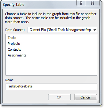
Figure 7.2. You can add a new table occurrence to the Relationships Graph.
In the Specify Table dialog, choose a source table to include in the Graph. In this case, you want to add another occurrence of Tasks. At the bottom of the box is a place for you to name the table occurrence. Because the original occurrence of the Tasks table is already named Tasks, you need a new name. FileMaker automatically generates a name with a number added to the last occurrence name. We recommend a name that says something about the way the new relationship will be used. In this case, TasksBeforeDate fits the bill. Figure 7.3 shows the Relationships Graph with the new table occurrence, as well as the gDateLimit field you added to Projects.
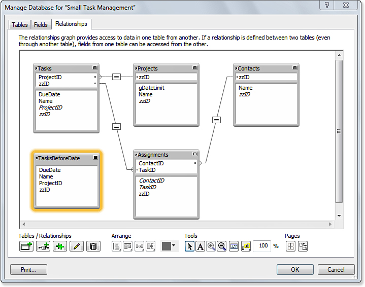
Figure 7.3. A second occurrence of the Tasks table has been added to the Graph.
All that’s left is to create a relationship from Projects to this new table occurrence, which will incorporate the gDateLimit field into the match criteria.
Defining a Relationship with Multiple Match Criteria
Chapter 6 showed you how to define new relationships in the Relationships Graph with a graphical technique consisting of dragging from one match field to another. In addition, you can add a new relationship simply by clicking the small Add Relationship icon (the second icon in the Tables/Relationships icon group at the lower left of the Relationships Graph, as shown in Figure 7.3). Clicking that icon brings you the familiar Edit Relationship dialog, but it’s initially completely empty.
Begin by selecting the two tables that are to participate in the relationship. Draw the relationship between Projects and TasksBeforeDate. It doesn’t matter which direction you draw the relationship, but you need to notice which table is on which side in the Edit Relationship dialog. Define the first match criterion. Select the ProjectID field from TasksBeforeDate and the zzID field from Projects, make sure that the menu of operators in the middle shows an equal sign, and click the Add button. So far it looks exactly like the Edit Relationship screen for the original Projects-Tasks relationship that was shown in Figure 7.1, except that the table occurrence on the left is now TasksBeforeDate instead of Tasks.
But you still need to tell FileMaker to consider only those Tasks on which the due date is before the cut-off date in the gDateLimit field. To make this happen, you add another criterion to the relationship. Select gDateLimit on the right in Projects, DueDate on the left in TasksBeforeDate, and from the operator menu in the middle, select the < sign. Click Add, and the new match criterion is added in the middlemost box, as shown in Figure 7.4.
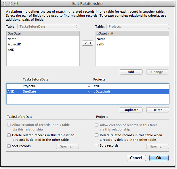
Figure 7.4. Using a nonequality condition to build a relationship.
Notice what that middle box is saying now. There’s a large AND in the left margin, which says that this relationship pulls only those tasks for which the project ID matches AND the due date is before the cut-off date.
Relationships in the Relationships Graph are bidirectional; you can access one table occurrence from the other side. This does not matter with equijoins. However, with nonequijoins, you must make certain that the logic recognizes which table is on which side. In this case, because the cut-off date is in Projects on the right, the operator to select due dates for Tasks (on the left) must be <. If TasksBeforeDate were on the right, the operator to select due dates would be >. Both relationships would enforce the same logic.
You might be wondering how to create a multiple-match relationship that works if any one of the criteria is true, as opposed to those that work only if all the criteria are true. This isn’t possible, unfortunately. To learn more, see “No OR Conditions with Multiple Match Criteria” in the “Troubleshooting” section near the end of this chapter.
Notice also how FileMaker represents this new relationship in the Relationships Graph. Each end of the relationship line forks to indicate the multiple match criteria—and the operator symbol in the middle of the line is a curious kind of X, indicating a complex match with multiple operators at work. Figure 7.5 shows the Relationships Graph with the new relationship.
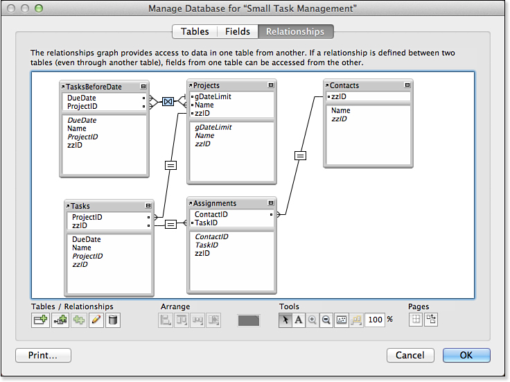
Figure 7.5. The Relationships Graph indicates when a relationship is based on multiple match fields. The [X] comparison operator shows that multiple operators are in use as well.
To use the new relationship, you could draw another portal on the Projects layout. Base it on TasksBeforeDate instead of plain Tasks, and use the same data fields. The result should be similar to what you see in Figure 7.6. When you simply change the date, different data is automatically displayed. (You use the Projects layout on the base because that is the place where the gDateLimit field is located; the portal is to TasksBeforeDate.)
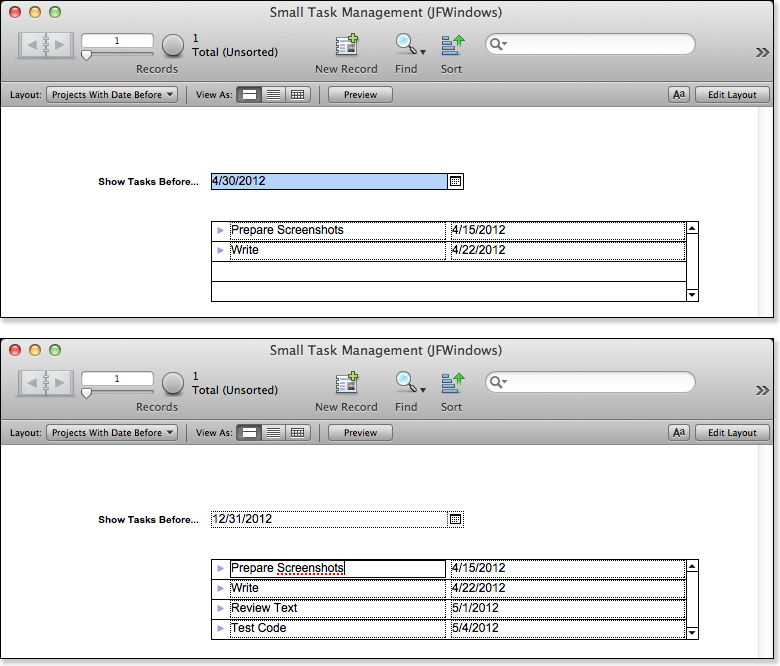
Figure 7.6. More complex relationships can produce sophisticated views, such as the TasksBeforeDate view shown here, which uses a portal onto the complex relationship as well as the FileMaker Pro drop-down calendar interface elements.
You can also duplicate the existing Projects layout, rename it, and double-click the portal to change its source from Tasks to TasksBeforeDate. Remember to double-click the fields in the portal to also change their source from Tasks to TasksBeforeDate. That is the method used in the downloadable example.
To add a comparable TasksAfterDate relationship, you can repeat the steps in this section; just reverse the direction of the relationship operator (in other words, the cut-off date will be before the task due dates).
In designing an interface like this, you have to decide how to handle exact matches. If you use less than or equal or greater than or equal, you will display exact matches to the cut-off date in both portals, which could be misleading. You can add a third portal that displays the exact date’s events, or, provided that you clarify this in the interface, you can choose a combination of less than or equal and greater than (or the reverse) so that exact match dates appear in only one place or the other.
These three concepts—nonequijoins, multiple table occurrences, and multiple match criteria—afford you extraordinary flexibility as a database developer. The sections ahead explore examples that show how to use these tools to solve particular problems of database design.
Creating Self-Relationships
In the preceding section, you created a relationship controlled by a date in the Projects table to display related data from Tasks. You can use the same logic to relate one occurrence of the Tasks table to another occurrence of the Tasks table so that you can see tasks due before a given task.
The basic process is the same: You select a field in the controlling table (which is a Tasks occurrence, such as the original Tasks table), and you implement the relationship to a new table occurrence, which drives a portal that is displayed in the window of the basic Tasks occurrence. You do not even have to add another date field. You can use this mechanism to display the tasks due before the date of a given task in the same project. This section shows you how to do that.
First, create a new table occurrence based on the Tasks table called TasksBeforeThisTask using the same technique illustrated previously in Figure 7.2.
Then, instead of creating a relationship to Projects, you can create a relationship between the new occurrence, TasksBeforeThisTask, and the original Tasks occurrence. Figure 7.7 shows that relationship.
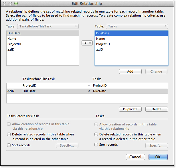
Figure 7.7. Create a self-join relationship.
Both occurrences are based on the Tasks table, so the fields are the same. Match the DueDate field of Tasks to DueDate in the new occurrence so that DueDate in Tasks is greater than DueDate in the new occurrence (or vice versa—it doesn’t matter as long as you are consistent in your naming). You also need to match the ProjectID in both Tasks records so that you are including only peer tasks with the same Project ID.
This is the same logic you applied in the preceding section, and you can now update the Tasks layout so that it displays data for a Tasks record at the top and displays a TasksBeforeThisTask portal below, as shown in Figure 7.8. As you page through tasks, you will see that the portal is always updated to show peer tasks on the project with due dates before the current task’s due date.
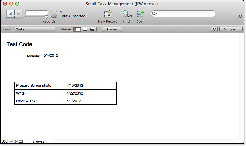
Figure 7.8. Display the self-join.
Creating a Relationship with a Global Value
You have seen how to implement the Project-Tasks relationship where a global date field controls the selected Tasks records. (Remember that you have to take into account the issues of multiple windows in deciding whether to use a global field.)
You can also use a constant global value, one that is not entered dynamically by the user, to implement a relationship.
An obvious candidate for such a relationship is a modification to the preceding self-join. You can add a third component to the join so that you select peer projects (that is, those with the same Project ID), due dates before the given task’s due date, and a new field—status—equal to a global status value. To implement this, you add two fields to the Tasks table: Status and gStatus. One is the status of the task, and the other is a global value that contains a status value from the status value list.
You can build on the relationship between Tasks and TasksBeforeThisTask to incorporate the new status field. The clause that you want to add is a match in which Status in TasksBeforeThisTask matches gStatus.
![]() For more details on globals in a multiuser environment, see Chapter 19, “Debugging and Troubleshooting.”
For more details on globals in a multiuser environment, see Chapter 19, “Debugging and Troubleshooting.”
Figure 7.9 shows the completed relationship. One additional feature has been added: The zzID field on both sides must not match. This is one way of resolving the issue noted previously in which a greater than or equal (or less than or equal) operator can include the base task itself in the list of related tasks. This prevents the task from being related to itself.
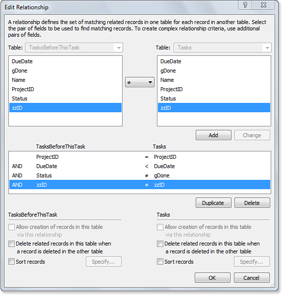
Figure 7.9. Enhance the relationship.
As always, when you add fields to the Tasks table, you will notice that the Relationships Graph is automatically updated so that all table occurrences display the new fields.
If you create a Status value list, you can add a set of radio buttons to the Task layout (see Figure 7.10); if that layout or another one displays related tasks (such as TasksBeforeThisTask described in the preceding section), you can add the status field to the portal.
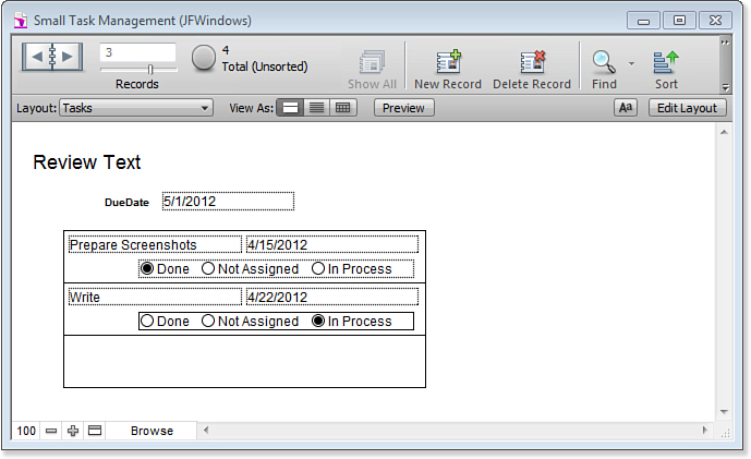
Figure 7.10. Finish up the layout.
This relationship, whether implemented between two tables or as a self-join, demonstrates the basics of a vast number of queries that you can implement in FileMaker Pro as relationships. One of the virtues of implementing queries as relationships is that they are always there: The logic is supplied in the relationship, and you do not have to worry about implementing find requests. Everything that you can implement in the database—be it in the Relationships Graph, in validation rules, or with auto-entry of data—represents something that does not have to be implemented in the scripts and interface or with user commands. That means after it is done, it is there and correct for all uses.
Self-joins come into play whenever you want to relate like objects. For example, you can use them to implement hierarchies such as employment structures in which each employee has a manager, who in turn has a manager.
Creating Cross-Product Relationships
In working with nonequijoin relationship matches, you might have noticed one oddball operator in the little menu of match criteria. Most of them are familiar comparison operators—but what about the last one, the one that looks like a ×?
That operator is known as a cross product (or Cartesian product). The cross product provides a “universal match” between the records in two tables. This means that it does no limiting of any kind. If you think of a relationship again as a kind of query, a cross-product relationship is a “find all” query. If you define a cross-product relationship from Projects to Tasks, a portal based on that relationship would always show all Tasks, no matter which Project record was being viewed. The choice of fields on the left and right sides is more or less unimportant; this “all to all” relationship is fulfilled regardless of the choice of match fields.
Cross products really make sense only by themselves, in single-match relationships. They have no effect at all if they’re added into multimatch criteria sets. A cross-product match condition is always true, so it can never further limit the potential matches of other criteria.
The cross product is the ultimate nonstructural relationship. After all, its purpose is to show all of something. These are generally used for various user-interface purposes. Sometimes you might want users to pick from a list of things, for example, and it’s more pleasing to allow them to pick from a scrolling list in a portal than from a drop-down list or menu. Generally, such techniques need to be coupled with some scripting to react to users’ choices.
Working with Multiple Files
In all the discussions of multitable systems in Chapters 5 and 6 and so far in this chapter, we’ve assumed that all the tables you want to work with live within a single FileMaker file. The capability to have many tables in a single physical file is, after all, one of the more convenient features of FileMaker. But there are still many reasons to build systems that are multifile, in addition to being multitable. This and the following sections review the mechanics of working with several files at once and then discuss different design strategies that use a multifile structure.
So far we’ve looked just at relationships between tables within the same file. But it’s also possible to build relationships between tables in different files. A very common situation arises when you are building a solution that uses data from an existing FileMaker database. In the case of the example used in this chapter, perhaps the Contacts table already exists in its own database file.
To reference the Contacts table in another file from your file, you only need create an external data source that uses the other file. You can then use that external data source to create new table occurrences for those tables. The data remains in the external file, but you can access it through the file references.
![]() The use of external data sources lets you use other FileMaker database files. You can also reference external databases using SQL and ODBC, as described in Chapter 21, “Connecting to External SQL Data Sources.”
The use of external data sources lets you use other FileMaker database files. You can also reference external databases using SQL and ODBC, as described in Chapter 21, “Connecting to External SQL Data Sources.”
Creating an External Data Source
External data sources are an extremely important topic in FileMaker. In a number of places in FileMaker, you might want to refer to or work with another file. Here are some of the things you can do with other files in FileMaker:
• Call a script in the other file.
• Use a value list defined in the other file.
• Refer to one or more tables from the other file in your Relationships Graph.
To do any of these things, you must first create a reference to the other file using an external data source. A file reference simply tells FileMaker where and how to find another file. FileMaker is capable of working with external files present on a local hard drive, present on a shared network volume, or present on an available FileMaker server. You can also specify multiple search locations for a file, and the priority in which they should be searched. You can, for instance, create a file reference that says, “First search for the file on the FileMaker server at 192.168.100.2. If you don’t find it there, look on the FileMaker server at 10.11.1.5. If you don’t find it there, give up or go on to these locations...”
Before FileMaker 7, versions kept track of these references behind the scenes and didn’t let you alter the order in which FileMaker searched for a given file. Problems with file references were harder to spot in previous versions and could occasionally give rise to a problem called crosstalk, in which the wrong copies of files could be accessed by mistake.
Since FileMaker 7, each physical file maintains its own list of file references. You can work with these references centrally and create them on the fly as needed. Let’s see how this works in practice.
Your first step is to define an external data source that will contain a file reference to the external file. To do this, choose File, Manage, External Data Sources. Click the New button on the next screen, and you see the Manage External Data Sources dialog, as shown in Figure 7.11.
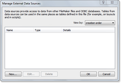
Figure 7.11. Add external data sources to a FileMaker database file.
When you click New or select an existing data source and click Edit, the dialog shown in Figure 7.12 opens. You can name the data source and select whether it is an external FileMaker file or one accessed via ODBC.
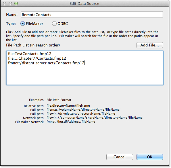
Figure 7.12. Edit the external data sources.
![]() Additional information on working with external FileMaker files is included in Chapter 21, “Connecting to External SQL Data Sources.”
Additional information on working with external FileMaker files is included in Chapter 21, “Connecting to External SQL Data Sources.”
Then you provide the actual file references for the data source. You can type in the path to the file that you want to use, or you can click Add File to use the standard Open File dialog to select the file from your local hard disk or the network. As you can see in Figure 7.12, you can provide several file references. FileMaker will search them in order until it finds a file to use.
In general, all the different file paths in the path list point to the same file; that is, a file with the same name and contents. In theory, you could also use a single path list to point to a number of different files, indicating that the later ones should be used if the earlier ones can’t be found. You could perhaps use this feature to fall back to other versions of a file or system if necessary.
In Figure 7.12, you can see a reference to a file in the same folder as the database into which the file reference is created. Below that is a file reference to a file in a folder with a common parent folder as that of the database file. On the third line is a reference to a file accessed through FileMaker Server or FileMaker peer-to-peer networking. In that case, as is always true when you use the Open Remote command, you connect to a copy of FileMaker and through it to the database. The other syntax connects to the database using your own copy of FileMaker.
As you can see at the bottom of the dialog, there are different forms of the syntax for OS X and Windows. Because the file references are searched in order, you can vary them for your development process.
If none of the file references can be resolved, you get an error message.
If you inserted a local reference to the file to aid offline development, you need to remember to remove that reference later, or perhaps move it lower on the list. Otherwise, FileMaker continues to search your local drive first, which is probably not desirable.
File references are resolved as FileMaker needs to access the given file rather than when the database opens. That improves the efficiency of cases in which not all file references are used in a particular session of FileMaker. It also is the reason why resolving file references occasionally can provide some frustration. If you have a situation in which sometimes there is an error in your FileMaker solution but not always, it might be that a file reference is to blame and the apparent randomness of the error is caused by the sequence in which file references need to be resolved. Sometimes you can track down these intermittently appearing bugs by reviewing all the file references in your external data sources and verifying that they are correct. Trailing spaces at the end of the file references are a notorious source of error.
Adding an External Table to the Relationships Graph
After you create the file references in your external data sources list, you can add tables from these external files to your Relationships Graph. If you open the Relationships Graph and click the Add Table Occurrence icon, you’ll notice something we didn’t highlight before. In the resulting Specify Table dialog, a menu lets you choose which file you want to browse for table choices. This menu always includes the current file and any file references you defined using the techniques covered in the previous sections of this chapter. Figure 7.13 illustrates this point.
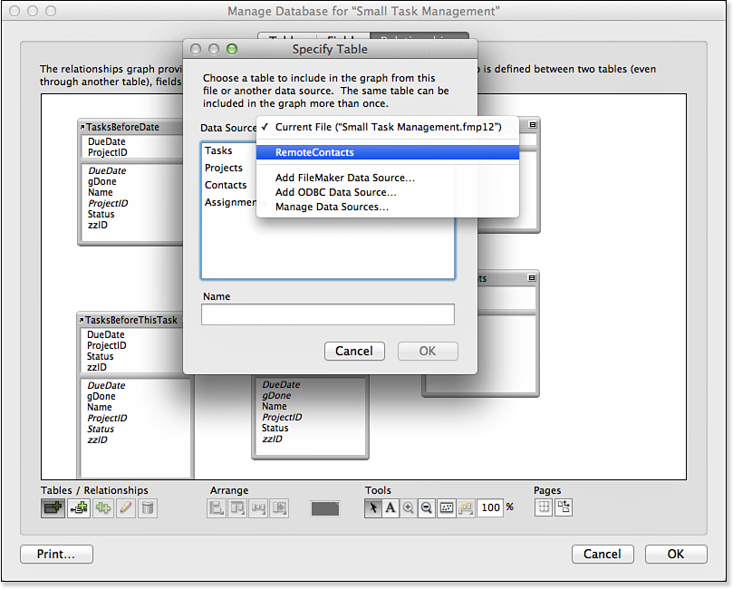
Figure 7.13. When adding a table occurrence to the Relationships Graph, you can base the new occurrence on a table in an external data source.
Because you name the external data source, you will see that name in the pop-up menu, as shown in Figure 7.13. Not only might you be accessing files in various locations, they may have different names, but the external data source name that appears in this dialog is what you work with.
The table is added to the Relationships Graph, much as all the other tables we’ve seen. The result is shown in Figure 7.14. There’s one subtle visual indication that the Contacts 2 table occurrence is based on a table from another file: The table occurrence name for Contacts 2 is italicized. In addition, if you hover the mouse pointer over the arrow in the upper left of the table, you can see the data source name. Otherwise, it’s just as though you were working with a table in the same file.
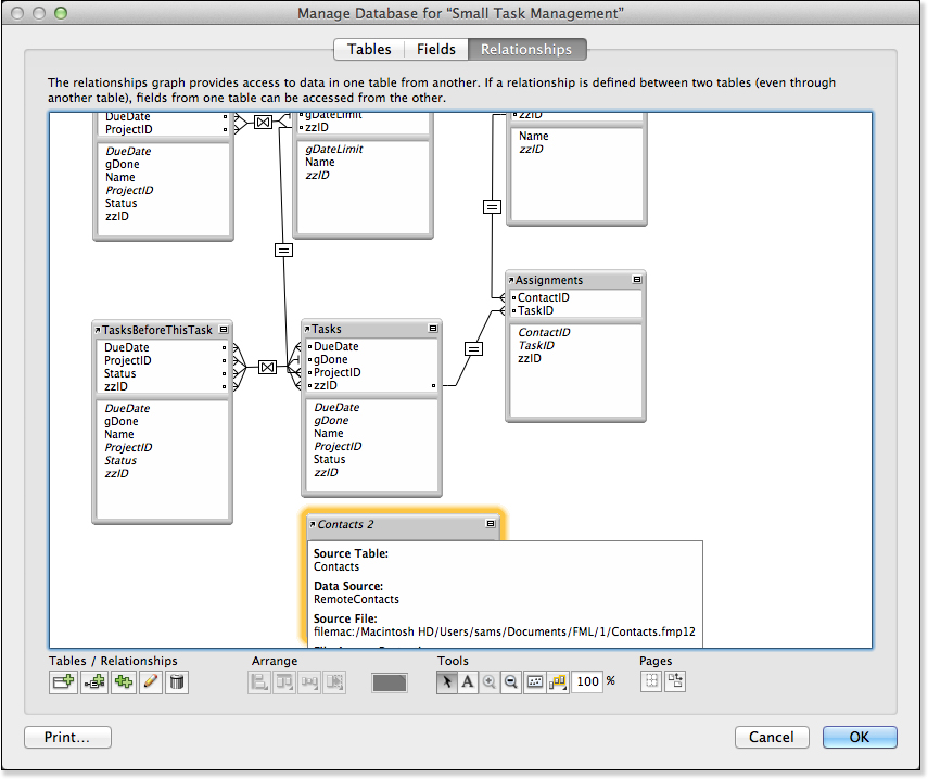
Figure 7.14. In this Relationships Graph, the italicized title of the Contacts 2 table occurrence shows that the source table exists in an external file.
Troubleshooting
Trouble Creating Related Records with Nonequijoins
I want to create a relationship that allows creation of related records on one side of the relationship, but the box that enables that capability is grayed out.
You might have noticed that the option Allow Creation of Records in This Table via This Relationship has mysteriously been disabled when a nonequijoin is part of the relationship. This suggests that you have one or more nonequality conditions in your relationship match criteria. The rule is this: FileMaker can allow the creation of related records only if the relationship in question consists only of conditions involving an equality comparison. This limits such relationships to using only the equal (=), less than or equal (≤), or greater than or equal (≥) operators.
Multiple match criteria are fine, as long as they’re all based on one of those three operators. This can actually be rather useful: A multimatch relationship that allows the creation of related records automatically fills in all the key fields of the related record. But as soon as any nonequality condition becomes involved in the match, the capability to create related records goes away.
This makes sense if you think about it. FileMaker can create a record via an equijoin because only one condition satisfies the match criteria for the current record. Suppose that you’re on a Customer Layout, looking at customer number 17, and you have a portal into Invoices, in which the relationship to Invoices is an equijoin on CustomerID. FileMaker can create a new record in the portal by creating a new invoice record and setting the CustomerID to 17. But suppose that the relationship instead were based on a “not equal to” relationship? To create a record on the other side, FileMaker would need to create an Invoice record with a customer ID other than 17. Fine, but what customer ID should it use? There’s really no way to say. Similar reasoning holds for other nonequijoin types: There’s no sensible way for FileMaker to decide what match data should go into the related record.
If the capability to create related records is enabled, the key fields in the related record will always be populated with values equal to the key field in the parent record, regardless of which of the three allowable relational operators is chosen. If you need to create related records where the relationship is not equality, you almost always do it with a script and, in many cases, that script is launched by a button that you place next to a portal.
No OR Conditions with Multiple Match Criteria
Whenever I add multiple match criteria to a relationship, FileMaker always tells me the match will work if condition 1 AND condition 2 AND condition 3 are true. But I have a match that needs to work if 1 OR 2 OR 3 is true. Where do I set that up?
You don’t, unfortunately. Using the native FileMaker relationship features, relational matches are always AND matches whenever multiple match criteria are specified. If you want to mimic the effect of an OR search in another table, you need to find another means of doing that. Say, for example, that you have a database with tables for teachers, classes, enrollments, and students. From the viewpoint of a teacher, you want to be able to view all students who are outside the norm—they have either a very low GPA or a very high GPA. You could try to do this with two match criteria, but that would necessarily be an AND match, which would never be fulfilled (no student would have both a low and a high GPA at once). The solution here would be to create a stored calculation in the student table called something like ExceptionalGPA, defined as follows:
If ( GPA < 2 or GPA > 3.75; 1; 0)
The calculation will have the value 1 when the student’s GPA is exceptionally high or low, and a value of 0 otherwise.
You could now create a field called Constant in the teacher table and define it as a calculation that evaluates to 1. Then specify a relationship between the teacher table and the student table, with multiple match criteria: TeacherID=TeacherID and Constant=ExceptionalGPA, meaning “Find me all students with the same teacher ID and an exceptional GPA.”
FileMaker Extra: Managing the Relationships Graph
The Relationships Graph in FileMaker is a nice answer to developers who clamored for years for a visual representation of relationships in FileMaker systems. But for large or complex systems, with many table occurrences, the Graph has the potential to be a bit unwieldy. Table occurrences in the Graph take up a fair amount of space, and it can be difficult to organize the occurrences without creating a web of overlapping relationship lines.
Using Formatting Tools to Manage the Relationships Graph
You can use a number of tools for Graph management. For one thing, the small “windowshade” icon at the upper right of a table occurrence can be used to hide the fields in the table occurrence, leaving only the match fields used in relationships. This can save valuable space. If you like to work from the keyboard, (![]() ) [Ctrl+T] will cycle through the various table occurrence display states (fully open, key fields only, fully closed). If you use (
) [Ctrl+T] will cycle through the various table occurrence display states (fully open, key fields only, fully closed). If you use (![]() ) [Ctrl+A] to select all objects in the Graph, you can windowshade your entire Graph with a few keystrokes.
) [Ctrl+A] to select all objects in the Graph, you can windowshade your entire Graph with a few keystrokes.
You can also manually resize an individual table occurrence to save space. This, again, needs to be done one table occurrence at a time. It’s also possible to zoom out from the Graph as a whole and view it at 75% or 50% of regular size, or smaller.
It might also be useful to you to organize your table occurrences into logical groups of some kind within the Relationships Graph. Let’s say you’re working on a trucking module with four table occurrences, and you also have a file reference to an external user-management module and you’ve used that to bring a number of user-oriented table occurrences into the Graph. FileMaker enables you to color-code table occurrences in the Graph, so it’s possible to give each group of table occurrences its own color.
You can add notes directly to the Graph. If you drag a rectangle in the Graph while holding (![]() -N) [Ctrl+N], you’ll create something like a sticky note. You can choose the color and typeface, and adjust the size and position. Notes appear behind other objects in the Graph.
-N) [Ctrl+N], you’ll create something like a sticky note. You can choose the color and typeface, and adjust the size and position. Notes appear behind other objects in the Graph.
While you are working, several keyboard shortcuts can make your life easier. Pressing (![]() -Y) [Ctrl+Y] will select all related table occurrences that are one step away from the current table occurrence. Pressing (
-Y) [Ctrl+Y] will select all related table occurrences that are one step away from the current table occurrence. Pressing (![]() -U) [Ctrl+U] will select all table occurrences with the same source table as the current table. Finally, you can use (
-U) [Ctrl+U] will select all table occurrences with the same source table as the current table. Finally, you can use (![]() -D) [Ctrl+D] to duplicate one or more selected table objects, as well as any relationships between them. This last point is a big convenience: You can select a complex group of related table occurrences and duplicate the entire cluster and its relationships at once. You can perform all these functions with the mouse by clicking new buttons that appear in the Relationships Graph.
-D) [Ctrl+D] to duplicate one or more selected table objects, as well as any relationships between them. This last point is a big convenience: You can select a complex group of related table occurrences and duplicate the entire cluster and its relationships at once. You can perform all these functions with the mouse by clicking new buttons that appear in the Relationships Graph.
Using Table Occurrences to Manage the Relationships Graph
As you have seen in this chapter, there must be unique paths between any two related table occurrences. A Customers table may be related to an Invoices table, which is in turn related to an Invoice Line Items table, which ultimately is related to Products. Thus, a path from Customers to Products exists.
If you want to track inquiries about products from a customer, you might have a path from Customers to Queries to Products. But that can’t be done, because now there are two paths between Customers and Products. The solution is to create a new table occurrence and name it something like ProductQueriesForCustomer. Even relatively small FileMaker solutions quickly wind up with special-purpose table occurrences of this sort. There is nothing wrong with this: It is just part of the development process.
Rather than creating duplicate table occurrences on an as-needed basis, many developers have begun to create them as part of the design process. Instead of a spider web of related and duplicative table occurrences, you can build smaller relationship sets that are tied into specific layouts and their purposes. Remember that a layout is always based on a primary table occurrence; from that table occurrence, related table occurrences can be shown in portals or individual fields. The set of table occurrences together with the layouts that use them form a logical group.
In the example described previously, you could create a Customer Query layout based on Queries. Right from the start, you can create new table occurrences such as Customers For Queries and Products For Queries. Relate both of those to Queries and use them in your Customer Query layout.
Now create a Customer Order Layout based on Orders. Again, create new table occurrences such as Customers for Orders, Order Line Items for Orders, and Products for Orders (or, more accurately, Products for Order Line Items).
Remember that you always have the option to display that related record in its own layout. Your layout choices consist of the layouts based on the underlying table (not the table occurrence). It is that particular feature that lets you “jump” from cluster to cluster.
This approach gives you more table occurrences in most cases, but the sections of your Relationships Graph are separate and easily understood. Each cluster will use its own table occurrences to support its own layouts. When you implement scripts or buttons to go to related records, you can go to a related record from the appropriate table occurrence.
![]() For more details on using table occurrences, see “
For more details on using table occurrences, see “Go to Related Record,” p. 478.