
6. Working with Multiple Tables
Multitable Systems in FileMaker Pro
This chapter shows you how to take the ideas from Chapter 5, “Relational Database Design,” and use them to build FileMaker database systems. You learn how to use FileMaker to create database systems that model the types of relationships covered in the preceding chapter.
Chapter 5 laid out a set of design concepts that centered around the ideas of entities, their attributes, and the relationships between entities. In FileMaker Pro, you generally represent a database entity (“student,” for example) as a table. You generally represent an entity’s attributes (“first name,” “year of graduation,” for example) by the fields of that table. And you create relationships among tables with FileMaker’s Relationships Graph.
The focus of this chapter is on implementing the relational model. Further chapters on layout design help you with additional interface features and modifications to the basic layout.
The sequence of steps involved in building a database solution such as this varies from person to person. Some people prefer to build the tables first and then add the fields and their options. Other people, knowing the basic fields used in each table, prefer to create a table with its fields and options and then move onto the next one. Do whatever makes most sense to you, realizing that FileMaker database development, more than most database development, is an iterative process. The only necessity is that to create a relationship in the Relationships Graph, you must have the two tables involved and the two fields that you want to use as the primary and foreign keys.
Creating a One-to-Many Relationship in FileMaker
In the Small Task Management database that you build in this chapter, there are going to be three basic tables (this is a multitable solution). Each table will have the five basic fields previously mentioned. Each is auto-entered by FileMaker Pro, and none can be modified by the user during data entry. To show the database structure more clearly in this chapter, only zzID is shown in the figures.
• zzID—This is the auto-entered serial number. Because it is auto-entered and unique, you can use it as the primary key of each record in each table of the database.
• zzCreator—This is the name of the creator of the record. It could be set to the account name if you prefer.
• zzModifier—This is the name of the last modifier of the record. It could be set to the account name if you prefer.
• zzCreationTS—This is the creation timestamp of the record.
• zzModificationTS—This is the last modification timestamp of the record.
If you are using FileMaker Pro Advanced, you can create a table with these fields and then copy and paste it for each new table you create. Alternatively, you can create the fields in a single table and copy and paste them into other tables.
These are the tables:
• Tasks—Each task has a name, a type of task, and a due date. Each task belongs to a single project.
• Projects—Each project has a name. It is related to zero or more tasks.
• Contacts—These are people or organizations who are assigned to tasks. Each contact can be assigned to zero or more tasks; each task can have zero or more contacts assigned to it.
Each entity in an entity-relationship diagram (ERD) generally translates into one table in a FileMaker system. The following sections describe how to begin.
Creating the First Table in a Multitable System
When you create a FileMaker database for the first time, you get a single table with the same name as the database file, along with a single layout that also has that name. If you create a new database called Small Task Management, you get within it a single table, also called Small Task Management.
By default, FileMaker Pro automatically switches to the spreadsheet-like table view shown in Figure 6.1. (You can change this in Preferences using the General tab and the “Use Manage Database dialog to create files” setting.)
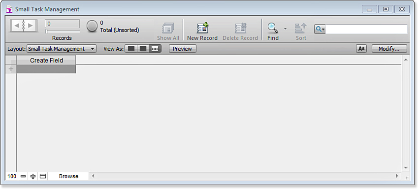
Figure 6.1. FileMaker Pro automatically creates your first table.
You create new fields by typing in the top row and entering the field name to replace Create Field. Press Tab. You will see that you now have a new field at the right that is named Field 2, as shown in Figure 6.2. If you use the Return key after entering a field name, you commit the name and stay in the same column (that is, no Field 2 is created).
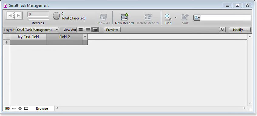
Figure 6.2. Create new fields.
When you click in a field title, a down-pointing arrow lets you choose field types and options, as shown in Figure 6.3.
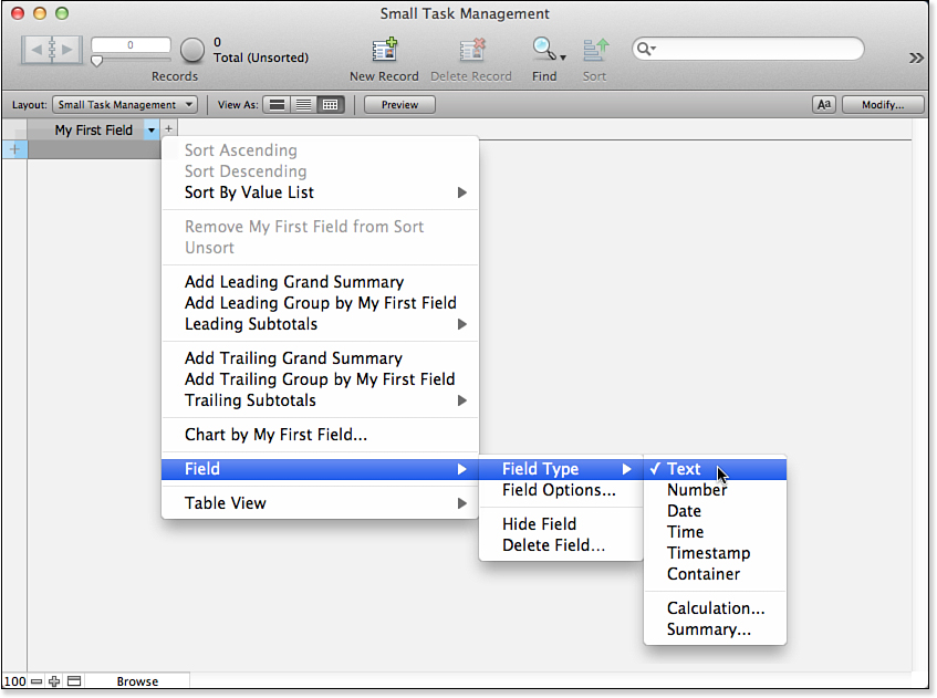
Figure 6.3. Set the field types and options.
You can also manage fields and tables from the Manage Database dialog found in the File, Manage submenu, as shown in Figure 6.4. The Manage Database dialog offers you more options. Use the table view or Manage Database dialog, depending on your preference at the time.
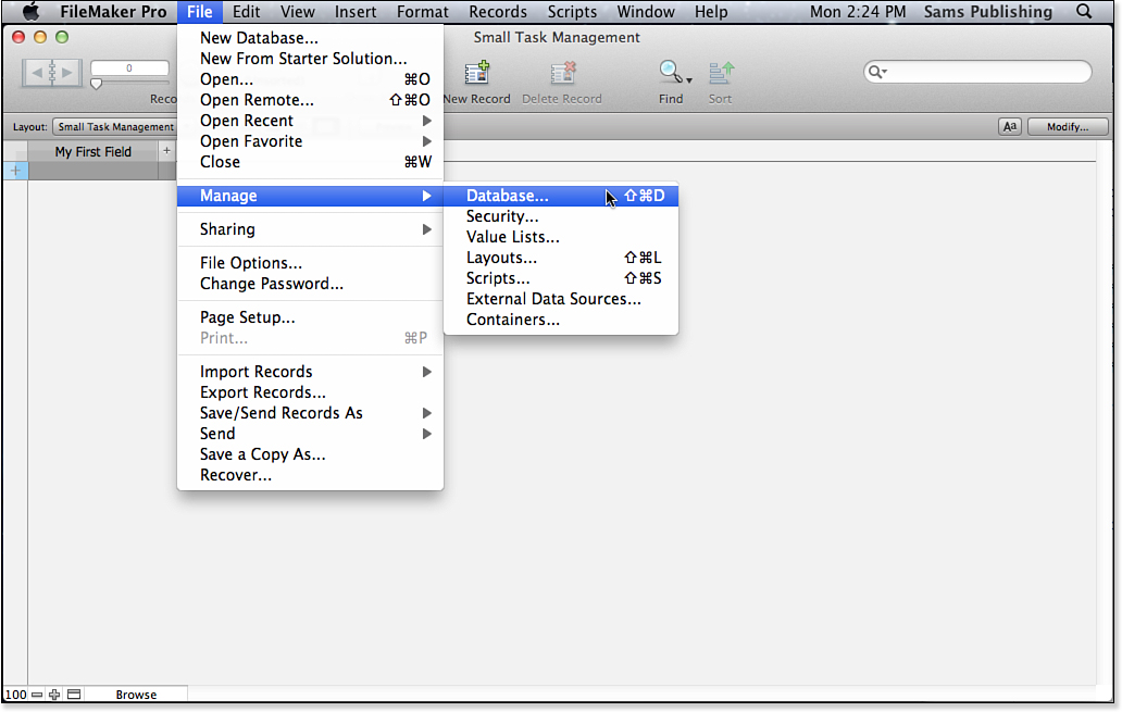
Figure 6.4. Use the Manage Database dialog.
One circumstance in which you probably want to use the Manage Database dialog is if you want to create several tables, as is the case here. For a multitable solution, the first step might be to rename the first table. Figure 6.5 shows the first table selected in the Tables tab of the Manage Database dialog; its name is about to be changed to Tasks.
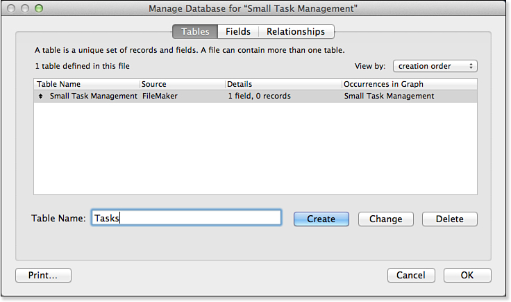
Figure 6.5. Rename the first table.
In Figure 6.6, you can see four fields created in the newly renamed Tasks table. They are the primary key, zzID; the due date for the task; the name of the task; and the foreign key that will identify the project in the project table when that is created. Later, there will also be the other four basic timestamp and identification fields described previously.
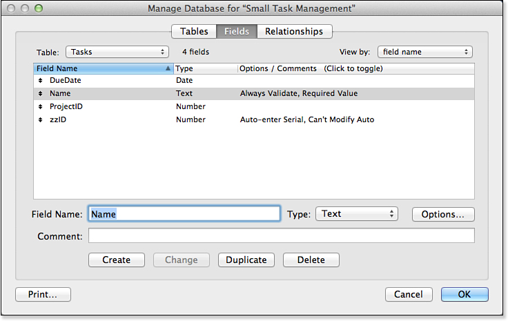
Figure 6.6. Field definitions for an initial table in a database of Tasks information.
![]() For a refresher on the details of creating fields within a single table in FileMaker, see Chapter 3, “Defining and Working with Fields and Tables.”
For a refresher on the details of creating fields within a single table in FileMaker, see Chapter 3, “Defining and Working with Fields and Tables.”
Adding a Table to a Multitable System
You’ve taken care of the Tasks table. To add a table for Projects, stay in the Manage Database dialog, but switch to the Tables tab. You see just one table, which in this example is called Tasks. To add a new table, type the name in the Table Name box and click Create. The new table is added to the list. This will be the Projects table, as shown in Figure 6.7.
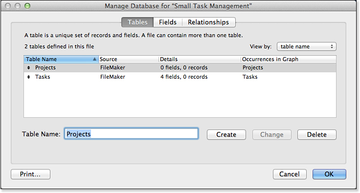
Figure 6.7. FileMaker’s Tables view, showing a database with multiple tables.
You’re now free to add fields to the new table. Figure 6.8 shows the basic starting fields for the Projects table.
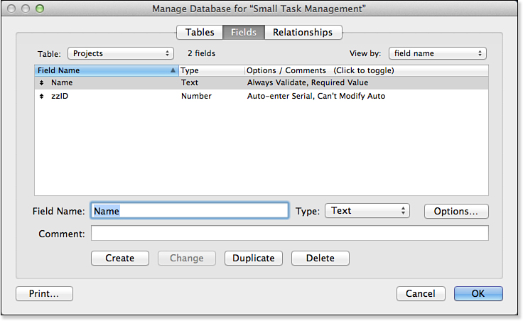
Figure 6.8. Field structure for a table of projects.
The Projects table automatically has a primary key (as do all tables that have an auto-entered zzID serial number). It does not need a foreign key as the tasks table does. The next section shows you why.
![]() For a refresher on primary and foreign keys, see “Understanding the Role of Keys in Database Design,” p. 161.
For a refresher on primary and foreign keys, see “Understanding the Role of Keys in Database Design,” p. 161.
Adding a Relationship
You now have two tables, as well as the primary and foreign keys that good database design demands. To create a relationship between these two tables, move to the Relationships tab of the Manage Database dialog. This window, known as the Relationships Graph, should have a couple of graphical elements already displayed. Each one represents one of the database tables that exist in this database. These elements are known as table occurrences. Each shows the name of the table it represents, along with that table’s fields.
Adding a relationship between these two table occurrences is simple: Draw a line from ProjectID in the Tasks table to zzID in the Projects table. You can also draw it in the other direction, from zzID in the Projects table to ProjectID in the Tasks table. Relationships have no direction in FileMaker Pro. You should see a line extend from one table to the other. When you release the mouse, FileMaker creates the relationship and displays it as a link between one or more match fields at the top of the table occurrence pair. Figure 6.9 shows how the Graph will look as a result.
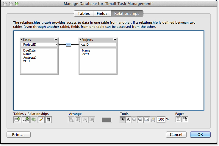
Figure 6.9. FileMaker’s Relationships Graph, with a relationship between two table occurrences.
You might have noticed the crow’s foot at the end of the relationship line where it touches the Projects table occurrence. This is none other than the indicator that you’re accustomed to seeing on the ERDs from the preceding chapter. It’s intended to indicate the “many” side of a one-to-many relationship.
At this point you’ve seen how to add a new table to FileMaker’s default one-table database configuration and how to define a one-to-many relationship between two FileMaker tables. The next sections clarify some important points about multitable systems.
Be warned, though! FileMaker provides this graphical adornment as a kind of a hint or guess about the relationship; it might not always be accurate (although, in this case, it is). You find out more in the next section, where the creation of key fields in FileMaker is discussed.
Working with Keys and Match Fields
You should remember from Chapter 5 that keys are fields within tables—fields that are essential elements in forming the relational structure of a multitable system. FileMaker takes a somewhat broader view of keys than many other relational databases, and for that reason these fields are referred to as match fields when you’re working in a FileMaker context. A match field in FileMaker is any field that participates in a relationship between two FileMaker tables. Primary keys and foreign keys fit this definition, of course, but so do a number of other types of fields explored in the next chapter.
![]() For more details on the broader uses of match fields in FileMaker Pro, see “Relationships as Queries,” p. 194, as well as other sections of Chapter 7, “Working with Relationships.”
For more details on the broader uses of match fields in FileMaker Pro, see “Relationships as Queries,” p. 194, as well as other sections of Chapter 7, “Working with Relationships.”
Key fields (which form the structural backbone of the system) need to play by some special rules—especially primary keys. Consider the current example, the Small Task Management database system, and consider the zzID field in the Projects table. This field has been identified as the primary key for the Projects table. To play the role of primary key, it must have a unique value. This was done automatically when you made it an auto-enter serial number in the Field Options dialog; this was further implemented by forcing it to have a unique value in the Validation tab and not allowing the user to modify it during data entry.
The Database So Far
At this point, you have created two tables and added fields to each of them. You have used the Manage Database dialog to create a relationship between them. You have also created two default layouts—or at least FileMaker Pro has done it automatically for you while you were working in the Manage Database dialog. The order of the fields in the layout reflects the sequence in which you created them.
You can create a new record by choosing New Record from the Records menu in Browse mode. The serial number (1) is automatically filled in, and you can type a project name, such as Chapter 6. Figure 6.10 shows the Tasks layout created for you with a single record entered.
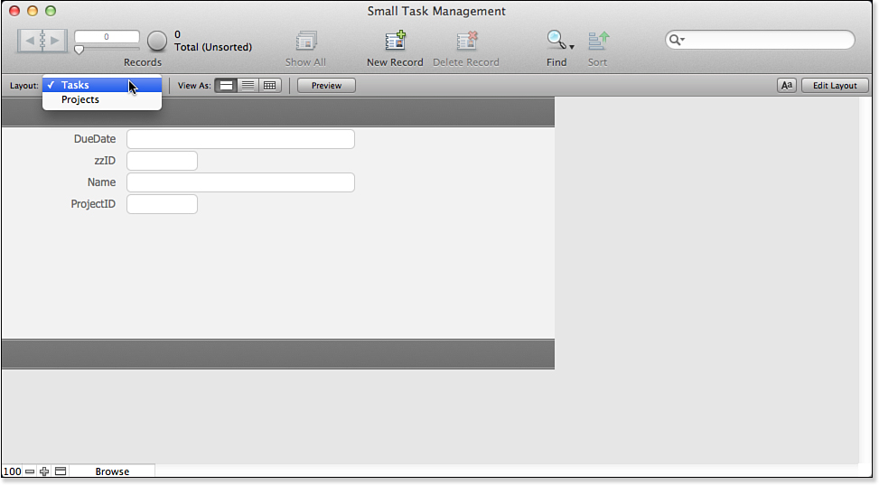
Figure 6.10. FileMaker Pro has created two layouts for you.
Working with Related Data
So far in this chapter you’ve learned how to create additional tables in a FileMaker system and how to build relationships between those tables based on well-constructed match fields. The following sections show you how to begin to use your relationships to work with and create data in multiple tables at once.
Using a Portal to View Related Child Data
The Small Task Management database system has two tables in it now, and there is a relationship between Projects and Tasks. In this example, a single record has now been created in the Projects table.
Now it is reasonable to create tasks for the project and to display them. You can do this with a FileMaker layout element called a portal. A portal lets you display multiple related records for a parent record in a layout.
![]() For additional discussion of the parent/child naming convention, see “Creating a One-to-Many Relationship in FileMaker,” p. 170.
For additional discussion of the parent/child naming convention, see “Creating a One-to-Many Relationship in FileMaker,” p. 170.
To create a portal on the Projects layout, choose the portal tool from the Status toolbar tools in Layout mode, as Figure 6.11 shows, and draw the portal in the approximate location you want it on the layout.
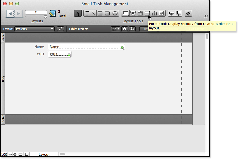
Figure 6.11. This is a layout in Layout mode, showing the FileMaker portal tool.
Although nothing prevents you from using a portal to display a one-to-one relationship, its design is optimized for the display of multiple records in a one-to-many relationship. The context or base table for the layout in which a portal is placed should be the “one” side of the relationship; the portal will be the “many” side. You can have multiple portals in a single layout, but they will all be the “many” sides of various relationships of which the base table is the “one.”
Click once on the tool, and then, on the layout, drag out a box wide enough to show the Task information and release the mouse. You get a dialog asking for details about the portal’s contents, behavior, and display. The dialog is shown in Figure 6.12.
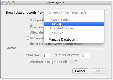
Figure 6.12. FileMaker’s Portal Setup dialog.
In general, when you set up a portal for the first time, you need to do the following:
• Choose a table occurrence from which to display data.
• Choose additional portal options.
• Choose data fields for display in the portal.
More details on each of these steps follow.
First, you need to specify where the portal gets its data. In the Portal Setup dialog, the Show Related Records From list enables you to choose which table to draw data from. The list is divided into sections: one for related tables and one for unrelated tables. (The Relationships Graph determines the question of whether a table is related or unrelated.) In the current example, for a portal on a layout in which the table context is the Projects table, there should be only one available choice in the menu: the Tasks table, which is the only other table related to Projects in the Relationships Graph. By choosing Tasks from this menu, you’re instructing FileMaker to show you all Tasks records related to the currently visible Projects record.
The Portal Setup dialog contains a number of other choices as well. For now, you can opt to display just four portal rows and put a vertical scroll bar on the portal so that you can scroll down if a project has more than four tasks. You can also apply coloring or striping to the portal if you choose.
FileMaker also displays a dialog at the end of the portal-creation process, asking which fields from the related table you want to show in the portal, as shown in Figure 6.13.
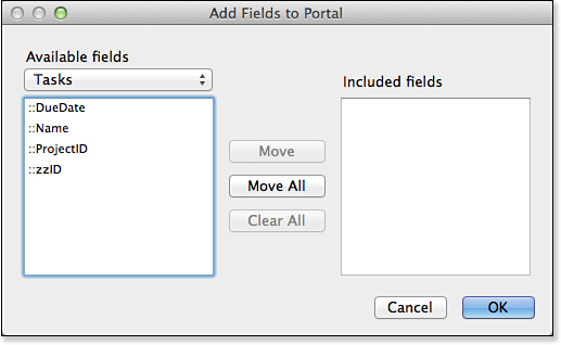
Figure 6.13. The Add Fields dialog shows the available fields in the related table.
You can double-click field names or select them and click Move to add fields to the portal. As with everything else in the portal design, you can come back later to make modifications if you want. Note also that the pop-up menu at the upper left of the Add Fields dialog lets you select other related table fields to display in the portal. After you have added fields to the portal list on the right, you can rearrange them by dragging the double-headed arrows up or down (see Figure 6.14).
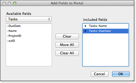
Figure 6.14. Reorder portal fields if necessary.
You can reopen the Portal Setup dialog by double-clicking the portal itself. Doing so lets you make other changes. You could, for example, click the Sort button to sort the data displayed in the portal, as shown in Figure 6.15. Here, the data is sorted in ascending order by date due (earliest first).
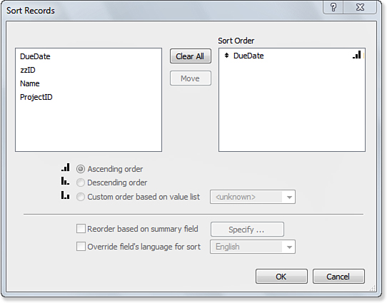
Figure 6.15. You can sort portal data.
In addition to sorting the portal, you usually want to add a scroll bar to it in the Portal Setup dialog. A check box lets you do this, as shown in Figure 6.16.
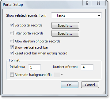
Figure 6.16. In the Portal Setup dialog, you can control where the data comes from, how it is sorted, and whether there is a scroll bar.
Now that you have set up your portal, you are ready to enter related records.
Fields are automatically added to a portal row the first time the Portal Setup dialog is shown, immediately after you have drawn the portal. Thereafter, you need to add them manually.
Using a Portal to Add Related Records
You can use portals for data entry as well as data viewing. You can even configure the portal and its underlying relationship so that a user can add Tasks to a Projects record by typing directly into the portal rows. To accomplish this task, you need to edit the relationship between Tasks and Projects. On the Relationships Graph, double-clicking the relationship line between the two tables brings up the Edit Relationship dialog, shown in Figure 6.17.
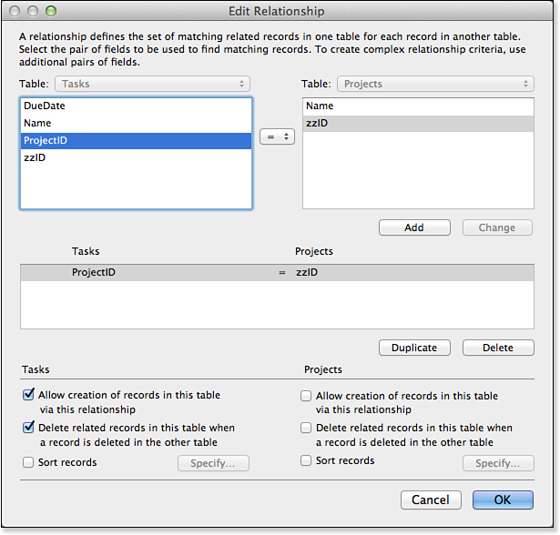
Figure 6.17. In the Edit Relationship dialog, you can edit individual relationships in the Relationships Graph.
For each table participating in a relationship, there’s an Allow Creation of Records in This Table via This Relationship check box under it. If you check this box on the Tasks side of the dialog, you are able to create task records via this relationship. You also can choose to delete related records automatically, which in this case is a good idea.
You cannot have a task without an associated project, so if the project is deleted, all its tasks should be.
Relationships in FileMaker have no direction, so you cannot tell which side a table will appear on in this dialog (the direction in which you drew the relationship actually determines it).
If you check this option and return to the Projects layout in the parent table, you’ll discover that you can now click an empty row of the portal and type in a task. If you do so, you automatically create a second, empty row for yet another task as soon as you have clicked out of the field into which you entered data. When the check box to allow creation of records is checked, you always have an empty row in the portal for data entry, as shown in Figure 6.18. With portals, it’s easy to view, create, and manipulate records on the “many” side of a one-to-many relationship.
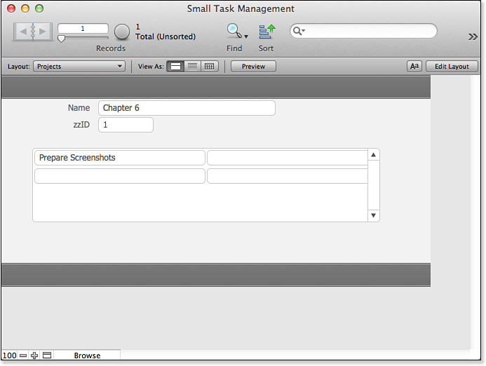
Figure 6.18. You can enter data in the portal for a related record.
You can add a feature to the portal to increase its usability: You can add a widget so that you can go to the related record. In Layout mode, select a widget from a Starter Solution or create one yourself and paste it into the portal row, as shown in Figure 6.19. Any graphic will do; at this point it is merely an image with no functionality.
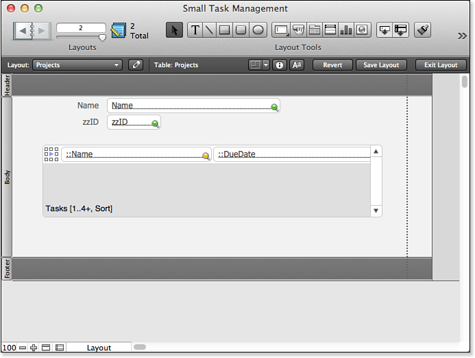
Figure 6.19. Add a widget to the portal row.
With the widget selected, choose Button Setup from the Format menu to open the dialog shown in Figure 6.20. (Alternatively, just double-click the widget.)
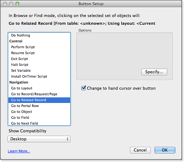
Figure 6.20. Use the Button Setup dialog to implement a button.
Choose Go to Related Record for the widget’s action, as shown in Figure 6.20. Click Specify to open the Go to Related Record Options dialog, shown in Figure 6.21.
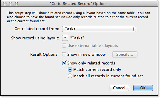
Figure 6.21. Set the table and layout to go to.
You will want to display records from the Tasks table. You can choose the layout to use (there is only one at this point, the default Tasks layout). Make certain that you use the check box at the bottom to show only related records.
Back in Browse mode, you will see your widget in the portal row; it is also in the next (empty) row at the bottom of the portal, as shown in Figure 6.22. If you click the widget in the first row (where you have entered data), you should go to the related Tasks record using the Tasks layout.
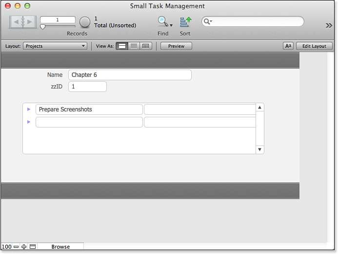
Figure 6.22. The widget lets you move to a related record in its own layout.
You have implemented a relationship in the database and implemented half the navigation needed to move around the relationship.
Working with Related Parent Data in a Child File
In the Tasks layout, you can make two improvements that will complete the process. First, add a merge field (Insert, Merge Field) in the header of the layout. From the Specify Field dialog shown in Figure 6.23, select Name from the Projects table.
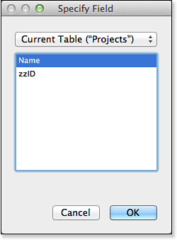
Figure 6.23. Add a merge field with the name of the related Projects record.
You can select the merge field and make it clickable by choosing Format, Button Setup. Repeat the process you used for the widget, but this time go to the related Projects record (you are already viewing the Tasks record), and use the Projects layout.
As shown in Figure 6.24, you now have the ability to move back and forth between projects and tasks.
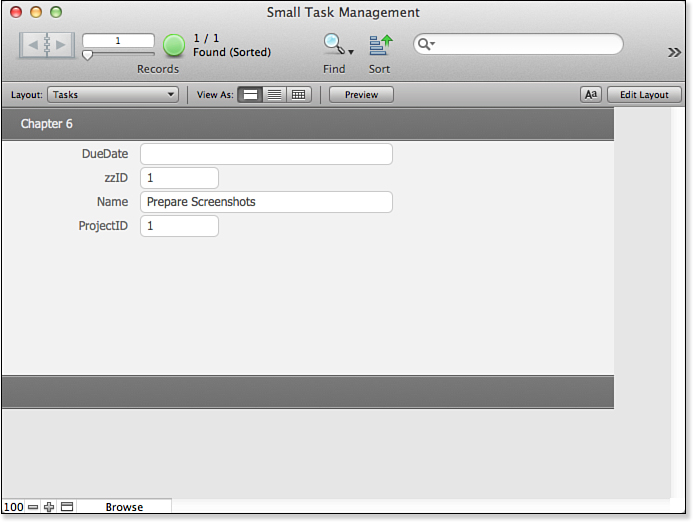
Figure 6.24. The Tasks layout now has a link to the related Project when you click the project name.
Creating a Many-to-Many Relationship
The preceding sections introduced you to most of FileMaker’s fundamental tools for working with multiple related tables. Now it’s time to extend those concepts and see how to use them to create a many-to-many relationship structure.
![]() As noted in “Many-to-Many Relationships” in Chapter 5, you can also implement a many-to-many join using a multivalued field and checkboxes.
As noted in “Many-to-Many Relationships” in Chapter 5, you can also implement a many-to-many join using a multivalued field and checkboxes.
Building the Structure
As described in the preceding chapter, a many-to-many relationship requires a join table. You have to add two tables to the Relationships Graph to implement a many-to-many relationship between tasks and contacts. The first is a Contacts table, which you can create exactly as you did the Projects and Tasks tables. For now, it is sufficient to give it a zzID and a Name field. Then create an Assignments table. This is the join table, and it needs three fields: its own zzID field, a TaskID field, and a ContactID field.
In the Manage Database dialog, create relationships between the Assignments table and the Contacts and Tasks tables. The process is the same as it was for relating Tasks to Projects. Your Relationships Graph should look like Figure 6.25 (subject to spacing variations).
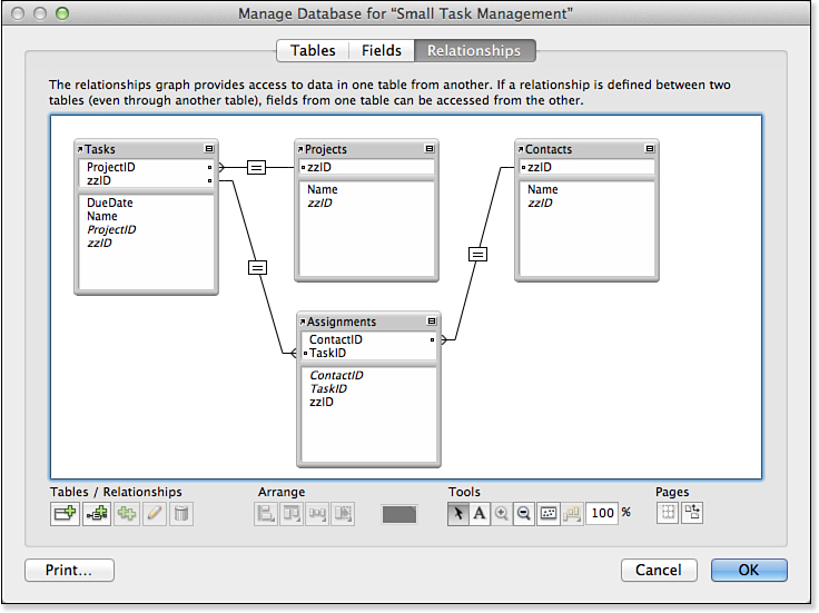
Figure 6.25. Add relationships for the join table.
Creating Value Lists
You can use value lists to let users choose the values for the fields in the Assignments table. This is a good idea because the table itself uses the meaningless ID numbers. You must have created the Contacts and Tasks tables to complete this step. To create a value list, choose Manage, Value Lists from the File menu or use the Manage icon in the status toolbar, as shown in Figure 6.26. When the Manage Value Lists dialog opens, click New to create a new value list.
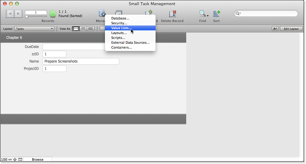
Figure 6.26. Manage the value lists.
The Manage icon shown in Figure 6.26 is not part of the standard status toolbar, but you can add it using View, Customize Status Toolbar. It is a very useful icon to add; many people add it to the Layout mode status toolbar.
The Edit Value List dialog shown in Figure 6.27 opens next. You want to use data from a field, so name the new value list Contacts, and then choose the first radio button; it opens the Specify Fields dialog.
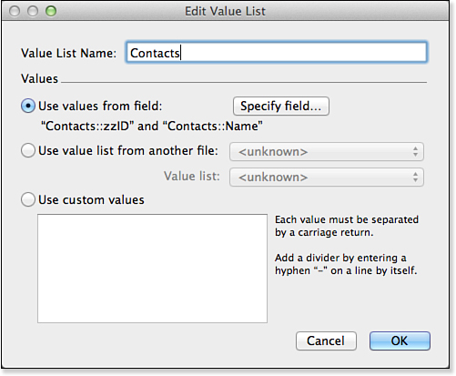
Figure 6.27. Use data from a field.
On the Specify Fields dialog shown in Figure 6.28, choose the zzID field from Contacts. Choose to show data from a second field—the Name field in Contacts—at the right of the dialog. Sort the data on the second field. Create a value list for Tasks in the same way.
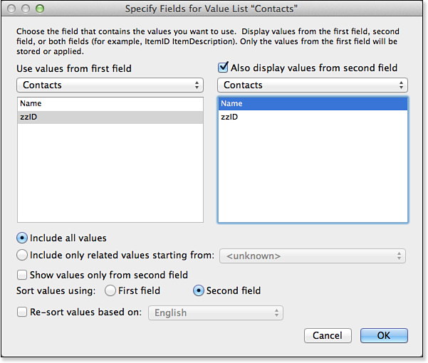
Figure 6.28. Choose the zzID and Name fields.
Designing the Interface
FileMaker Pro has created an Assignments layout for you automatically. You can modify that layout to make it more user friendly. The first thing to do is to make the ContactID and TaskID fields pop-up menus using the value lists you just created. Select the ContactID field in the default layout and set it to use the Contacts value list as a pop-up menu, as shown in Figure 6.29. Do the same for the TaskID field using the Tasks value list.
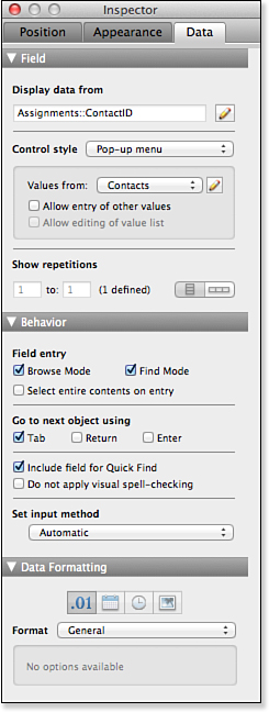
Figure 6.29. Use the value list for data entry.
If you add some new tasks to the database, your interface might look like Figure 6.30.
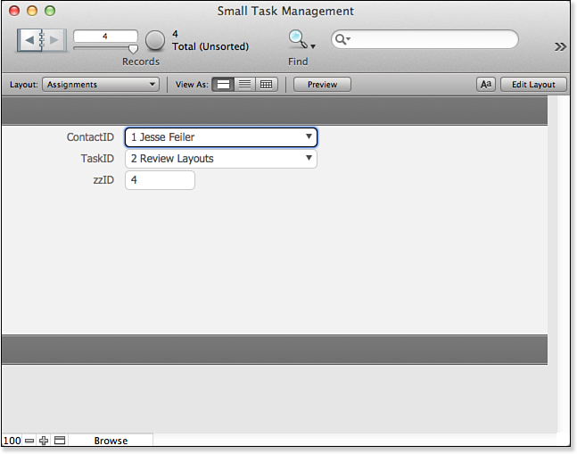
Figure 6.30. Your basic join table and its interface are complete.
You will find out more about relationships and layouts throughout this book. The principles are quite simple. It is important to remember that, compared to pre–FileMaker 7 databases, relationships can span many tables in the Relationships Graph. As long as a path can be found between two tables, they are related and you can use the relationship to construct portals and related fields.
As you build layouts, it is frequently a good idea to implement both sides of navigation—from a parent to child records (frequently using portals) and from a child record to its parent (with a widget—often in a portal row—that uses the Go to Related Record action). If you don’t do this, you might inadvertently construct traps that a user cannot easily get out of.
Another tip to remember is that frequently (but not always) it is the join table that should be the base table for a layout that will show a many-to-many relationship. Although the join table normally stays in the background, it has the information about both sides of the relationship.
Rapid Multitable Development
Working with the complex database schemas of a multitable file, or a solution composed of several such files, can sometimes be daunting. Using FileMaker Pro Advanced, you can import the definitions for multiple tables from one file to another. This schema import does not import any data, only the table and field definitions for selected tables. If you like to add a standard set of tables to most of your solutions (utility tables, logging tables, and resource tables), this procedure is now as simple as importing the table schemas from one file to another. It’s also possible to copy and paste table definitions, between or within files.
The same is also true of field definitions. They can be copied and pasted, either between files or within files, allowing you to quickly reuse blocks of standard fields. The enhancements extend to ScriptMaker as well, where you can copy and paste scripts and script steps with ease.
Troubleshooting
Repeating Portals
I’ve created a portal, but instead of seeing a set of different records, I see that every row of the portal shows exactly the same data.
This problem indicates a mismatch of table occurrences. Specifically, it suggests that although the portal is set to look at records from table occurrence A, the fields you’ve chosen to display in the portal are actually from table occurrence B. Because it’s possible to have several different table occurrences based on the same underlying table, it’s possible to see the same field list for several different table occurrences. Nevertheless, if the portal and the fields displayed in it draw from different table occurrences, you probably won’t get a meaningful display even if all the different table occurrences are based on the same underlying table.
Accidental Delete Restrictions
I set up a cascade-delete relationship between my Customer table and my Invoice table so that when I delete a customer, all related invoices are deleted as well. But when I try to delete a customer, I receive a message that I don’t have sufficient privileges. I checked my privileges, and I do have delete privileges in the Customer table.
Check to make sure you have delete privileges on the Invoice table as well. To perform a delete operation successfully in FileMaker, a user needs delete access to any and all records to be deleted. If you have delete privileges for Customer but not for Invoice, the entire deletion operation is forbidden.