
Day 27. Peripheral Devices and Connectors
CompTIA A+ 220-901 Exam Topics
![]() Objective 1.10 Compare and contrast types of display devices and their features.
Objective 1.10 Compare and contrast types of display devices and their features.
![]() Objective 1.11 Identify common PC connector types and associated cables.
Objective 1.11 Identify common PC connector types and associated cables.
![]() Objective 1.12 Install and configure common peripheral devices.
Objective 1.12 Install and configure common peripheral devices.
Key Topics
Today we will be focusing on the various types of display devices and their features. We will identify common PC connector types and their cables. We also will cover how to install and configure common peripheral devices such as mice, keyboards, and other devices.
Types of Display Devices
The display for any device comes in various varieties and sizes. They are output devices that present information in a visual format. Display devices have evolved to become smaller, slimmer, and more efficient. They are used in watches, phones, televisions, and even in medical or monitoring systems.
LCD Displays
Liquid crystal display (LCD) is a flat display technology that was first used in laptops and small devices like cell phones, calculators, and watches because of their thin, light characteristics and low power requirements. They are the most common type of display used today.
LCD displays use two sheets of polarizing material with a liquid crystal solution between them. The response time of an LCD display is measured in milliseconds (ms). Two categories of LCDs are available: passive matrix or active matrix display:
![]() Passive matrix LCDs—These use a simple grid of conductors with pixels at each intersection. They are cheap and easy to manufacture.
Passive matrix LCDs—These use a simple grid of conductors with pixels at each intersection. They are cheap and easy to manufacture.
![]() Active matrix or thin film transistor (TFT) LCDs—These refresh the screen more frequently and use individual transistors located at each pixel intersection. Active matrix provides a better picture because of its efficiency and the switching action of the transistors.
Active matrix or thin film transistor (TFT) LCDs—These refresh the screen more frequently and use individual transistors located at each pixel intersection. Active matrix provides a better picture because of its efficiency and the switching action of the transistors.
There are two different LCD technologies:
![]() Twisted nematic (TN)—A technology used in items such as watches and calculators. The idea behind it is the twisting of polarized light between the plates of glass. Twisted nematic was the only technology used in the 1980s and early 1990s. It is very fast but suffers from viewing angle distortion and an inability to display true black.
Twisted nematic (TN)—A technology used in items such as watches and calculators. The idea behind it is the twisting of polarized light between the plates of glass. Twisted nematic was the only technology used in the 1980s and early 1990s. It is very fast but suffers from viewing angle distortion and an inability to display true black.
![]() In-plane switching (IPS)—A display technology designed to solve limitations of twisted nematic field effects. It involves arranging and switching the orientation of liquid crystal molecules parallel to the screen. It offers a wider viewing angle and better color reproduction. It has great contrast and black levels but still suffers from ghosting and response times. This technology makes great displays for creative applications rather than consumer entertainment.
In-plane switching (IPS)—A display technology designed to solve limitations of twisted nematic field effects. It involves arranging and switching the orientation of liquid crystal molecules parallel to the screen. It offers a wider viewing angle and better color reproduction. It has great contrast and black levels but still suffers from ghosting and response times. This technology makes great displays for creative applications rather than consumer entertainment.
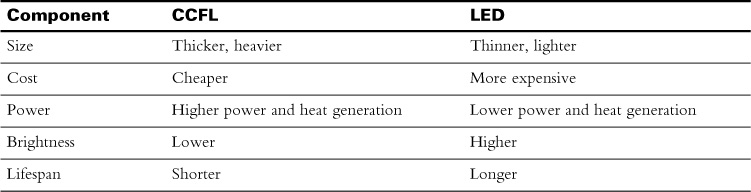
LED Versus CCFL Backlighting
LCDs do not produce light by themselves, so they need a source to illuminate images. This is accomplished with a backlight that is built in to them and that comes in two varieties:
![]() LED backlighting—It is not a new or better form of LCD display; it just uses light emitting diode (LED) technology for the backlight. All thin panel displays are still considered LCD display screens except for plasma. LED uses a matrix or strip of LEDs instead of a tube with an inverter. It is considered a green technology because it consumes less power and increases the longevity of a display device. It is a much brighter display and is the more popular of the two.
LED backlighting—It is not a new or better form of LCD display; it just uses light emitting diode (LED) technology for the backlight. All thin panel displays are still considered LCD display screens except for plasma. LED uses a matrix or strip of LEDs instead of a tube with an inverter. It is considered a green technology because it consumes less power and increases the longevity of a display device. It is a much brighter display and is the more popular of the two.
![]() Cold cathode fluorescent lamp (CCFL)—This older technology was the most widely used backlight in laptops and regular LCDs. It consists of a fluorescent tube connected to an inverter, which changes DC voltage back into AC. It is thicker and heavier than an LED with a shorter lifespan.
Cold cathode fluorescent lamp (CCFL)—This older technology was the most widely used backlight in laptops and regular LCDs. It consists of a fluorescent tube connected to an inverter, which changes DC voltage back into AC. It is thicker and heavier than an LED with a shorter lifespan.
Table 27-1 shows a summary of LED and CCFL backlighting comparisons. This type of comparison helps clarify both types to help you better memorize the components of each.
Plasma
Plasma and LCDs use entirely different methods to create colors. The idea behind using plasma in flat-panel displays is to illuminate tiny, colored fluorescent lights lined with phosphor. They are filled with inert ionized gas to form an image similar to the way a neon sign works.
Because they use direct lighting instead of a backlighting system, they have an extremely bright picture with a wide viewing angle. Unfortunately, plasma screens are susceptible to burn-in, have a shorter life span, have difficulty displaying black, and are not as high resolution as LCD screens.
Projectors
A projector is an optical device that can take images, video, or data generated on a computer and reproduce it on a flat surface. Generally they are used in business or education or by home movie enthusiasts to display information to multiple people at one time. They can be relatively small, portable, and easy to use.
A projector’s throw ratio is defined as the projector’s ability to control the size of what is being displayed. It is the distance measured from lens to screen divided by the width of the image projected or the width of the screen. For example, a throw ratio of 2:1 might mean that the projector is 18 feet away from the screen and the display width is 9 feet. Viewing distance is defined as the distance between the viewer and the screen.
Organic Light-emitting Diode
Organic light-emitting diode (OLED) is an LED that uses organic semiconductor molecules made of carbon-based materials to create thin light-emitting panels. They work by putting red, green, and blue materials tightly together so that when they are powered, a white light is created. This light then passes through a color filter to create red, green, and blue pixels. The emitter materials can be either fluorescent or phosphorescent with the former lasting longer.
The two types of OLED technology are traditional, which use small organic molecules deposited on glass, and light-emitting polymers (LEPs), which are printed onto plastic rather than on glass. These are thinner and more flexible.
The many advantages of the OLED technology include thinner displays, more efficiency, longer life-span, ease of scalability, brilliant colors, and the fact that they do not require a backlight or filters. In addition, they produce truer colors and a much bigger viewing angle. The disadvantages are that they do not last as long as LCDs and are sensitive to water.
Video Settings
You can work with the settings for the video card by going into Device Manager, right-clicking the device, and then selecting Properties. Other times you will find a specific program installed in the Control Panel that will give you access to the driver settings. For example, NVIDIA and ATI will both have some type of additional utility program installed in the Control Panel.
Display Settings for Windows—A Control Panel Display applet provides options to adjust resolution, calibrate color, as well as work with other display settings. Settings include previously configured text sizes or custom dots per inch (DPI) settings. It also contains a link to Change Display Settings, such as smaller 100%, medium – 125%, and large – 150% (which can be used to adjust the appearance of the display).
With two or more displays, adjustments can be made to which one is primary, which type of orientation they use, whether the displays are extended or duplicated, or whether the desktop is shown only on one or another. If a display is not shown, clicking the Detect button will attempt to find it.
Another way to get to the Display applet is to right-click a free spot on the desktop and select Personalize. From here, you can change desktop icons, account pictures, desktop backgrounds, and Window color. Plus, you can enable the screen saver as well as access links to the mouse pointer and sound settings.
Display Settings for OS X—In Apple’s OS X, changes to the display happen under the Apple menu > System Preferences > Displays. It also can be accessed by holding the Option key while pressing one of the brightness adjustment keys. Resolution and brightness can be adjusted. There also is an option for dealing with multiple displays, detecting multiple displays, and changing their arrangements. Extending the desktop happens automatically. Selecting Gather Windows enables the user to drag windows to an external screen and helps to track open windows.
Display Settings in Linux—Most Linux distributions have both a GUI and a command-line interface. With the command line, using xdpyinfo will provide information that includes the current display resolution. xrandr will show the current resolution as well as possible display settings. For the GUI, you usually can find a display configuration tool located under System Settings.
Monitor Settings—Monitors also have drivers that enable them to work with the operating system (OS). Most rely on drivers that are already included with the OS. It is rare to need a special driver for use with a monitor unless one of the following is true:
![]() The monitor has special features such as a built-in sound system or USB ports.
The monitor has special features such as a built-in sound system or USB ports.
![]() The monitor is incompatible with the OS.
The monitor is incompatible with the OS.
![]() The monitor has settings that need adjusting through software.
The monitor has settings that need adjusting through software.
Refresh/Frame Rates
A refresh rate is the number of times a display is repainted on the screen, or how often the display shows a new image. Its unit of measurement is a Hertz. A display of 120 Hz can draw 120 images per second, matching the number of times the liquid crystal material is illuminated. LCDs can run with refresh rates of 120 Hz and 240 Hz. The higher the refresh rate, the less motion blur will be a problem.
The measurement of frames per second (fps) a screen can display is a little different. 60 fps is the norm in the United States because our electricity runs at 60 Hz. If video is set to run at 90 fps, it will try to send those frames to the monitor at that speed. If the monitor can’t display more than 60 Hz, the video card will still send the additional frames, which causes images in motion to blur. Unless the device has a high refresh rate, it cannot display high frame rates accurately.
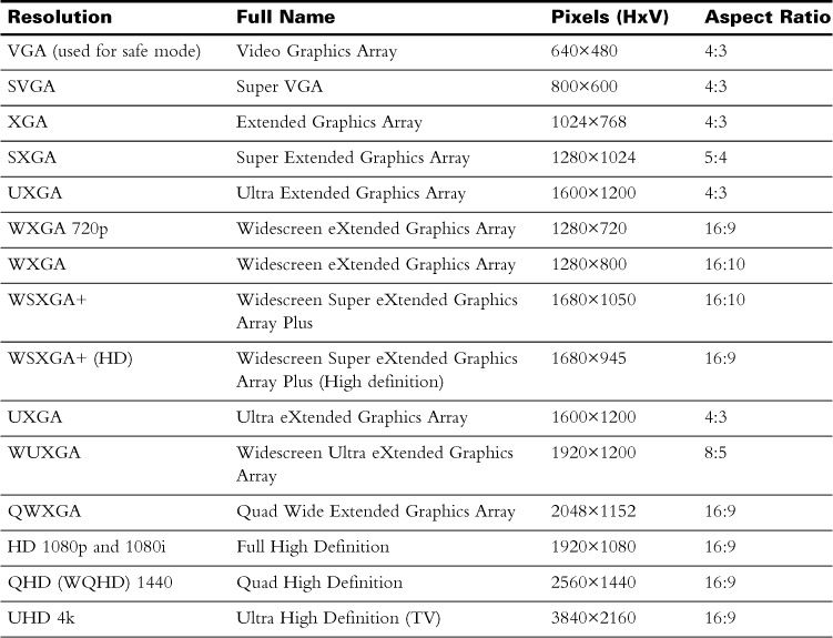
Resolution/Aspect Ratio
With display devices, resolution is measured by the number of pixels going both horizontally and vertically (HxV). When resolution increases, the picture becomes sharper. Picture clarity also is affected by the size of the device. The smaller the monitor, the more density of pixels per inch.
The best resolution for an LCD monitor is the one that is recommended by the manufacturer, called the native resolution. Changing the native resolution can cause small text to be centered on the screen, a black edge, or a stretched look.
The aspect ratio of an image is defined as the relationship between the width and height of a picture expressed in two numbers separated by a colon (for example, 4:3 or 16:9). A 16:9 ratio means a picture that has 16 pixels running horizontally will have 9 pixels running vertically. In the early days, everything was created with a 4:3 ratio, but now we have wider aspect ratios where the most common picture is shown as 16:9.
Table 27-2 lists some of the more common resolutions and their aspect ratios as well as the pixel count.
Brightness/Lumens
The brightness of a graphic display is a description of light output, which is measured in nits. A nit is a measurement of light emission that is used to describe the luminance of a screen or how dense the light is on a screen. An LCD monitor’s backlight determines how bright the monitor can appear. Average monitors range in the 300-nit range with high-end monitors going up to 1000 nits.
When talking about a projector bulb, we measure by lumens. A lumen is a measurement of light intensity. It covers the area that the light is hitting. Lumens can help determine how far away from a projection surface you need to be or how bright a projection will be.
Analog Versus Digital Displays
Analog signals use waves as a means of sending and receiving data. Digital signals are in either an on state or an off state, which are represented by 1s and 0s. LCD monitors should use a digital connection; older CRT monitors use analog. Some monitors can accept either digital or analog ports. There are also transceivers that can change a signal from analog to digital, or vice versa. Figure 27-1 shows a typical analog-to-digital conversion between the monitor and NIC card.
Digital signals have a higher quality than analog and are the most popular video signal used today. Analog signals can be carried in separate channels called multichannel component video. This is where the red, blue, and green colors have their own interfaces. High-end graphic workstations use the multichannel component video.
Privacy/Antiglare Filters
A privacy filter reduces the viewing angle and makes the screen black to anyone trying to view from an angle. Antiglare filters reduce any glare and reflections caused by light. Both can provide privacy or increase user comfort.
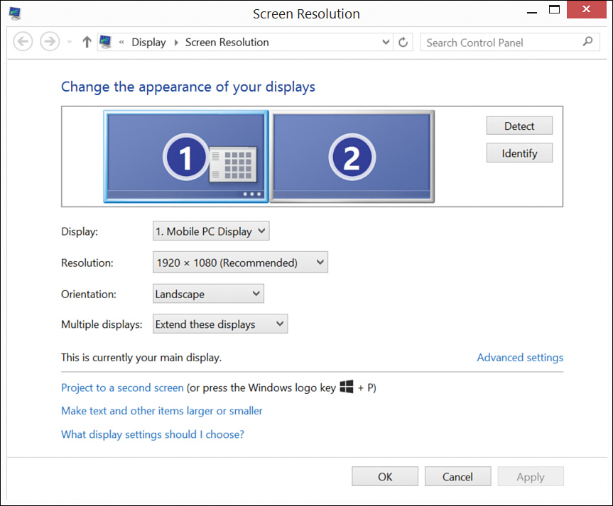
Using Multiple Displays
To create a multiple monitor setup, use a video card that supports multiple ports, or use two or more video cards. With a laptop, an external video port enables the use of both the port and the integrated display at one time.
Usually Windows will automatically detect both monitors. To implement dual monitors in Windows, use the Display applet. Click the Change setting where you can configure which monitor is primary and whether the second monitor is a duplicate of the first screen or an extension of it. See Figure 27-2 for an example of the Windows 8 Display applet.
Display Connector Types
A video port connects to a monitor using a cable. These cables transmit both digital and analog signals. The signals are sent from the computer to the graphics card where they are transmitted through a cable to a display or monitor. Sometimes both video and audio is sent through the same cable. There are several types of video ports and connectors to study for the exam.
Multimedia connectors—These are used to connect audio and video hardware to a computer. Here are some things to know about the various types of multimedia connectors:
![]() Video Graphics Array (VGA)—This connector is often blue; has 15 pins; and is used by older, analog monitors.
Video Graphics Array (VGA)—This connector is often blue; has 15 pins; and is used by older, analog monitors.
![]() High Definition Multimedia Interface (HDMI)—Carries both video and audio to high-definition monitors and televisions. There are five types of connectors:
High Definition Multimedia Interface (HDMI)—Carries both video and audio to high-definition monitors and televisions. There are five types of connectors:
![]() Type A is a standard HDMI connector used for audio/video connections.
Type A is a standard HDMI connector used for audio/video connections.
![]() Type B is never used.
Type B is never used.
![]() Type C is designed for use with digital equipment.
Type C is designed for use with digital equipment.
![]() Type D is designed for compact portable equipment (cell phones).
Type D is designed for compact portable equipment (cell phones).
![]() Type E is designed for automotive applications.
Type E is designed for automotive applications.
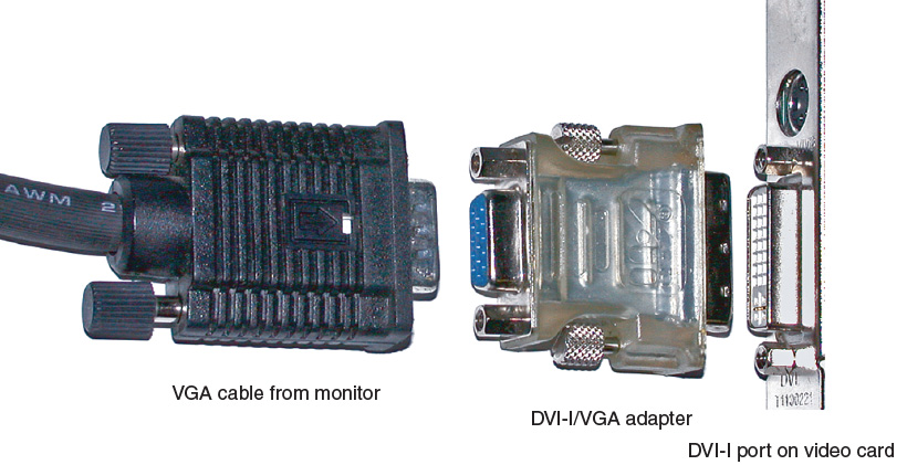
![]() Digital Visual Interface (DVI)—Carries video and/or audio to LCD displays. The following are five types of DVI connectors:
Digital Visual Interface (DVI)—Carries video and/or audio to LCD displays. The following are five types of DVI connectors:
![]() DVI-D—The most commonly used digital-only connection, it is usually found on newer LCD monitors. Comes in both single and dual link.
DVI-D—The most commonly used digital-only connection, it is usually found on newer LCD monitors. Comes in both single and dual link.
![]() DVI-A—Supports analog only.
DVI-A—Supports analog only.
![]() DVI-I—Supports both digital and analog. Comes in both single and dual link.
DVI-I—Supports both digital and analog. Comes in both single and dual link.
![]() DVI-DL—The DVI-DL does exist, but it is not as widely used as the first three. It doubles the power of transmission and provides increases in speed and signal quality.
DVI-DL—The DVI-DL does exist, but it is not as widely used as the first three. It doubles the power of transmission and provides increases in speed and signal quality.
![]() M1-DA—Created by VESA in the late ’90s, it is a dual-link DVI that includes USB support.
M1-DA—Created by VESA in the late ’90s, it is a dual-link DVI that includes USB support.
![]() DisplayPort—Designed to connect high-end graphics and displays as well as home theater equipment. It also comes in a mini size and is primarily used on Apple computers.
DisplayPort—Designed to connect high-end graphics and displays as well as home theater equipment. It also comes in a mini size and is primarily used on Apple computers.
![]() Audio—Carries audio to speakers and can collect input from microphones. The analog connectors on sound cards are color-coded to indicate which connector to use for which speaker or device. Often, these cards have digital interfaces, known as the Sony/Phillips Digital Interconnect Format (S/PDIF). This interface uses light pulses over fiber-optic cable.
Audio—Carries audio to speakers and can collect input from microphones. The analog connectors on sound cards are color-coded to indicate which connector to use for which speaker or device. Often, these cards have digital interfaces, known as the Sony/Phillips Digital Interconnect Format (S/PDIF). This interface uses light pulses over fiber-optic cable.
Multiple types of DVI connectors exist on video cards that can easily become confusing. Figure 27-3 shows the various types of DVI plugs and pins to memorize.
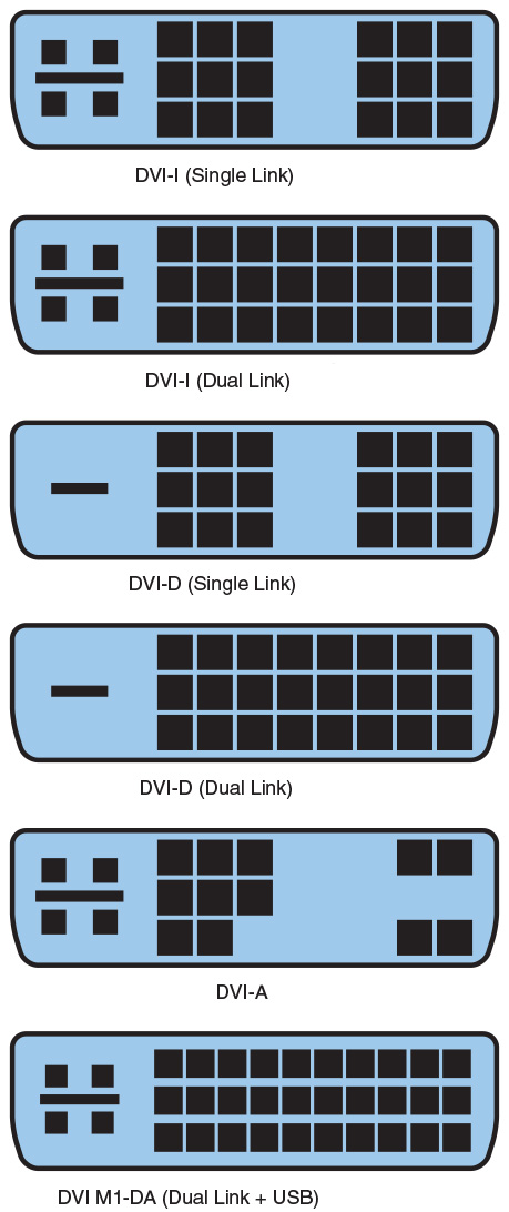
Figure 28-2 from Day 28, “PC Component Installation, Part 2,” details some available video ports.
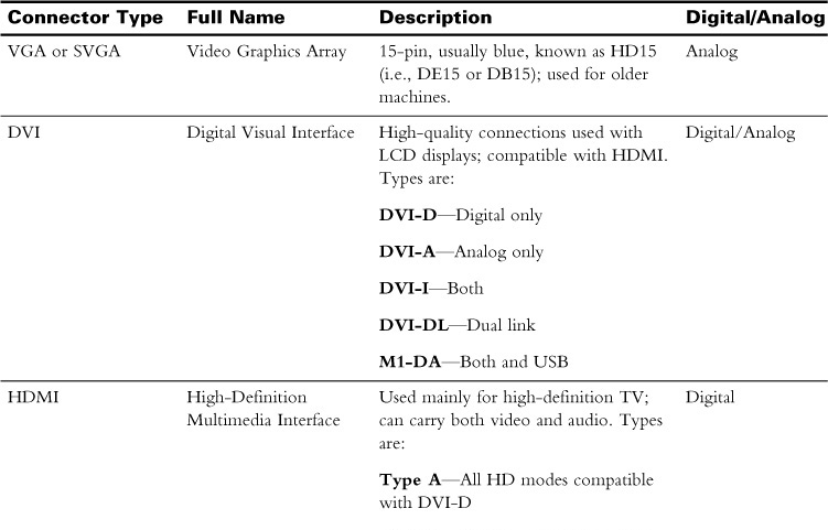
Video devices use a variety of interfaces for both analog and digital formats. A physical connector and signal protocol are used to control signal communication. Table 27-3 describes the connector type and whether it is digital or analog.
Device Cables and Connectors
Input/output ports enable users to connect hardware in a variety of ways through a variety of port types. The designation of input is understood to be anything that enables the human to input signals in to the CPU and memory, such as the mouse or keyboard. Output is understood to be anything that the computer itself sends out to the human such as a printout or video. The following ports are typical for most computers and allow it to communicate with other hardware devices on the inside or outside of the computer.
SATA and eSATA
Serial ATA (SATA) cables have a 15-pin power connector and a 7-pin data connector and provide a point-to-point connection between the motherboard and hard drive or CD/DVD/BD unit. Power supplies provide +3.3V, +5V, and 12V to a SATA drive. Older SATA drives can run only at their designed speeds—even if they are connected to a newer controller. Encoding can affect actual transfer rates.
An eSATA port is designed to connect a hard drive’s data port external to the computer. It uses shielded cables up to 2 meters and has stricter electrical standards. Because an eSATA port is an extension of the SATA bus, it can provide up to 16 Gb/s depending on the SATA revision installed on the motherboard.
Universal Serial Bus
Universal serial bus (USB) ports are the most common type of port found on today’s computers. They were created to replace parallel and serial ports and are now used by almost every type of device. The port can not only control the device, but many times can provide power to it as well.
The three standards for USB ports refer to the versions: USB 1.1, USB 2.0, and USB 3.0. USB 3.0 markings usually have a different color and have a different symbol from either version 1.0 or 2.0 connections.
A USB host controller is an integrated circuit built in to the chipset of the motherboard. It can control up to 127 USB devices. Inside the host controller is a USB root hub that is a shared communication channel. A motherboard that supports more than one USB version will provide a separate host controller for each. Devices cannot send data until they are polled by the host. A USB adapter or up to five hubs can be added to the machine if more ports are needed.
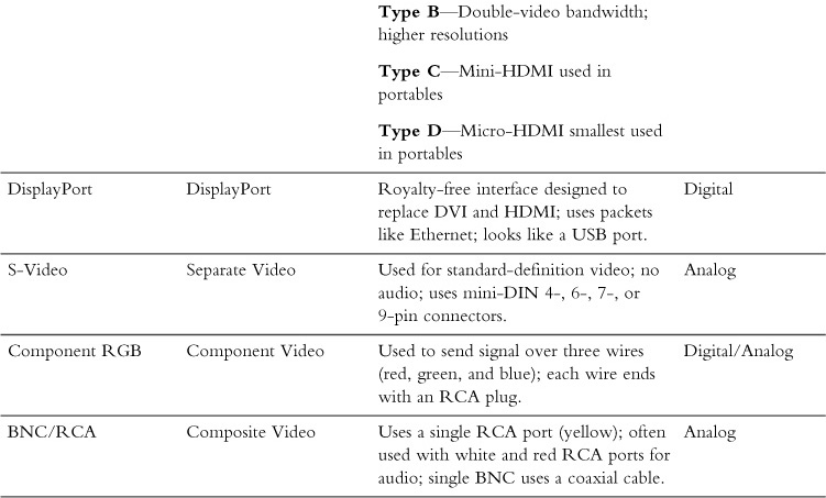
The most common plugs used for USB connections are Type A and Type B, which are commonly used for printers. Mini and micro connectors are used for handhelds, smartphones, mice, and other small devices.
In 2015, USB 3.1 introduced a new type C connector. It has symmetrical connectors on both ends, meaning each end is the same and can be plugged into either device. It provides better charging capabilities and data transfer rates. Figure 27-4 shows all USB connection types.
FireWire IEEE 1394
IEEE 1394 is also referred to as FireWire. It is a standard that was used by Apple and has since been replaced with Thunderbolt. Used for devices such as music or video, it can handle up to 63 devices with no more than 16 devices in a chain. Table 28-2 in Day 28 describes the differences between version 1394a and 1394b in greater detail.
PS/2
A PS/2 port is used for an older-style mouse (cyan color) or a keyboard (magenta color). Devices connect through a six-pin Mini-DIN connector. These connections are much less common now with USB being faster and more efficient. Expect to see some ports that can support both a mouse or a keyboard and are half magenta and half cyan in color.
Audio Ports
Audio ports are many times integrated with the motherboard. A sound card can be installed separately in an expansion slot if a more powerful system is required. Audio ports are color-coded based on the PC System Design Guide, version PC 99, as follows:
![]() Light blue—Line input
Light blue—Line input
![]() Pink—Microphone
Pink—Microphone
![]() Lime green—Output for speakers
Lime green—Output for speakers
![]() Black—Output for surround sound speakers (rear)
Black—Output for surround sound speakers (rear)
![]() Silver/brown—Output for additional speakers (middle)
Silver/brown—Output for additional speakers (middle)
![]() Orange—Output for center speaker and subwoofer
Orange—Output for center speaker and subwoofer
Media Converters
Sometimes the type of port on the computer does not match the type of connector or cable that is available. In these instances a converter can provide a way to connect the two different style ports. Manufacturers can make almost any type of port converter needed for connectivity, such as the following examples:
![]() DVI to HDMI
DVI to HDMI
![]() USB A to USB B
USB A to USB B
![]() USB to Ethernet
USB to Ethernet
![]() Thunderbolt to DVI
Thunderbolt to DVI
![]() PS/2 to USB
PS/2 to USB
![]() HDMI to VGA
HDMI to VGA
![]() DisplayPort to DVI
DisplayPort to DVI
![]() DisplayPort to HDMI
DisplayPort to HDMI
![]() Activity 27-1: Identify Ports on a Computer
Activity 27-1: Identify Ports on a Computer
Refer to the Digital Study Guide to complete this activity.
Installing and Configuring Common Peripheral Devices
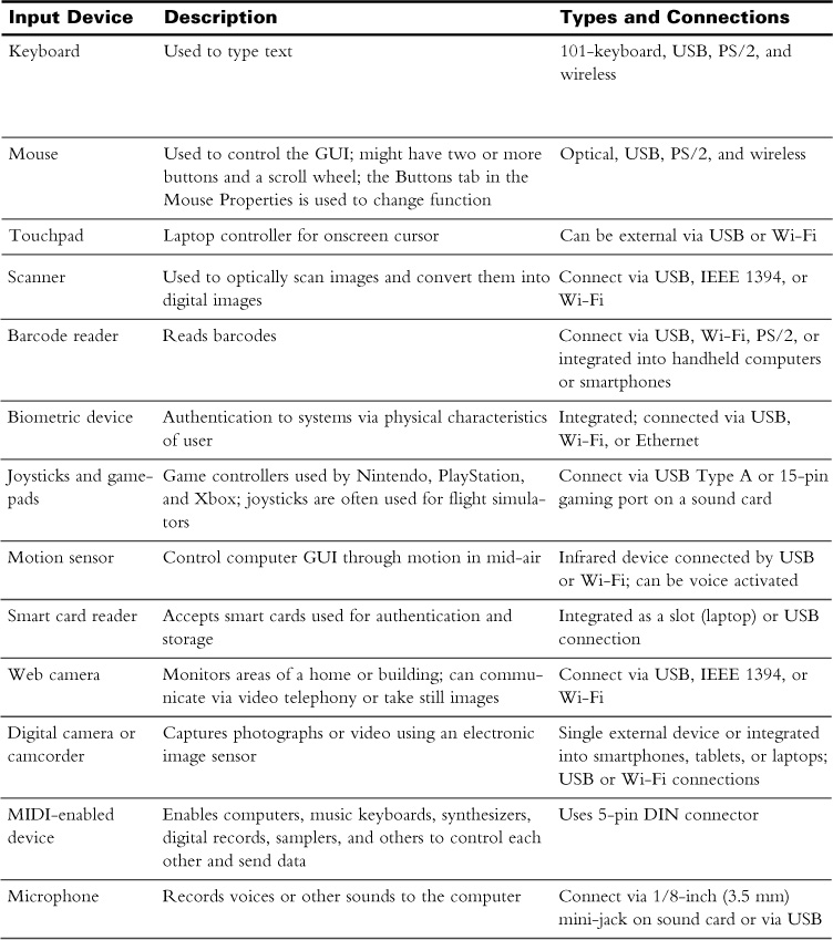
All input/output devices must work with a driver matched to the operating system running on the computer to which it is attached. Table 27-4 details typical input devices and connection types.
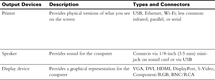
Output devices are designed to provide the results of data that has been processed inside the computer to a user or another computer. Table 27-5 lists the most common output devices.
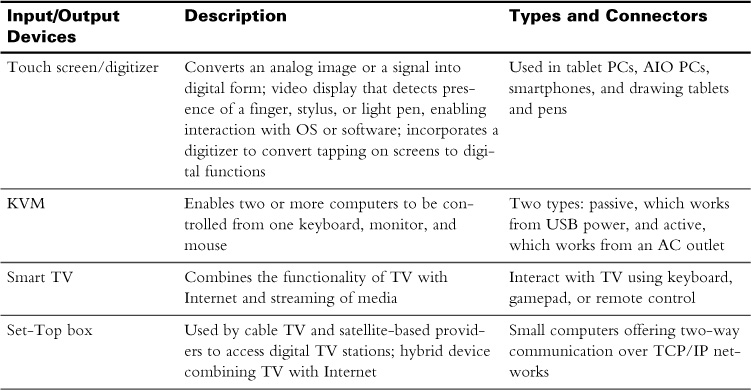
Some devices can provide both input and output depending on how they are used, as detailed in Table 27-6. Other devices not mentioned here also can be both input/output devices, such as modems, network cards, headsets that contain both speakers and microphones, audio cards, and so on.
![]() Activity 27-2: Identify If a Device Is Input or Output
Activity 27-2: Identify If a Device Is Input or Output
Refer to the Digital Study Guide to complete this activity.
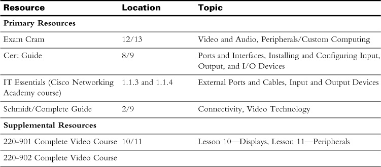
Study Resources
For today’s exam topics, refer to the following resources for more study.
![]() Check Your Understanding
Check Your Understanding
Refer to the Digital Study Guide to take a quiz covering the content of this day.