Chapter 4. Unified CM Call Routing and Digit Manipulation
This chapter covers the following topics:
• Pattern Matching: This section describes how Unified CM analyzes both numeric and alphanumeric sequences in order to match a configured pattern and then routes the call to the desired destination. This section also covers the mechanisms by which the digits can be manipulated as they traverse the system.
• Transformations and Masks: This section discusses operations such as discarding digits, transformation mask application, and prefixing digits to alter calling and called numbers.
• Pattern Configuration and Device Selection: This section describes the steps taken to locate an end device or devices through the use of route patterns, route lists, route groups, hunt pilots, hunt lists, and line groups.
• Partitions and Calling Search Spaces: This section discusses the methods by which patterns in Unified CM can be placed into logical groups for the purposes of class of service restrictions, regional variations in dial plan, time of day routing, and more.
• Translation Patterns: This section describes a dial plan element used to manipulate calling and called party numbers and perform powerful modifications during the call routing and digit analysis process in Unified CM.
• Transformation Patterns: This section discusses transformation patterns, which, like translation patterns, can be leveraged to perform calling and called party modifications but are typically applied once a call has been routed to a device.
• Putting It All Together: Tail-End Hop Off (TEHO): This section shows how all the dial plan constructs described in previous sections of this chapter can be put together to implement tail-end hop off (TEHO).
• Alphanumeric URI Routing: This section describes the unique characteristics of alphanumeric URIs and how they are handled and routed in Unified CM.
• Intercluster Dial Plan Replication: This section explains the mechanisms available to share dial plan–related information between multiple Unified CM clusters in order to facilitate both numeric and alphanumeric dialing across an enterprise.
• Troubleshooting Call Routing and Digit Manipulation: This section describes various tools and diagnostic logs that can help troubleshoot issues related to call routing.
This chapter covers the following CLACCM 300-815 exam topics:
• 4.1 Configure these globalized call routing elements in Cisco Unified Communications Manager
• 4.1.a Translation patterns
• 4.1.b Route patterns
• 4.1.c SIP route patterns
• 4.1.d Transformation patterns
• 4.1.e Standard local route group
• 4.1.f TEHO
• 4.2 Troubleshoot these globalized call routing elements in Cisco Unified Communications Manager
• 4.2.a Translation patterns
• 4.2.b Route patterns
• 4.2.c SIP route patterns
• 4.2.d Transformation patterns
• 4.2.e Standard local route group
• 4.2.f TEHO
• 5.2 Configure ILS, URI synchronization, and GDPR
• 5.3 Configure hunt groups
• 5.4 Configure call queuing
• 5.5 Configure time of day routing
The primary purpose of Cisco Unified Communications Manager (Unified CM) is to collect digits or alphanumeric sequences from a user or source device and determine the appropriate destination for that call. This chapter goes into detail on the various dial plan elements available in Unified CM that, when combined, provide instructions on how to route calls throughout the system. Unified CM has, arguably, the most flexible and powerful call routing engine of any comparable platform; however, this flexibility comes at the cost of some level of complexity. This chapter provides details on how these dial plan elements interact with each other to form the call routing engine of Unified CM. The majority of the configuration options discussed in this chapter are found in the Call Routing menu in the Unified CM Administration user interface.
“Do I Know This Already?” Quiz
The “Do I Know This Already?” quiz allows you to assess whether you should read the entire chapter. If you miss no more than one of these self-assessment questions, you might want to move ahead to the “Exam Preparation Tasks” section of the chapter. Table 4-1 lists the major headings in this chapter and the “Do I Know This Already?” quiz questions related to the material in each of those sections to help you assess your knowledge of these specific areas. The answers to the “Do I Know This Already?” quiz appear in Appendix A, “Answers to the ‘Do I Know This Already?’ Quiz Questions.”
Table 4-1 “Do I Know This Already?” Foundation Topics Section-to-Question Mapping

1. Which of the following matches the numbers in the range 1000 through 1999 on a route pattern in Unified CM?
a. 1…
b. 1XXX
c. 1***
d. 1{3d}
e. 1!
2. Which of the following are valid transformation masks? (Choose three.)
a. +1919555XXXX
b. 1XXX
c. 1***
d. [2-9]XXXX
e. +44XXXXXXX
3. Which of the following allow you to apply an external phone number mask to a number? (Choose three.)
a. Route pattern
b. Route list
c. Route group
d. Line group
e. Calling party transformation pattern
f. Called party transformation pattern
4. Which of the following are distribution algorithms you can configure on a route group? (Choose two.)
a. Longest Idle
b. Top Down
c. Bottom Up
d. Circular
e. Randomized
5. Which of the following must be present in a route pattern to be able to use digit discard instructions? (Choose three.)
a. X
b. !
c. @
d. .
e. #
6. Where can call queuing be configured?
a. Route pattern
b. Hunt pilot
c. Route list
d. Hunt list
e. Line group
7. Which statement is true of partitions and calling search spaces?
a. Partitions contain unordered lists of calling search spaces.
b. Calling search spaces contain unordered lists of partitions.
c. Partitions contain ordered lists of calling search spaces.
d. Calling search spaces contain ordered lists of partitions.
e. Route patterns and directory numbers can be placed in a calling search space.
8. Which of the following best describes the calling abilities of a device with a calling search space set to < None >?
a. This device will not be able to place any outbound calls because the CSS is empty.
b. This device will be able to place outbound calls to any device or pattern in the < None > partition.
c. This device will not be able to receive any inbound calls.
d. This device will only be able to receive inbound calls from others configured with the < None > calling search space.
9. Which of the following parameters can be configured on a translation pattern but not on a route pattern?
a. Calling Search Space
b. Route Partition
c. Do Not Wait For Interdigit Timeout On Subsequent Hops
d. Use Originator’s Calling Search Space
e. Use Calling Party's External Phone Number Mask
10. A user dials 1000, which matches the translation pattern 1XXX. This translation pattern is configured to transform the called party number with a mask of 2XXX. Using the calling search space on the translation pattern, a match is found for a route pattern 2XXX, which is configured to route the call to a route list. On the route pattern, you configure the called party transformation mask 3XXX. On the route list that matches, in the route list details for a route group, you configure the called party transformation mask X5XX. This route group matches a SIP trunk with a called party transformation CSS configured. In that CSS, you have the following called party transformation patterns configured:
• 1XXX transforms the called party to 1111
• 15XX transforms the called party to 1555
• 2XXX transforms the called party to 2222
• 25XX transforms the called party to 2555
• 30XX transforms the called party to 3333
• 35XX transforms the called party to 3555
What will be the called party number when the call is presented to the destination of the SIP trunk?
a. 1111
b. 1555
c. 2222
d. 2555
e. 3333
f. 3555
11. A called party transformation of 456.XXXX is configured with the following settings:
Digit Discard Instructions: PreDot
Called Party Transformation Mask: 11XXXX
Prefix Digits: 123
If a user dials 4568888, and it matches this pattern, what is the resulting called party number?
a. 1238888
b. 1118888
c. 123118888
d. 1234118888
e. 8888
12. What is the first step in routing a call when building a scalable dial plan that includes tail-end hop off?
a. Localize the calling and called party numbers to look for hop off matches
b. Use Global Dial Plan Replication to advertise TEHO patterns
c. Globalize the calling and called numbers to +E.164 format
d. Match a route pattern with a route list containing the remote gateway or trunk
e. Ensure that all patterns are configured for urgent priority
13. Which statements are true of URI routing? (Choose two.)
a. Local directory URIs are placed into partitions.
b. ILS learned directory URIs are placed into partitions.
c. SIP route patterns are placed into partitions.
d. The cluster fully qualified DN is used when routing non-numeric URIs.
e. The organization top-level domain is used when routing non-numeric URIs.
14. What are the different modes a cluster can be in when it is part of an ILS network? (Choose two.)
a. Stand Alone Cluster
b. Hub
c. Spoke
d. Client
e. Server
15. Which troubleshooting tools allow you to view a ladder diagram of SIP signaling? (Choose three.)
a. Dialed Number Analyzer
b. SIP Call Processor
c. TranslatorX
d. Real-Time Monitoring Tool
e. Collaboration Solutions Analyzer
16. What happens to a call if the following line appears in an SDL trace file?
potentialMatches=NoPotentialMatchesExist
a. The call fails immediately.
b. The call is routed immediately.
c. The call is routed after waiting for interdigit timeout.
d. The call fails after waiting for interdigit timeout.
e. Not enough information is provided.
Foundation Topics
Pattern Matching
To configure a dial plan in Unified CM, an administrator must specify the phone numbers or alphanumeric URIs that a user can dial. These sequences are generally referred to as patterns. A variety of dial plan configuration elements—such as route patterns, translation patterns, and directory numbers—provide fields for an administrator to configure patterns. Regardless of the dial plan element, patterns all behave the same way throughout the system.
Patterns allow an administrator to configure either numeric strings (for example, 1000 for extension 1000), numeric patterns containing wildcards (for example, 1XXX, which matches the numbers 1000 through 1999), or alphanumeric patterns (for example, a URI such as [email protected]). Before delving into the various dial plan elements that can accept one of these patterns, it helps to understand the various wildcards available and how Unified CM examines a dialed number or URI to find a matching configured pattern. Although there are similarities between numeric and alphanumeric patterns, it helps to examine them separately.
Numeric Matching
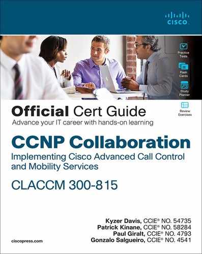
Let’s first discuss how Unified CM deals with numeric patterns. As mentioned earlier, a numeric pattern can be a sequence of digits or can contain a variety of wildcard characters that can match more than one digit. Table 4-2 describes the various numeric wildcard characters available in Unified CM.
![]()
Table 4-2 Wildcard Characters for Numeric Patterns
All of the elements listed in Table 4-2 can be combined in any order in a pattern with the exception of the ? and + wildcards, which must be preceded by at least one other digit or wildcard. For example, to describe a 10-digit number in the North American Numbering Plan (NANP), an administrator could configure the following pattern:
[2-9]XX[2-9]XXXXXX
A phone number in the NANP comprises a three-digit area code, three-digit office code, and four-digit subscriber number. The area code and office codes cannot start with either a 0 or a 1. As a result, the wildcard sequence [2-9] is used to exclude the digits 0 and 1, and the X wildcard indicates the digits, which can be 0 through 9.
You might be tempted to use [^01] instead of [2-9] as, at first glance, they may appear to mean the same thing. However, [^01] would be equivalent to [2-9#*] because * and # are also valid digits, and [2-9] is far more readable.
To allow a user to dial the digit 9 followed by the 10-digit number to indicate the desire to place a PSTN call, the pattern would look like this:
9[2-9]XX[2-9]XXXXXX
The leading 9 in this case is sometimes called an access code, dial-out pattern, or steering digit. This digit is not part of the number the user wants to dial but rather indicates what kind of number follows the steering digit—in this case, a PSTN number. These steering digits are typically removed before routing the call to the final destination, so it is useful to delimit the portion of the pattern that represents the part that should be removed. The period or dot character can be used for this purpose as follows:
9.[2-9]XX[2-9]XXXXXX
Recall that the dot does not match any digits or affect the way the pattern is matched. It simply acts as a delimiter that can later be used with digit discard instructions, as discussed later in this chapter. Although 9 is the most common steering digit, the steering digit can be different. There may also be more than one type of steering digit in a dial plan used to direct calls to different parts of an organization, depending on the particular design and deployment. Alternatively, a design might not use steering digits at all but instead might require users to just dial all numbers as they would from a home phone or mobile phone.
To represent a North American number in +E.164 notation, this is the pattern to use:
+1[2-9]XX[2-9]XXXXXX
Notice that this pattern starts with a + wildcard, which matches exactly one instance of the character +. A backslash escape character () is necessary because the + wildcard already means something different.
Closest-Match Routing
In many scenarios, there may be a variety of different configured patterns that match a sequence of digits provided by an end user. For example, consider a Unified CM cluster with the following patterns configured:
1000
100X
10X5
1[^1]XX
1XXX
1!
If a user dials the number 1000, which destination does Unified CM select? The function in Unified CM that is responsible for determining the correct destination is called digit analysis. This component is part of the Cisco CallManager service that runs on all Unified CM servers that perform call processing functions. Digit analysis finds the “best” match for a dialed number by using closest-match routing. For each matching pattern, digit analysis considers the number of possible matches for a given pattern. For example, the pattern 100X can match 10 possible numbers—from 1000 through 1009. The pattern 1XXX can match up to 1000 numbers—from 1000 through 1999.
![]()
It is not obvious how many numbers the 1! pattern matches. You might be tempted to think it matches an infinite number of digits because the pattern matches a variable number of digits—for example, 10, 1000, 1000000, and 1000000000 are all valid matches for the 1! pattern—but for the purposes of closest-match routing, digit analysis only evaluates the number of potential matches given the number of digits dialed. In other words, if a user dials 1000, digit analysis treats the 1! as 1XXX, which means it also matches 1000 possible numbers.
So back to our example: If a user dials 1000, it’s easy to see that the pattern 1000 is the best match because it matches exactly 1 number. But what if a user dials 1005? That sequence matches 100X, 10X5, 1XXX, and 1!, with 100X and 10X5 each possibly matching 10 numbers. Which one does digit analysis choose? In this scenario, it is non-deterministic, meaning that you don’t know which one will be used. Later, when we discuss partitions and calling search spaces, you will learn of a way to give priority to one or the other, but in general, it is not a good practice to have such ambiguity in your dial plan.
What if a user dials the digits 1100? Which is the best match in this case? You might be tempted to pick 1[^1]XX because your first instinct might be to consider this to be equivalent to 1[02-9]XX, which would match 900 different patterns as opposed to the 1000 patterns matched by 1XXX and 1! In this case, however you would be wrong in assuming this. The caret (^) notation includes the *, #, A, B, C, and D digits as well, so 1[^1]XX actually potentially matches 1500 different patterns and is therefore not as good a match as 1XXX. It turns out that 1! in this case also matches 1000 patterns, so again, the result is not deterministic between 1XXX and 1!. Be very careful with overlapping patterns to always ensure that you understand which pattern is a better match.
Digit-by-Digit Versus Enbloc Calling
Generally speaking, Unified CM performs digit-by-digit analysis of numeric patterns. This means that, as the name implies, it searches for a match as each digit is entered by a user (for example, SIP IP phone via KPML). In contrast, with enbloc calling, the originating device sends all the digits at once (for example, SIP server via SIP INVITE). Enbloc calling can also occur when the user of an IP phone dials a number from a directory (click to call) or invokes a function such as redial, where the entire number to be dialed is already known by the phone.
Let’s use the same patterns as before for an example of digit-by-digit matching:
1000
100X
10X5
1XXX
1!
If a user picks up a phone and dials the digit 2, Unified CM recognizes that there are no patterns that could possibly match because none of the patterns permit the first digit to be a 2. In the terminology of digit analysis, there are no potential matches because no pattern could potentially match if the user were to continue dialing more digits.
On the other hand, if the user dials the digit 1, all the patterns are considered potential matches; however, none of them actually are matches. When the user dials a second digit—for example, the digit 5—the situation changes significantly. First of all, 1000, 100X, and 10X5 are no longer potential matches. 1XXX is considered a potential match because, if the user were to dial two more digits, it would match. 1! in this scenario is a bit unusual in that it is both a match and a potential match. It is a match because the digits 15 match the pattern 1! (1 followed by one or more numeric digits) but could also possibly match additional digits as well because this pattern allows for one or more digits after the 1.
![]()
When Unified CM is in a situation where it has found a match, but potential matches still exist, it does not route the call immediately and, instead, continues to wait for more digits until the interdigit timeout (also known as the T.302 timer) expires. There are some exceptions to this rule. If the pattern that matched is configured with urgent priority, the call is routed immediately, even if potential matches exist. In addition, if the call arrives to Unified CM via a signaling channel that does not support digit-by-digit transmission of digits—for example, on a SIP trunk—then Unified CM looks for a match immediately and does not consider the possibility that more digits could arrive. When we discuss translation patterns later in this chapter, you will also see that an administrator can indicate to the system that, in certain scenarios, digit analysis should not await further digits by using a configuration parameter on the translation pattern.
Alphanumeric URI Dialing
With the introduction of alphanumeric uniform resource identifier (URI) dialing in Unified CM, the product gained the ability to dial not just phone numbers but also URIs that look similar to email addresses in the format user@domain (for example, [email protected]).
URIs have two distinct components, separated by the @ sign. The component to the left of the @ is sometimes referred to as the left-hand-side (LHS), or the user portion, and, as you may have guessed, the component to the right is referred to as the right-hand-side (RHS), or the host portion.
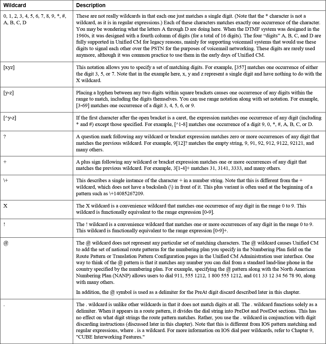
Unified CM generally matches URIs based only on an exact match. URIs are always sent in a single request, so digit-by-digit processing or potential matches do not apply to alphanumeric URIs. If there is no exact match for a URI, Unified CM tries to route the call based on the host/RHS portion of the URI only. When routing based on just the host portion, there are only a few wildcards, as described in Table 4-3.
![]()
Table 4-3 Wildcard Characters for Alphanumeric URI Patterns
When dealing with URIs, there are several rules that determine how Unified CM routes these calls. These rules are discussed later in this chapter, in the section “Intercluster Dial Plan Replication,” as the concepts discussed there are essential to the process of routing URIs.
Transformations and Masks
Once Unified CM has matched a pattern, some dial plan elements allow administrators to define transformations on those numbers to modify either the calling and/or called party number before moving on to the next dial plan element or device. Transformations and masks are used in a variety of configuration elements in Unified CM, and understanding how they work is essential to having a good understanding of how dial plans work in Unified CM.
Note
Don’t be confused by the difference between transformations and transformation patterns. Transformation patterns are discussed later in this chapter. Transformations can be configured on a variety of dial plan elements, including, but not limited to, transformation patterns, route patterns, translation patterns, and route lists.
Generally, three types of transformations can be performed using Unified CM:
![]()
• Digit discard instructions
• Transform mask
• Prefix digits
Digit Discard Instructions
Digit discard instructions allow you to modify a number by discarding specific digits determined by the selected option. Many of the choices defined in the digit discard instructions selection are tied directly to the numbering plan selected and apply only when a pattern contains the @ wildcard. These numbering plan–specific digit discard instructions are seldom used, primarily because the @ wildcard is not commonly recommended when configuring the North American Numbering Plan and most other numbering plans that can be added to Unified CM do not include any special digit discard instructions.
The most commonly used digit discard instructions are PreDot, Trailing-#, and PreDot Trailing-# (which combines the first two options). The names of these digit discard instructions are self-explanatory. The PreDot digit discard instruction removes any digits that appear before the dot in a pattern. If a pattern does not contain a dot, the digit discard instruction has no effect. The Trailing-# digit discard instruction removes a # character if found at the end of a pattern. (When we discuss a more complex dial plan later in this chapter, you will see how the trailing # is used to indicate end of dialing in variable-length calling scenarios.) The final option, PreDot Trailing-#, discards both the digits before the dot as well as the trailing #, if present.
Transform Masks
Transform masks provide a powerful way to manipulate arbitrary digits in a number string. They allow an administrator to add, remove, or change numbers in a digit string before sending that number to the end device or the next dial plan element. Masks can be thought of as addition problems, where the number to be modified and the mask to be applied are right-aligned and then the digits in the number and mask are compared to determine the result. A mask can contain either a digit (0-9, *, #, +) or an X. A specific digit or character replaces the digit at that position with the one in the mask. The X character keeps the existing digit at that position. The mask can also be shorter or longer than the number of digits in the number to be modified. Let’s look at some examples that illustrate how this works.
In this first example, we start with the number 2000 and apply the mask 408555XXXX:
Original number |
|
Mask |
|
Final result |
|
You can see that the mask transforms the extension into a 10-digit number. This mask might be used to transform the calling party number for presentation to the PSTN.
As another example, say a user dials 9 to indicate a PSTN call and then dials the 10-digit number 4085551234 (so the full sequence of dialed numbers is 94085551234). To convert this number to +E.164 format, an administrator would have to remove the 9 and then prefix the characters +1, with the + indicating +E.164 format and the 1 indicating the country code for the NANP. In order to accomplish this task, the administrator can apply the mask +1XXXXXXXXXX as follows:
Original number |
|
Mask |
|
Final result |
|
Notice how in a mask, to prefix a + character you do not include the backslash character the way you do when indicating the + character in a pattern.
As a final example, consider the case of the number 2000 with the mask +1XXXXXXXXXX. What happens in this scenario?
Original number |
|
Mask |
|
Final result |
|
In this case, the final result has digits that are unknown because an X is being applied to a nonexistent digit. In this scenario, the entire number is discarded because it is invalid. Care should be taken to ensure that scenarios like this do not occur.
Prefix Digits
The final form of transformation by using prefix digits. The Prefix Digits field allows administrators to, as the name implies, prefix digits to a number. The prefix is applied regardless of the number of digits. For example, if the Prefix Digits field is set to 9, the numbers 10, 100, and 1000 are transformed to 910, 9100, and 91000, respectively.
Combining Transformations
![]()
The three transformations mentioned—digit discard instructions, transform masks, and prefix digits—can all be used at the same time on some dial plan elements. Not all of them are available on all dial plan elements. For example, digit discard instructions are generally only applicable to called party numbers. Sometimes only a transform mask is available. Whenever more than one transformation is available, the transformations all apply, and the order in which they are applied is important. When we dive into some of the specific dial plan elements, you will see that the Unified CM Administration UI displays the transformations in the order which they are applied, which makes the order easy to determine. However, generally speaking, the order is always digit discard instructions followed by transform mask followed by prefix digits.
For example, a route pattern (as discussed in the next section) permits an administrator to transform the called party number with digit discard instructions, a transform mask, and prefix digits—applied in this order. An administrator could have a pattern such as 9.[2-9]XX[2-9]XXXXXX configured to discard PreDot, apply the transform mask 1XXXXXXXXXX, and then prefix +:
Dialed number |
|
Route pattern |
|
Discard |
|
New number |
|
Transform mask |
|
New number |
|
Prefix |
|
Final number |
|
Note
This example is just for illustrative purposes because it would be much easier to just apply a mask of +1XXXXXXXXXX to achieve the same result. However, you will find that in some scenarios, using one or more of the transformations is easier.
Now that you know how Unified CM finds the best pattern using digit analysis and the tools available to manipulate numbers, let’s move on to more specifics on where these patterns are configured and how patterns are mapped to an end device or feature that can process the call.
Pattern Configuration and Device Selection
Unified CM provides a variety of configuration constructs for assigning numbers or ranges of numbers to devices and features. This chapter largely focuses on how dialing a number or URI results in a call being routed to a device, whether it be a locally registered device such as a phone or a destination that is reachable by traversing a gateway or trunk to reach an external system or other network. Patterns associated with specific features are discussed in greater detail in Chapter 6, “Unified CM Call Control Features.” As you will see, patterns are configured similarly, regardless of whether they are being configured on a device or on a feature.
The patterns that Unified CM allows you to configure ultimately associate a called device or feature with a particular number or alphanumeric sequence. For example, if an administrator assigns the pattern 2000 as the directory number on a phone line, the desired outcome is for the phone line to ring when the number 2000 is called. As you will see, the call routing logic can be significantly more complicated than this, but you should understand the basics of where patterns can be configured. The following sections provide details on the various pattern configurations.
Directory Numbers
A directory number is the most basic pattern configuration. It assigns a pattern to a line on a device, whether it be a physical phone, a soft client such as Cisco Jabber or Webex Teams, or a virtual device such as a Remote Destination Profile or CTI Route Point.
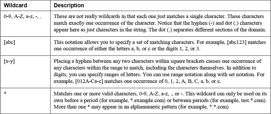
You typically configure directory numbers by navigating to the configuration page for a phone (accessed through Unified CM Administration > Device > Phone) and then selecting one of the directory numbers available for that device. You can also configure directory numbers independently of the phones they appear on by navigating to Unified CM Administration > Call Routing > Directory Number. Figure 4-1 shows the pattern +19195551234 being configured as a directory number on an IP phone line. (Note that after you click Save when adding a line, the Active checkbox disappears, so you see this option only while adding a line or if when looking at a directory number that is not assigned to a phone.)
Figure 4-1 Directory Number Configuration on a Line
In nearly all real-world scenarios, a directory number does not contain any wildcards. This is because a line on a phone is typically assigned a single number rather than a range of numbers that would cause that line to ring; however, there is nothing stopping an administrator from configuring wildcards on a directory number.
A directory number directly associates a pattern to one or more devices. Multiple devices can share a directory number. This is referred to as a shared line appearance. A shared line appearance allows for multiple devices to ring at the same time when a directory number is dialed, and a user can answer the call on any of the devices that are ringing. A call on a shared line appearance can be placed on hold and resumed on other devices sharing that line. A shared line appearance is a prerequisite for features such as barge, a feature that allows a user to join (barge) into an active call on a shared line.
Note that while multiple devices can share a single directory number, there are some configuration parameters that apply to the appearance of a shared line on a specific device. For example, the text label used to display the line on a phone can be different between two devices sharing the same line. More critically for the purposes of call routing and digit manipulation, each line appearance of the same directory number can have different external phone number masks.
![]()
The external phone number mask is an important parameter to understand, as it can be used to manipulate the calling party number when sending calls out to the PSTN or other external systems. As the name implies, the external phone number mask is a transform mask. By itself, the external phone number mask has no effect on calling or called party numbers. Other configuration parameters that we will discuss shortly can selectively decide whether to use the external phone number mask during the course of routing a call to its ultimate destination. The external phone number mask is also leveraged as part of the automated alternate routing (AAR), feature which attempts to reroute calls that fail between locations if the amount of bandwidth is exceeded. In the case of a CAC failure, the external phone number mask is used along with the AAR group configuration to determine the PSTN number to use to reroute the call.
Note
An administrator can configure alternate numbers associated with a directory number. Alternate numbers are discussed later in this chapter, in the section “Global Dial Plan Replication.”
Another unique characteristic of directory numbers is that this is the only way that Unified CM allows an administrator to configure a name associated with a number. There are two distinct names that can be configured on a directory number: the alerting name and the display name. The alerting name is presented to a device that places a call to the directory number. For example, if directory number 2000 has an alerting name configured as Line Name 2000, if Phone A places a call to 2000, the display on Phone A shows that the destination is Line Name 2000.
Remember that directory numbers can appear on various phones as shared line appearances. Each shared line appearance of a directory number allows an administrator to configure the display name. Continuing the previous example, if Phone B and Phone C both have directory number 2000 configured, the display name could be configured differently for the line appearances on those phones. For example, directory number 2000 appearing on Phone B could be configured with the directory name Phone B 2000, and the directory number 2000 appearing on Phone C could be configured with the directory name Phone C 2000. If Phone A dials 2000, Phone A still shows the destination name of the call as Line Name 2000, as in the previous example, but after the call is answered, the display changes, depending on whether Phone B or Phone C answers the call. If Phone B answers the call, Phone A now shows Phone B 2000 as the connected name, whereas if Phone C answers the call, Phone A shows Phone C 2000 as the connected name. Table 4-4 illustrates this example by indicating what appears on the calling party device for the alerting and connected party names.
Table 4-4 Shared Line Alerting and Connected Name Example
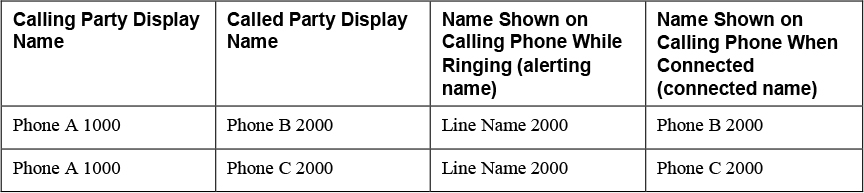
Whenever a call originates from a phone line, the display name is always used as the calling party name. This does not change the way that the called/connected party name changes when the call is answered. Using the same example as in Table 4-4, the remote called party phone would show an inbound call from Phone A 1000 on the display during both the alerting (ringing) phase and when the call has been answered.
The final point to mention regarding the display and alerting name configuration is that the Unified CM Administration user interface has a configuration page with two fields, one of which allows you to configure the ASCII version of the name. The ASCII version is used for any devices that do not support UTF-8-encoded text. This applies to a small number of legacy phones and, more importantly, applies to any SIP trunks that do not have the Transmit UTF-8 for Calling Party Name setting configured.
Route Patterns, Route Lists, and Route Groups
Route patterns, route lists, and route groups work together to allow an administrator to route calls from a Unified CM cluster to an external destination. This includes routing calls to PSTN gateways such as CUBE and Expressway for B2B video calls, and it could even extend to routing a SIP trunk to another Unified CM cluster, such as a Session Management Edition (SME) cluster. The destination device can be a gateway device (Unified CM Administration > Device > Gateway) or a trunk device (Unified CM Administration > Device > Trunk). Gateways include MGCP, H.323, and SCCP gateways, while trunks include SIP and H.323 intercluster trunks (both gatekeeper and non-gatekeeper-controlled).
At a high level, a route pattern allows an administrator to configure a pattern that, when matched, routes a call either directly to a gateway or trunk device or to a route list. A route list is an ordered list of route groups that are used to find the appropriate destination, and a route group is a collection of one or more gateways or trunks. Together, these three constructs allow an administrator to route calls to external systems while also providing load balancing and redundancy. Although the routing logic matches in the order route pattern, then route list, then route group, then gateway/trunk, you must configure these in the opposite order because you must have a gateway or trunk configured before you can add it to a route group, you must have a route group configured before you can configure the route list, and you must have the route list configured before you can add a route pattern. (Chapter 5, “Unified CM SIP Trunk Configuration,” goes into detail on how to configure SIP trunks.)
Figure 4-2 shows the relationships between route patterns, route lists, route groups, gateways, and trunks.
![]()

Figure 4-2 Relationships Between Route Patterns, Route Lists, Route Groups, Gateways, and Trunks
Route Patterns
Although when configuring these dial plan elements, you configure the route pattern last, here we talk about it first. Figure 4-3 shows the route pattern configuration page in Unified CM Administration user interface, which you reach by navigating to Call Routing > Route/Hunt > Route Pattern.
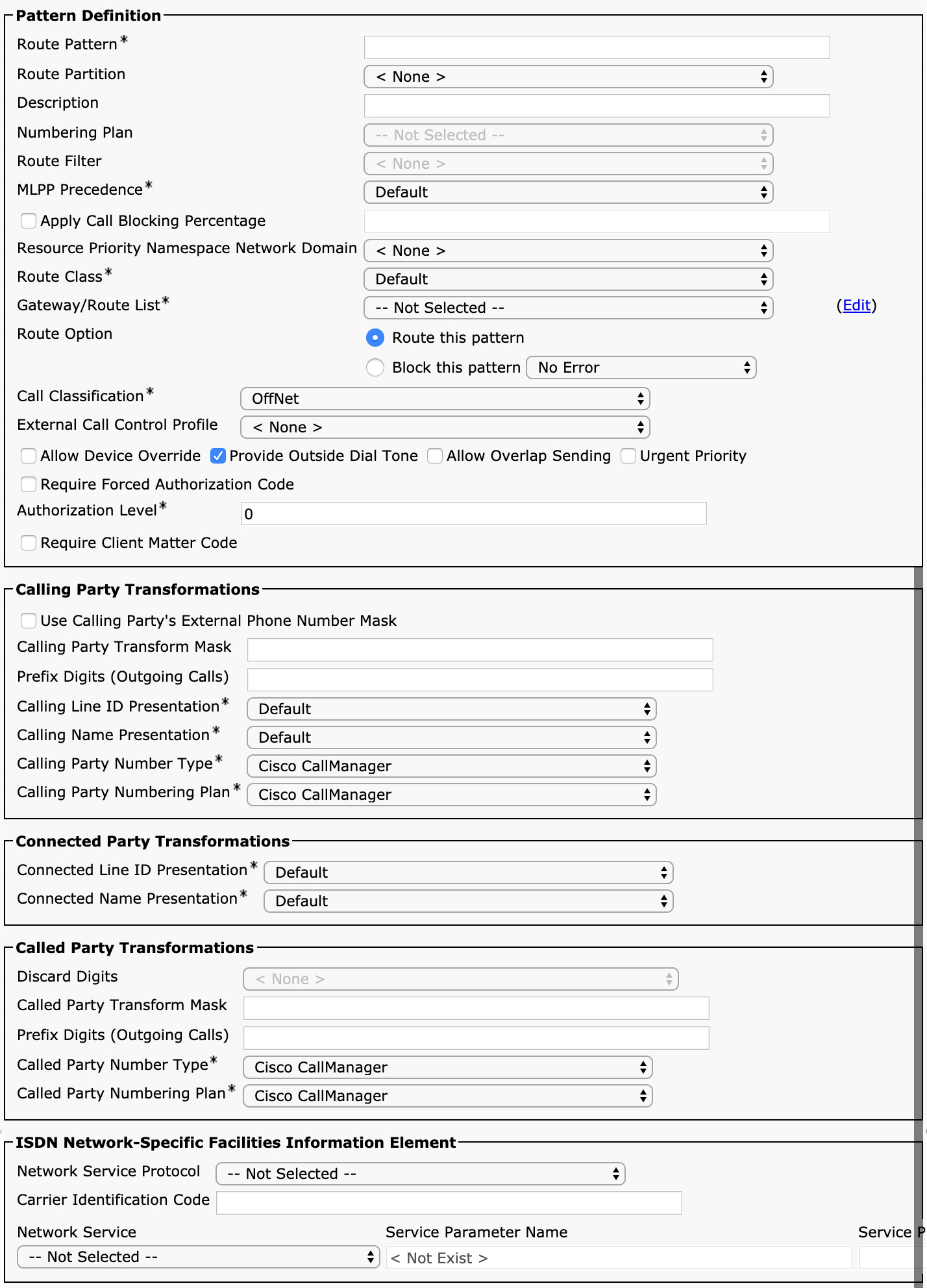
Figure 4-3 Route Pattern Configuration
You can see that there are many possible configuration options on this page, which can be a bit intimidating. However, as you will see, most of the options are self-explanatory. You will also see that there are many similarities between the configuration of a route pattern and the configuration of a translation pattern, covered later in this chapter.
The first parameter on the route pattern configuration page is somewhat confusingly named Route Pattern. Unified CM generally refers to patterns as route patterns and also has a specific configuration element called a route pattern. This book uses the term pattern to refer to the generic use of the word route pattern (as it appears as the label for the first parameter on this configuration page) and uses the term route pattern to denote the dial plan element called the route pattern configuration (shown in Figure 4-3). The Route Pattern field on the route pattern configuration page allows you to specify the pattern you would like to be matched. A route patterns typically contains a pattern with wildcards, as these patterns typically match large ranges of directory numbers. (However, route patterns do not always have wildcards.)
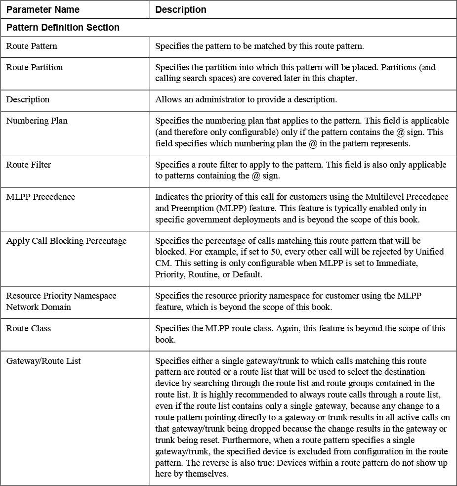
Table 4-5 describes each of the fields on the route pattern configuration page and the function of each parameter. If you are unfamiliar with any of the fields on the route pattern configuration page, you should read through the table because you will see that most of these parameters apply to other dial plan elements, such as translation patterns and calling/called number transformation patterns, discussed later in this chapter.
![]()
Table 4-5 Parameters on the Route Pattern Configuration Page
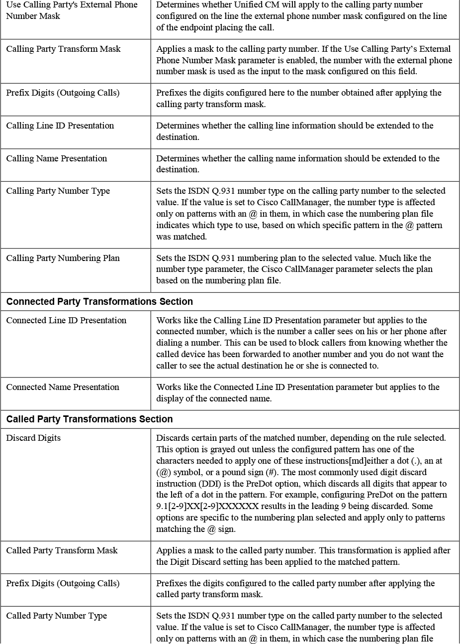
You will notice that after matching a route pattern, you have quite a bit of flexibility to modify both the calling and called party numbers. Be aware that transformations made on a route pattern could have some unintended consequences. First of all, any transformations of the called party number will be reflected (at least temporarily) on the phone of the user placing the call. For example, if you configure a PreDot digit discard instruction on a pattern 9.[2-9]XX[2-9]XXXXXX and a user dials 99195551234, the user’s phone display changes to indicate that the number 9195551234 has been called. You will see, however, that additional dial plan elements may change this again.
When in doubt about a setting in the Unified CM Administration user interface, remember that you can select Help > This Page to get to a built-in guide with many definitions specific to the page currently being viewed.
![]()
The second idiosyncrasy to keep in mind with transformations on a route pattern is that any transformation done on a route pattern will be completely replaced by transformations performed on a route list, as discussed shortly. The transformations on a route list start from the original calling/called party numbers, not the output of the transformations on the route pattern. Because of these caveats, it is often preferable to not use the transformations on the route pattern configuration page and rather use the similar configuration options provided on the route group details configuration on the route list.
If the route pattern configuration page indicates a gateway or trunk as the destination, the call is routed immediately to that single gateway or trunk. There is no additional failover that occurs if the call fails to be extended on the specified gateway or trunk. To be able to route calls across multiple gateways or trunks to balance the load across multiple trunks or to provide resiliency in the event that one or more gateways or trunks fail, you must leverage route lists and route groups.
Route Lists
A route list allows you to specify an ordered list of route groups to which to route a call. The route groups specified in a route list are always used in a top-down order. This means that as long as the devices within the first route group in a route list are working, that route list will receive all of the calls until all of the devices within that route group fail or run out of capacity, at which point the next route group in the route list is attempted. This continues until the call succeeds or until the end of the list is reached. If Unified CM fails to extend a call to any of the route list entries, it generates a RouteListExhausted alarm and alerts to tell the administrator that the system was unable to extend a call on a particular route list. This could be because all the trunks are busy and there is no capacity, because there is a failure to connect to the trunk destination, or because the far end of the gateway or trunk is returning a failure cause when the call is extended.
Configuring a route list involves two distinct configuration pages. First is the route list configuration page, where you specify the name and a handful of parameters along with the list of route groups you want to include in the route list. The second configuration page is the route group details for each route group configured in the route list. In other words, for each route group you add to a route list, you can specify transformations specific to that route group when used as part of this particular route list.
Figure 4-4 shows the main route list configuration page in Unified CM which can be accessed from Unified CM Administration > Call Routing > Route/Hunt > Route List.

Figure 4-4 Route List Configuration Page in the Unified CM Administration User Interface
You can see that there are very few settings on this page. However, there are some important concepts related to how these parameters work that you need to understand—especially the significance of the Cisco Unified Communications Manager Group setting.
By default, a single route list process is created on one node of a multi-node Unified CM cluster. That one node is responsible for handling all calls destined to that route list. The Cisco Unified Communications Manager Group setting specifies the list of servers where the route list process for this route list may run. It runs on the first server in the group that is available. The Registration field indicates which server in the cluster is currently running the route list process for this route list. If you see the route list showing up as Unregistered, click the Reset button at the top of the page to restart the process. The Run On All Active Unified CM Nodes checkbox changes this behavior. Instead of running on a single server, when this parameter is selected, each server in the cluster runs a copy of the route list process for this route list. There are several advantages to doing this, mainly the ability to better balance load across the cluster because each server can handle processing of route list events instead of relying on a single server. This improves troubleshooting because data related to a single call is more likely to be all on the same server instead of being spread out across many different servers in the cluster. The recommendation is to always use the Run On All Active Nodes parameter to achieve the best load balancing and make troubleshooting easier.
Before we discuss the route list details for each route group, you need to understand some additional parameters that determine when Unified CM hunts to the next route group and when it stops routing altogether. If a call connects, a route list does not attempt to reroute the call, even if there is some failure after the call connection. Connecting a call stops the route list hunting process. For call failures during the attempted call establishment, Unified CM usually extends the call to the next device within a route list’s route group; however, there are four service parameters that control the routing behavior for specific types of call failure scenarios. These are found under Unified CM Administration > System > Service Parameters > Server > Cisco CallManager, in the section Clusterwide Parameters (Route Plan). You must click the Advanced button at the top of the page to see the fourth parameter, as it is hidden by default. These four service parameters specify whether Unified CM should stop routing or continue attempting additional route groups and devices configured as part of those route groups after receiving specific cause codes.
![]()
The first is the Stop Routing on Out of Bandwidth Flag parameter. By default, this is set to False, which means if a call is attempted and the reason the call was not extended is a cause code indicating that there is not sufficient bandwidth to complete the call, Unified CM continues to route to the next route group member. The naming of these parameters can be somewhat confusing. When Stop Routing on Out of Bandwidth Flag is set to False, it indicates that you do not want to stop. In other words, it means you want continue in this scenario.
The next parameter is Stop Routing on Unallocated Number Flag. This parameter is set to True by default, which means if a call is attempted to a gateway or trunk and the cause code returned when a call is extended indicates the number is unallocated (for example, Q.850 cause code 1 or a SIP 404 response), the route list does not continue hunting; the assumption is that if the number does not exist on one trunk, it won’t exist on any of the other trunks configured.
The third parameter is Stop Routing on User Busy Flag. This parameter is also set to True by default, to stop routing calls if the returned cause code indicates that the user is busy (for example, Q.850 cause code 17 or a SIP 486 response). Again, the reasoning is that if a user is busy when dialed on one trunk, sending the call via a different trunk a few milliseconds later will likely not be useful because the user is still probably busy.
The final parameter, which you can see only if you click the Advanced button at the top of the page, is the Stop Routing on Q.931 Disconnect Cause Code parameter, which allows you to specify one or more cause codes, separated by spaces. Remember that by default, Unified CM continues routing on any cause code other than unallocated number and user busy, based on the two parameters mentioned previously. If you would like Unified CM to stop routing on any other cause code, you must specify it in this field.
You should be very careful about using these parameters. They are global in nature and therefore apply to calls on all route lists and route groups configured on the cluster. You might, for example, try to use one of these parameters to force a call to route or not route based on a specific issue, but there can be unintended consequences of doing so because the change affects other gateways or trunks on the system.
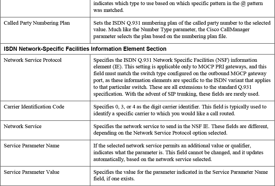
Now that you understand the ordered list of route groups in a route list and the logic used to determine whether to continue hunting for another route group, you should understand the route list details configuration that can be applied to each route group in the route list. For each route group that is added to a route list, there is an entry in the Route List Details section at the bottom of the route list configuration page, as you can see back in Figure 4-4. If you click on any of the entries that appear on that section, you see the route list member configuration screen, as shown in Figure 4-5.
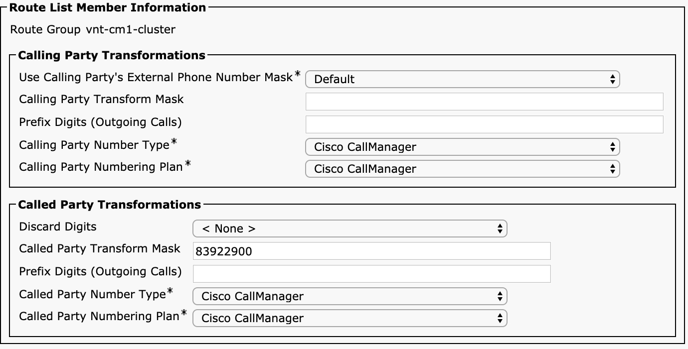
Figure 4-5 Route List Details Configuration Page in the Unified CM Administration User Interface
This page should look familiar because the entries are a subset of the Calling Party Transformations and Called Party Transformations sections of the route pattern configuration page. These transformations work identically to those for route pattern configuration, so if you have a question about how any of them work, refer to Table 4-5. The only parameter that is different is the Use Calling Party’s External Phone Number Mask setting, which is a selection menu instead of a checkbox. On the route list details configuration, there are three settings: Default, On, or Off. As mentioned earlier, any transformations applied on the route list details completely replace any transformations done on the route pattern. Selecting Default indicates to use the setting configured on the route pattern, and selecting On or Off replaces the setting with what has been configured.
If Use Calling Party’s External Phone Number Mask is changed from Default or if anything is configured in the Calling Party Transform Mask or Prefix Digits (Outgoing calls) fields, the original calling party number gets the new transformations applied. Similarly, in the Called Party Transformations section. Any configuration in this section supersedes the settings that were applied on the route pattern. One setting worth pointing out is the difference between < None > and NoDigits for the Discard Digits parameter. If set to < None >, the configuration on the route pattern applies. If set to NoDigits, no digits are discarded, and the settings on the route list details override the called party number transformations on the route pattern.
Also note that any transformations performed on the called party number on a route list do not affect the display of the dialed number on the IP phone placing the call, whereas transformations on the route pattern do affect the display. Later processing still has the potential to update the called or connected party number, but the route list transformations do not.
Route Groups
A route group is a collection of one or more gateways or trunks that are used to route a call. Route groups are configured in Unified CM Administration > Call Routing > Route/Hunt > Route Group (see Figure 4-6).

Figure 4-6 Route Group Configuration Page in the Unified CM Administration User Interface
In the first section of the route group configuration page, you can specify the name of the route group as well as the distribution algorithm. There are only two choices: Top Down and Circular. As the names imply, the Top Down setting tries each gateway or trunk in the route group, always starting with the first available entry on the list. For gateway devices where Unified CM knows the active call state for each port or channel, such as MGCP or SCCP voice gateways, Unified CM starts hunting from the first available or non-busy port when set for Top Down. For gateway or trunks where Unified CM does not know whether capacity is available—for example, for H.323 or SIP gateways—Unified CM assumes that all gateways are available and hunts through them as if they all have available capacity. In the event of a call failure, such as a SIP 500 Internal Server Error response, during call setup, the route group continues to hunt through the list of devices until the call is successful or until all entries in the route group are exhausted.
Top Down behaves the same way a hunt list behaves. In fact, you may have a hard time deciding whether to create several route groups with one gateway each and put those route groups into a route list in the desired order or put all the gateways and trunks into a single route group set for Top Down. These two options behave identically. The main reason you might want to break things up into more than one route group is if you need to apply different transformations to different sets of trunks because the route list details apply to all gateways and trunks in a route group.
The Circular setting provides some level of round-robin load balancing by starting the hunt sequence from a different member each time the route group is used. For example, if a route group is configured for circular distribution, and it contains three trunks, named A, B, and C, the first time the route group is used, Trunk A is used first. The second call that uses the route group starts on Trunk B. The next call is extended to Trunk C. The next call again starts from Trunk A, and the process repeats. If all ports are busy on a trunk or if a call fails during setup, the next trunk is used. Let’s use the second call on this trunk as an example: If the call establishment fails across Trunk B, Trunk C is next up for the call, and Trunk A is last if the call also fails across Trunk C. This mechanism should provide for reasonably even distribution between devices in the route list. As you will see in Chapter 5, SIP trunks can also provide load balancing and redundancy by allowing for multiple destinations on a single trunk.
By combining route lists and route groups, you can load balance calls among a set of trunks or gateways. Then, only when all those routes are exhausted or fail, you can move on to a second set of devices by having a second route group in the route list. Note that the Stop Routing On… service parameters described earlier apply to route groups as well. Unified CM stops routing through a route group if one of the Stop Routing On… cause codes applies, and subsequently it does not move on to the next entry in the route list. For example, if a call returns a 404 Not Found with the Q.850 Cause Code 1, indicating an unallocated number, Unified CM checks the Stop Routing on Unallocated Number service parameter to determine what to do next. If this parameter is set to True, Unified CM stops routing and fails the call; if it is set to False, Unified CM continues to the next available device in the route group.
Local Route Group
The combination of route pattern, route list, and route group offers a flexible set of tools for an administrator to route calls to external devices and achieve load balancing and redundancy, but you may have noticed that the three dial plan elements are strongly tied to each other. Say that the administrator of a company with 4000 remote branches wants to configure a pattern for users to dial a PSTN number by dialing 9.1[2-9]XX[2-9]XXXXXXX and then match a route list, which sends the call out through a centralized SIP trunk, but if that call fails, try to send the call out through a local gateway at the branch. With the dial plan elements we have discussed so far, the administrator would have to configure 4000 route patterns, each of them pointing to 1 of 4000 route lists, each of which contains the route group with the central SIP trunk followed by the local gateway for that site. This means configuring 4000 route patterns, where the only difference is the route list, and configuring 4000 route lists, where the only difference is the second route group that appears in the list. Certainly, there must be a better way! This type of deployment challenge is what led to the development of the dial plan element called the local route group. This feature, initially introduced in Unified CM Version 7.0, was enhanced with the multiple local route group feature in Version 10.5; it gives administrators a way to address the situation where route patterns, route lists, and route groups are identical with the exception of the route groups being different, depending on some criterion such as the location, branch, or site.
![]()
The local route group allows an administrator the ability to place a generic placeholder in a route list instead of in a specific route group. The local route group then abstracts a specific route group from the call routing logic and allows an administrator to assign a location-specific route group that will be used in its place. Because the multiple local route group feature has been available since Version 10.5, we discuss this more advanced version. (Prior to Version 10.5, however, everything works exactly the same way except that there is only a single local route group available.)
When using a local route group, instead of specifying the Branch 1234 Local Gateway route group, an administrator can add a more generic Branch Local Gateway route group to a route list. In this case, Branch Local Gateway is not the name of a route group but rather it is the name of a placeholder. The actual route group used is determined by the configuration on the device pool of the calling device. This means that you can change what Branch Local Gateway means for a particular device by changing the local route group configured on the device pool for this device.
The original local route group feature had only one such placeholder, named Standard Local Route Group. The name was not configurable, and only one local route group could be configured on the device pool. Thanks to the introduction of the multiple local route group feature, you now have additional flexibility. To see how this is configured, start with the configuration for the local route group names by navigating to Unified CM Administration > Call Routing > Route/Hunt > Local Route Group Names. Figure 4-7 shows an example of this configuration page.
Figure 4-7 Local Route Group Names Configuration in the Unified CM Administration User Interface
In the example shown in Figure 4-7, you can see that there are three local route groups configured: Emergency PSTN Route, Priority 1 PSTN Route, and Priority 2 PSTN Route. These are just arbitrary names selected by an administrator who wants to control how emergency calls and other PSTN calls are routed. You can click the Add Row button to add as many local route group names as you would like. It is unlikely that you will ever need to create more than a handful of them, however. By default, Unified CM comes with a single local route group named Standard Local Route Group, but you can rename it to be anything you want; however, you must always have at least one local route group configured.
Once a local route group name has been added to the local route group names configuration page, these names appear in the route list configuration page, alongside all your other (real) route groups. You can use this route group the way you would any other route group, with the distinction being that the actual route group used will depend in the calling device’s device pool. To configure the actual route group, navigate to Unified CM Administration > System > Device Pool. In the device pool configuration page is a section labeled Local Route Group Settings that shows a list of the local route groups you added earlier. By default, all the local route groups on a device pool are set to < None >. If a local route group is set to < None > on the device pool of a calling device and a call is placed through a route list containing that local route group, it is as if the route group is not configured on the route list at all. This by itself does not cause an error and in some cases may be a desired configuration if there are other route groups in the route list available to handle the call.
Hunt Pilots, Hunt Lists, and Line Groups
Route patterns, route lists, and route groups are used to distribute calls to other systems external to Unified CM. Hunt pilots, hunt lists, and line groups are used to distribute calls to groups of IP phones registered to a Unified CM cluster. In some ways, they behave similarly: Hunt pilots are similar to route patterns, hunt lists are similar to route lists, and line groups are similar to route groups. However, there are also several differences worth discussing. As with route patterns, route lists, and route groups, the configuration order is the reverse of the order discussed here: You must configure hunt groups first, then add them to hunt lists, and then use a hunt list on a hunt pilot.
Line Groups
The first element you must configure is the line group. A line group allows you to group a series of lines on phones into a group for the purposes of distributing calls in some fashion to those lines. Figure 4-8 shows the line group configuration page, which can be found by navigating to Unified CM Administration > Call Routing > Route/Hunt > Line Group.

Figure 4-8 Line Group Configuration in the Unified CM Administration User Interface
There are a variety of parameters you can configure for a line group. One of them is RNA Reversion Timeout (where RNA stands for ring no answer). This determines how long this line group will ring a line or group of lines before attempting another group.
The Distribution Algorithm parameter determines how calls are distributed between the members of the line group. There are four options:
![]()
• Top Down: The devices in the list will always be tried starting from the first and hunting sequentially through the list.
• Circular: The devices on the list will be selected in a round-robin fashion.
• Longest Idle: The device on the list that has been idle for the longest period of time will be selected.
• Broadcast: The call will ring all the devices in the line group simultaneously, and the first device to answer will accept the call.
The Hunt Options settings determine how Unified CM treats no answer, busy, or unregistered conditions of line group members. For each of those three conditions, you can select one of the following options:
• Try next member; then, try next group in Hunt List: This is the default value. If a member meets the condition (no answer, busy, or not available/unregistered), it is just skipped.
• Try next member, but do not go to next group: If a member meets this condition, other members in the group are attempted, but the next group in the hunt list (if there is another group after this line group) will not be used.
• Skip remaining members, and go directly to next group: If the selected condition is met, no other members of this line group are used, and Unified CM moves on to any subsequent line groups that appear in the hunt list.
• Stop hunting: If the condition is met, no further members are selected from the line group or hunt list, and the call fails.
Unified CM allows for users to be either logged in or logged out of a line group either through administrative configuration or a softkey or button on the phone that controls whether a user is logged in or out of configured line groups. In the case of no answer, you can optionally enable the checkbox Automatically Logout Hunt Member on No Answer, which does exactly what the name implies. This means you can avoid continuously ringing a phone where someone has stepped away without logging out manually. A user must then manually log back into the hunt group to receive new calls by using the configured hunt group login softkey, or an administrator may log a phone back in to a hunt group by checking the Logged Into Hunt Group value on a phone configuration page in the Unified CM Administration user interface.
Once you have selected all the distribution and hunting options, the only thing left to do is add the lines to the line group. The list of lines shown in the Selected DN/Route Partitions list is an ordered list, although the order generally only applies to the Top Down distribution algorithm.
Hunt Lists
After you have created a line group, you can add it to a hunt list. A hunt list is very similar to a route list. To configure a hunt list, navigate to Unified CM Administration > Call Routing > Route/Hunt > Hunt List. Figure 4-9 shows the hunt list configuration page.
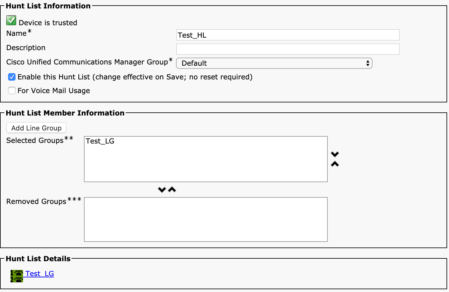
Figure 4-9 Hunt List Configuration in the Unified CM Administration User Interface
The configuration of the hunt list is relatively straightforward. You just need to provide a name, select an option for Cisco Unified Communications Manager Group, and add groups. You should check the box to enable the hunt list, and if the hunt list is being used to extend calls to Unity Connection or another voicemail system, you should select the For Voice Mail Usage checkbox.
If you check the For Voicemail Usage check box, the route list control process keeps a count of the setups that are being served to the hunt list and does not allow more setups than the number of available devices. This prevents Unified CM from sending more calls than the voicemail system can receive.
The list of line groups in the hunt list is ordered and is always processed top-down, starting with the first line group in the list and moving down the list based on the hunt options that configured on the line group. Each line group’s hunt options determine whether and when the next entry in the hunt list is chosen. Unlike with route lists, there is no special transformation or configuration on a per-line-group basis on the hunt list configuration.
Hunt Pilots
The final step needed to get line groups to work is to create the hunt pilot. A hunt pilot is similar to a route pattern, but it contains additional configuration to deal with forwarding and queueing of calls. Figure 4-10 shows the pattern definition section of the hunt pilot configuration, which can be found by navigating to Unified CM Administration > Call Routing > Route/Hunt > Hunt Pilot.

Figure 4-10 Hunt Pilot Configuration in the Unified CM Administration User Interface
You can see that this part of the configuration is very similar to the route pattern configuration. The biggest difference is that you can specify a hunt list instead of a route list. A hunt pilot also allows you to configure a call pickup group. (This feature is discussed in Chapter 6.) Finally, the configuration allows you to specify an alerting name, which is what calling phones see on the display when they call the hunt pilot before a line group member answers the call.
The interesting part of the hunt pilot configuration is the Hunt Call Treatment Settings section, shown in Figure 4-11.
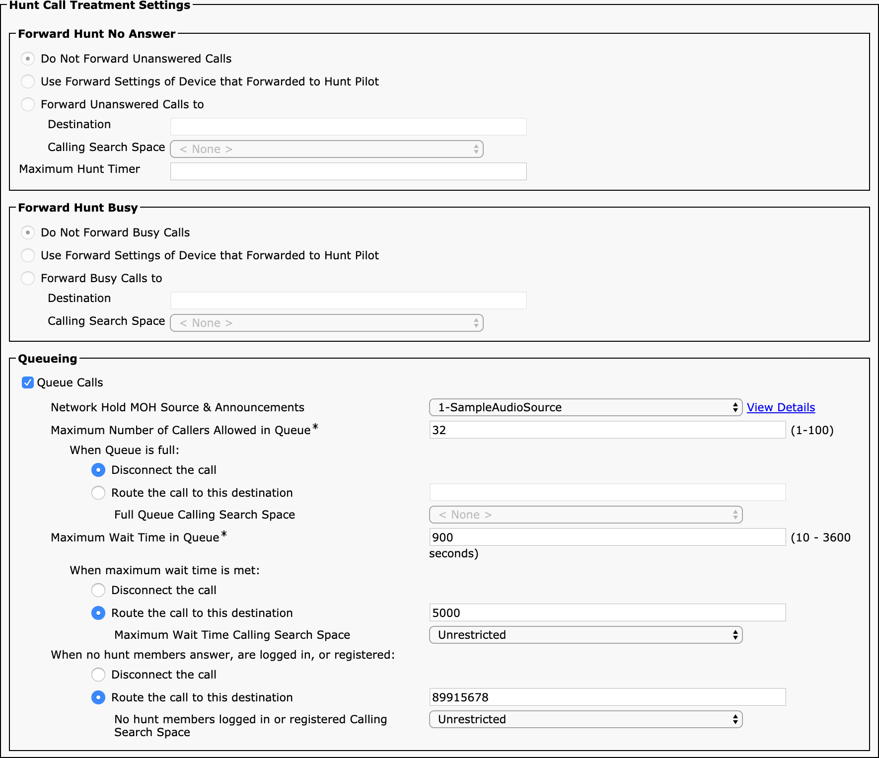
Figure 4-11 Hunt Pilot Hunt Call Treatment Settings in the Unified CM Administration User Interface
You have two options, which are mutually exclusive: You can choose to either use call forwarding on busy and/or no answer on the hunt pilot, or you can enable queueing. If you select the Queue Calls checkbox, the forwarding settings are disabled.
By default, calls are not forwarded or queued, so if all hunt list and line group members are exhausted, the call fails. If you choose to invoke forwarding, you can do so for calls that are unanswered or calls where all the members are busy. If you select the option Use Forward Settings of Device That Forwarded to Hunt Pilot, the Call Forward No Coverage setting on the forwarding device is used. Otherwise, the page allows you to specify a phone number and a calling search space to use. (Calling search spaces are covered in the next section.) You can also specify the maximum hunt timer, which determines how long a call to this hunt pilot will attempt to ring devices before forwarding to the no answer destination.
If you want to be able to have callers put into a queue instead of being forwarded when all members are busy or not available, you can enable queuing with the Queue Calls checkbox. When queuing is enabled, you have a variety of options. First, you must select the music on hold audio source as well as the maximum number of calls to allow into the queue. If the queue reaches the limit, you have the option to either disconnect the call or have the call forwarded to another destination—perhaps a voicemail box number or some other recording that tells the users the system is busy. You can also specify a maximum time to wait in queue, at which point the When Maximum Wait Time Is Met parameter is invoked to either disconnect the call or forward it to another destination.
The last parameter in this section allows you to determine what happens if none of the members answer the call or if no members are registered.
The remainder of the hunt pilot configuration is identical to the route pattern configuration page, allowing you to add calling and called party number transformations. These are generally not used often because the calls are being extended to phones rather than being sent over a trunk.
![]()
After having configured route patterns, route lists, route groups, hunt pilots, hunt lists, and line groups, you might be wondering if there is a way to get a visualization of how these elements tie together. The Route Plan Report page, available from Unified CM Administration > Call Routing > Route Plan Report allows you to search for numeric or alphanumeric patterns and view a quick snapshot of the configuration. Figure 4-12 shows an example of this page.
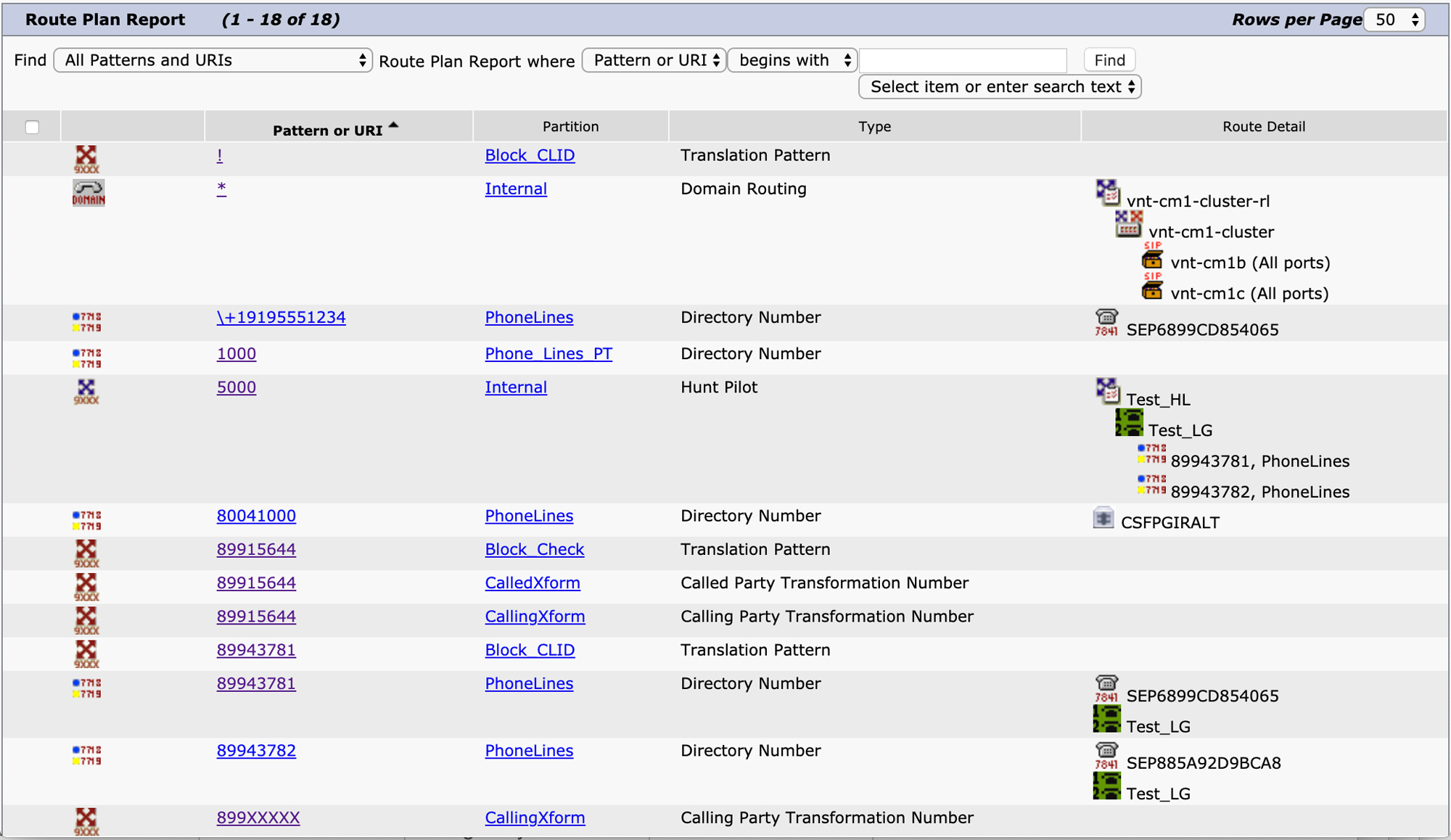
Figure 4-12 Route Plan Report
You can see in the figure that each route pattern shows the route list, route groups, and trunks or gateways associated with that pattern, and a hunt pilot shows the hunt list and line group members. The Route Plan Report pages provides a very convenient way of quickly searching for configured dial plan elements.
The hunt pilot configuration pages have several areas where you have to select a calling search space, and the following section covers this topic.
Partitions and Calling Search Spaces
Several of the configuration pages you have already seen allow you to configure a route partition, but up until now, we have glossed over what this is and how it works. Partitions and calling search spaces work together to provide some of the most flexibility in your dial plan design. Administrators new to Unified CM sometimes find understanding partitions and calling search spaces confusing, but this is likely due to not having the concept explained properly. In reality, partitions and calling search spaces are simple, but you can use these simple constructs to build complex dial plans.
![]()
At a high level, partitions and calling search spaces allow an administrator to create groups of patterns, whether they be route patterns, directory numbers, numbers associated with features, alphanumeric URIs, or any other dial plan element that can be called. These groups of patterns are called partitions. A calling search space is simply a list of partitions that a calling device or feature can look at to find a match for a number. To be more specific, a calling search space is actually an ordered list of partitions, but you will soon realize that the order of partitions in a calling search space is often irrelevant. A partition is assigned to anything that can be called, and a calling search space is assigned to anything that needs to look for a number to call or invoke a feature.
Any time a pattern is configured in Unified CM, it must be placed into a partition. By default, a pattern is placed into the < None > partition. This is a special default partition that exists on a fresh installation and cannot be removed. As a general best practice, you should never use the < None > partition because patterns in the < None > partition can be reached by any device or feature on the system: Every calling search space, including the < None > calling search space, has access to the < None > partition.
To configure a partition, navigate to Unified CM Administration > Call Routing > Class of Control > Partition. A partition has only one required configuration parameter: a name. You can also configure an optional description when first creating a partition. After you add a partition, you can modify it by adding a time schedule, as discussed later in this chapter.
A partition should contain groups of patterns that are equally reachable by a calling entity. For example, you might want to have a partition for all the directory numbers in your cluster. This assumes that all directory numbers are equivalent from an authorization perspective—in other words, a user or device authorized to reach the directory numbers partition can place a call to all directory numbers. If you have some specific requirement to restrict calls to certain directory numbers from certain phones, you might need to create a separate partition to hold the restricted directory numbers.
The calling search space configuration is found under Unified CM Administration > Call Routing > Class of Control > Calling Search Space. To create a dial plan in Unified CM, you have to leverage various partitions and calling search spaces to break apart the pieces of your dial plan to restrict access to certain patterns so that only authorized users can reach them. You might also need to rely on partitions and calling search spaces to handle location-specific differences; for example, what it means to dial a local number in one area could be very different from what it means in another area, or national dialing could be completely different in clusters handling calls for phones in several different countries.
To begin, an administrator might want to add the ability for phones to place calls to other phones or place emergency calls but not have the ability to place any outbound PSTN calls. Figure 4-13 shows a very basic dial plan with two partitions: one with all directory numbers and another with the route patterns for emergency calls.
Figure 4-13 Partition and Calling Search Space Example for Internal and Emergency Dialing
All the directory numbers on phones are in the Phone_Lines_PT partition. Route patterns used to reach emergency numbers are in the US_Emergency_PT partition. Why not put all of these patterns in the same partition? The reason is simple. Perhaps you want to later create a calling search space where a phone can only dial other phones but cannot place emergency calls, or vice versa—where a phone can only place an emergency call but cannot call other phones in the system. By breaking the patterns into separate partitions, you have the flexibility to mix and match which partitions are contained in a given calling search space.
To expand on this dial plan and add the ability for certain phones to place local PSTN calls, you might add another partition with additional route patterns and a new calling search space, as shown in Figure 4-14.
Figure 4-14 Partition and Calling Search Space Example for Local PSTN Dialing
The NC_919_984_Local_PT partition contains patterns to dial local calls in the 919 and 984 area codes, which correspond to central North Carolina in the United States. This partition and the previously discussed partitions are added to a new calling search space, the NC_919_984_Local_Calling_CSS calling search space. A device assigned to this calling search space will be allowed to call other phones, make emergency calls, and place local PSTN calls.
Next, you might want to permit certain phones to dial long-distance calls in addition to local calls. In that case, you need to add additional route patterns and place them in yet another partition. Figure 4-15 shows the addition of two new partitions and a new calling search space that permits national calling.
Figure 4-15 Partition and Calling Search Space Example for National Dialing
This figure shows the two new partitions that have been added and added to the newly created NC_919_984_National_Calling_CSS calling search space. The US_National_PT partition contains patterns allowing access to any PSTN number in North America for calls that are considered long-distance calls. Because of the way the North American Numbering Plan (NANP) works, several countries all share the same country code, so the patterns in the US_Block_CC1_Intl_PT partition is used to add blocking patterns that block calls to area codes that are considered to be international calls. These are all route patterns configured with Block This Pattern on the route flag. In a real deployment, there would be many more of these patterns—one for each area code in Canada and the Caribbean.
The NC_919_984_National_Calling_CSS calling search space permits a calling device to place calls to on-cluster directory numbers, emergency calls, PSTN calls to the local area codes 919 and 984 by using 10-digit dialing, and calls to national numbers in the United States with the exception of those area codes considered to be international calls. Figure 4-16 shows the configuration page for the NC_919_984_National_Calling_CSS calling search space.

Figure 4-16 Configuration of NC_919_984_National_Calling_CSS Calling Search Space
You might have noticed that the route pattern 9.1[2-9]XX[2-9]XXXXXX overlaps with the pattern 9.1242XXXXXXX. If someone dials a number such as 9 1 242 555 1234, which of these route patterns is matched? The 9.1242XXXXXXX pattern is matched because it is a better or closer match, based on the closest-match routing rules discussed earlier in this chapter. You may be tempted to think that the order of the partitions in the calling search space would factor into this equation, but it does not. This is a key point to understand. The order of partitions in a calling search space does not matter—with one exception. The order matters only if there are two equivalent matches found in different partitions. In the case where there are two equivalent matches, the pattern in the highest partition in the list is chosen. If the call fails when routed to this pattern, it does not use any other equivalent matches in another partition.
Finally, if you want to add a calling search space that permits international calls, you can add one more partition and create a new calling search space that includes the new partition, along with the internal, local, and national PSTN patterns mentioned before. Figure 4-17 shows the partitions and calling search space needed to enable international calling.
Figure 4-17 Partition and Calling Search Space Example for International Dialing
The US_International_PT partition contains patterns that allow for calling to international locations, and this partition is included in the international calling search space. Notice that the NC_919_984_International_Calling_CSS calling search space does not include the US_Block_CC1_Intl_PT partition, which is used to block international calls that look like U.S. national calls. A phone in this calling search space would be allowed to call these numbers because they are international numbers, so they do not need to be blocked.
When you put everything together, you end up with the relationships of partitions and calling search spaces shown in Figure 4-18, which is a full example of the five partitions and four calling search spaces described previously to create a simple dial plan with class of service restrictions.
![]()
Figure 4-18 Partition and Calling Search Space Example
You can see how the relationships between partitions and calling search spaces are a many-to-many relationship. Calling search spaces can contain many different partitions, and a partition may appear in more than one calling search space. This allows you a great deal of flexibility in designing your dial plan.
![]()
One last item to note regarding calling search spaces is the interaction of calling search spaces configured on a phone device and the lines associated with that phone. You can configure a calling search space on a phone, and you can configure calling search spaces on a line. If you place a call from a line on a phone, which calling search space gets used? The answer is both. Unified CM concatenates the list of partitions in the line calling search space with the list of partitions in the device calling search space (in that order) and then searches for a match in the full list. Remember that the order matters only when there are equal matches, so if a partition that is part of the device calling search space contains a the best match for a dialed number, it is matched even if there is a less-specific match on the line calling search space.
Time of Day Routing
As mentioned earlier, partitions allow you to assign a time schedule to a partition. A time schedule contains a list of time periods. Figure 4-19 shows a configuration example for a time period named Work Day that includes the times from 9 a.m. to 6 p.m. on Monday through Friday.
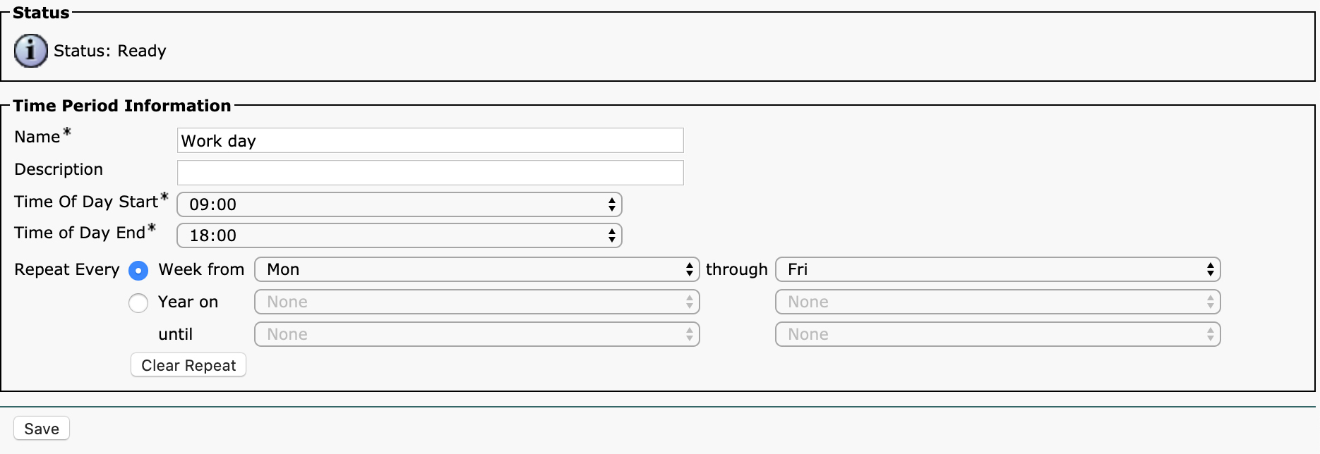
Figure 4-19 Work Day Time Period Configuration Example
This time period can then be added to a time schedule, as shown in Figure 4-20.
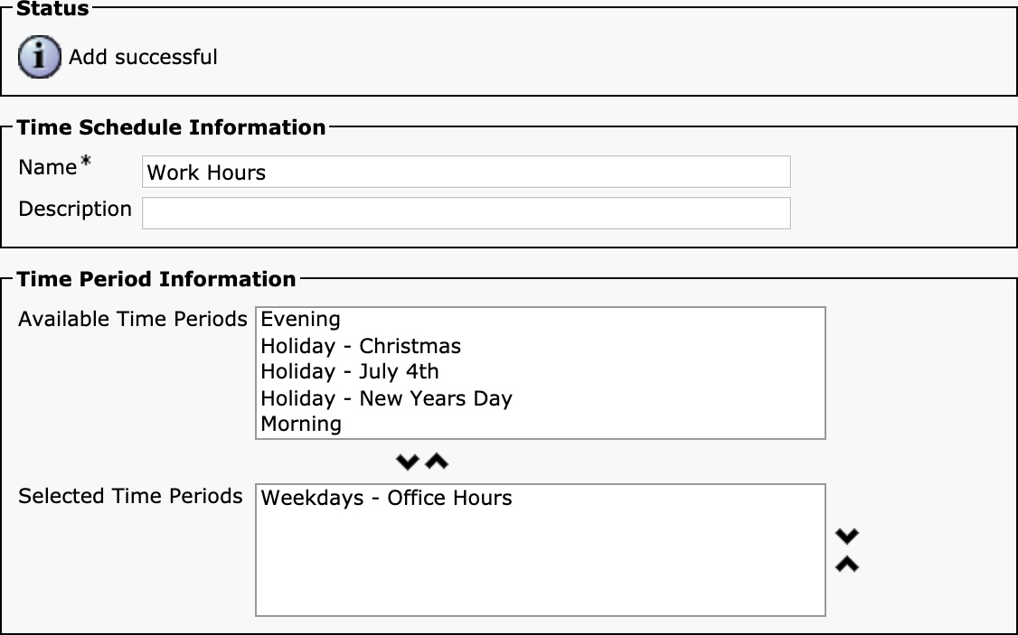
Figure 4-20 Work Hours Time Schedule Configuration Example
The time schedule can include more than one time period. For example, you might create a time period for each holiday and then create a time schedule named Holidays that includes all the holiday time periods.
Once you have created a time schedule, you can apply it to a partition. For example, if you want to restrict international calls to be allowed only during work hours for the dial plan presented earlier, you can apply the Work Hours time schedule to the US_International_PT partition. When a time schedule is applied to a partition, that partition exists only during the time periods added to the time schedule. Outside those times, it is as if the partition and all the patterns contained in that partition do not exist. Figure 4-21 shows the configuration of a time schedule on a partition.
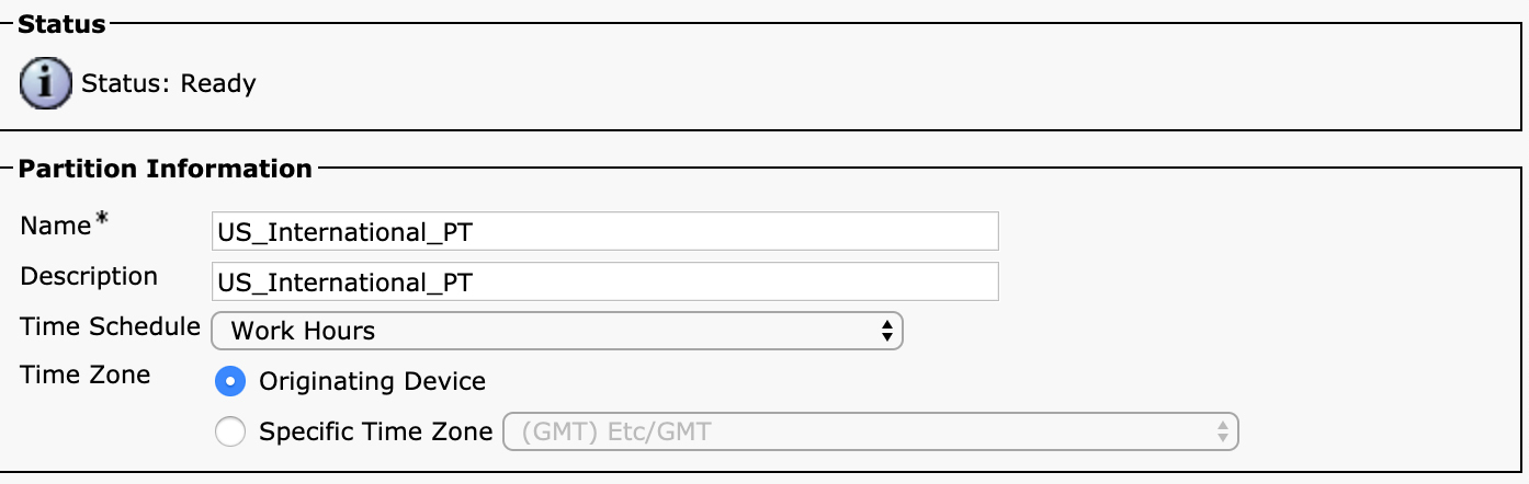
Figure 4-21 Work Hours Time Schedule Added to a Partition
Notice that the configuration for a time schedule also has a selection for a time zone. This selection is important because it determines the time zone that will be considered when evaluating a time period. For example, if a time period allows calls from 8 a.m. to 6 p.m., what time zone are those times in? The selection on the partition configuration page allows you to either select the time zone of the originating device or select a specific time zone. If you select a specific time zone, the partition is active for the same periods of time, regardless of what device is placing the call. If Originating Device is selected, then the time zone will come from the date/time group assigned to the device pool on the originating device.
So far in this chapter you have learned the basics of partitions and calling search spaces. It is important to remember that partitions contain patterns or numbers that can be dialed, and calling search spaces contain the partitions to look through when a device or feature needs to look up a number. The complexity in partitions and calling search spaces mainly comes from the sheer number of places in the Unified CM Administration user interface where you can configure calling search spaces. Understanding the purpose of each calling search space configuration field can be difficult, but you can simply remember that they all do the same thing: provide a list of partitions to search through for a pattern. One area where the intricacies of calling search spaces comes into play is with translation patterns, discussed next.
Translation Patterns
Translation patterns are some of the most powerful call routing tools at your disposal as an administrator. Understanding all the various parameters available to you in a translation pattern can help you build complex dial plans. At first glance, the configuration for a translation pattern looks almost identical to the configuration for a route pattern—and for good reason: Most of the configuration parameters for a translation pattern are identical to and serve the same purpose as those on the route pattern configuration page. Before we discuss how you configure a translation pattern, you need to understand the purpose of a translation pattern and how it fits into a dial plan.
A translation pattern works very similarly to a route pattern in that you configure a pattern to match, and that pattern is placed in a partition, like any other callable number in Unified CM. This means that a device with a calling search space that contains the partition in which the translation pattern is configured can dial a sequence of digits to match the configured pattern on the translation pattern. The difference is that instead of routing the call to a route list or gateway/trunk, a translation pattern reroutes the call back to the digit analysis engine and performs a new digit analysis lookup after applying whatever calling and called party transformations were configured on the translation pattern. In order to perform a new search through digit analysis, the translation pattern has a calling search space that is used to perform the new search after the configured transformations. It is as if a new call were to have been placed, but instead of using the calling search space configured on the device or feature invoking the call, the calling search space is replaced with the one configured on the translation pattern.
Figure 4-22 shows the translation pattern configuration page, which can be found by navigating to Unified CM Administration > Call Routing > Translation Pattern.
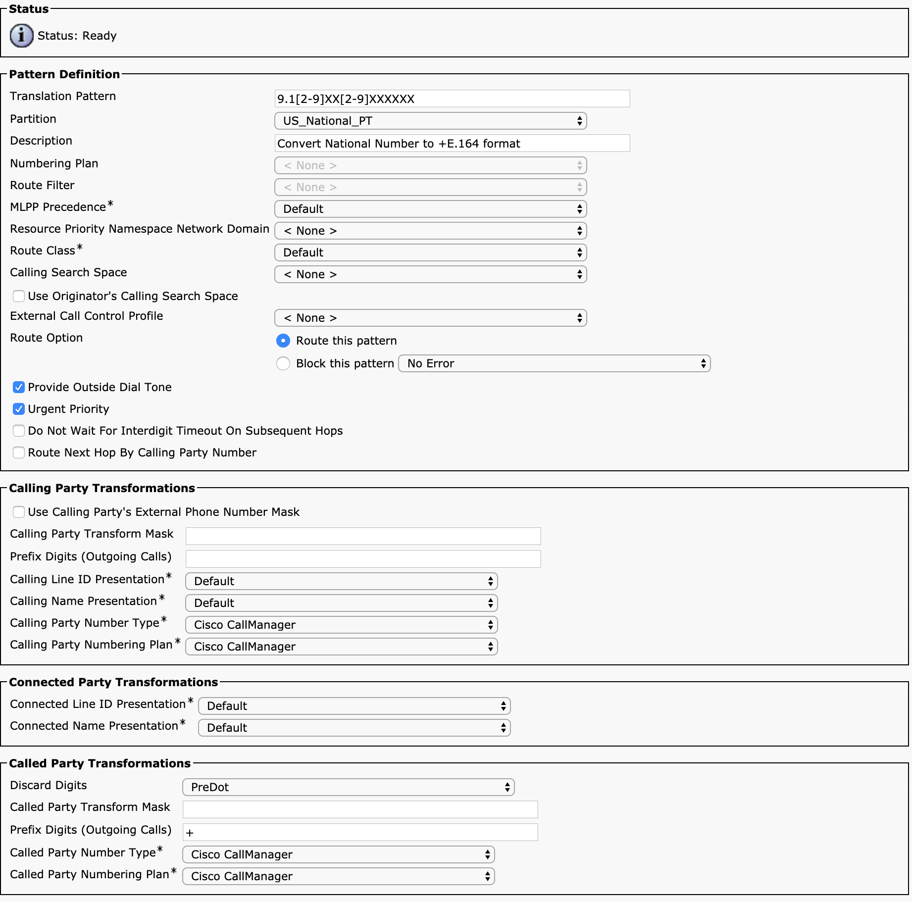
Figure 4-22 Translation Pattern Configuration in the Unified CM Administration User Interface
Recall that Table 4-5 describes all the parameters on the route pattern configuration page. Most of the parameters on the translation pattern configuration page are identical to those described in Table 4-5, so they are not repeated here. Instead, we focus on the parameters that differ from those for the route pattern configuration.
The biggest difference that you will notice is that a translation pattern does not have a Gateway/Route List parameter but instead has a Calling Search Space parameter to specify the calling search space to be used to route the call after the transformations have been applied by the translation pattern.
Figure 4-23 shows an example of how a translation pattern can be used to covert a phone number dialed by a user as a 7-digit local phone number into +E.164 format before routing the call to the PSTN.
![]()
Figure 4-23 Example Translation Pattern Call Routing Flow
Notice that the user dials 9 followed by a 7-digit number: 9 555 1234. The calling search space on the user’s phone or line contains the Local_AC_919 partition, which contains the translation pattern 9.[2-9]XXXXXX. If this translation pattern is the best match in all the partitions that appear in the phone’s calling search space, it attempts to translate the number and search for another match. In this case, the translation pattern first applies a calling party number transformation which indicates that the external phone number mask configured on the line should be used. This means the mask +1984555XXXX is applied to line 1000 to convert the calling party number to +19845551000. Second, a called party transformation pattern is applied to the number: +1919XXXXXXX. This means that, for this example, the called party number is transformed to +19195551234. This new calling and called party number is then passed back to the digit analysis engine, using the calling search space configured on the translation pattern—Full_PSTN_Access—and a new route lookup is performed.
The Full_PSTN_Access calling search space contains a partition named PSTN_Routes, which contains the route pattern +!. The new called party number that was created by the translation pattern matches this route pattern, and the call routes through the appropriate route list.
Notice that the IP phone does not have direct access the +! pattern because the phone does not have the PSTN_Routes partition in its calling search space. However, the call eventually does use this route pattern to route the call. Translation patterns allow you to access other partitions in a restricted fashion, as highlighted in this example.
![]()
There are several other configuration parameters on the translation pattern configuration page that differ from the parameters for a route pattern. For example, if the Use Originator's Calling Search Space checkbox is selected, the Calling Search Space field is disabled. By checking this box, you tell the translation pattern to use the calling search space of the device/feature that originated the call. If the originating device is an IP phone, the combined list of partitions from the line and device calling search spaces that were used to originate the call is used. This capability gives you additional flexibility by allowing you to create a translation pattern that strictly transforms the calling/called party number but does not affect which calling search space the user has access to. This means you can use this checkbox to create a translation pattern that is broadly used across a variety of devices; where the call gets routed after the transformations depends on the calling device.
The next parameter that appears on the translation pattern configuration page that is not found on the route pattern configuration page is the checkbox Do Not Wait for Interdigit Timeout on Subsequent Hops. This checkbox can be useful as you can prevent a user from having to wait for interdigit timeout after dialing a number if you know there should be no further digits provided. In the example shown in Figure 4-23, when the dialed number was translated to +19195551234, it subsequently matched the route pattern +!. This route pattern is a variable-length route pattern, so even though the full number has already been provided by the translation pattern and no further digits are expected, Unified CM still waits for the interdigit timeout because the +! pattern can accept additional digits. To avoid having to wait for the interdigit timeout, the translation pattern shown in Figure 4-23 should also have the Do Not Wait for Interdigit Timeout on Subsequent Hops checkbox selected so that the call routes immediately. This is also typically used on any translation pattern with the Trailing-# digit discard instruction configured. The pound sign is commonly used to indicate that no further digits are coming, and translation patterns are often used to remove this pound sign before routing a call to its ultimate destination, but this setting can ensure that after matching the pound sign, the system does not wait for further digits.
The final checkbox that is new on the translation pattern page is the Route Next Hop By Calling Party Number checkbox. This is an unusual selection that temporarily changes the way pattern matching works in Unified CM. If this box is selected, after the calling and called party numbers have been transformed, Unified CM searches for a match by using the calling party number, not the called party number. Note one very unusual behavior when using this feature: If the next hop that is matched is a route pattern, the called party number remains as the calling party number that was used to match the route pattern, and therefore, the outbound call setup contains what was originally the calling party number as the called party number. This behavior is rarely desirable. Typically, when this feature is used, the subsequent hop is another translation pattern that does not have Route Next Hop By Calling Party Number selected, in which case the proper called party number once again becomes the called party number to extend the call. This checkbox is typically used to block calls from specific phones and other PSTN sources based on the calling party number.
Besides the parameters mentioned in this section, all the other parameters on the translation pattern configuration page are identical to those configured for a route pattern. One behavior difference worth mentioning, however, is that changes made on a translation pattern become the “original called party number” and “original calling party number” for the purposes of any modification done on a route list. Recall that modifications done on the route list details for a specific route group override any changes made on the route pattern configuration. This is not the case for changes made on a translation pattern. If a call passes through a translation pattern before reaching a route pattern, any changes done on a route list apply to the numbers after translation pattern transformations are applied.
As if all this talk of transformations on translation patterns and transformations on route patterns and route list details for route groups weren’t confusing enough, there is yet one more dial plan element remaining to cover: the transformation pattern.
Transformation Patterns
One of the possible challenges that the local route group feature introduces is the inability to perform calling or called number transformations on a per-route-group basis. With a normal route group, you can manipulate calling and called party numbers by using the route list details configuration to modify numbers on a per-route-group basis, but with a local route group, these transformations apply to all the route groups configured as a local route group. For example, if you have route groups named Branch 0001 PSTN through Branch 2000 PSTN assigned as the local route group named Branch PSTN on 2000 different device pools and you have a single route list that contains the Branch PSTN local route group, any transformations you perform on the route list details for the Branch PSTN local route group will be applied to all 2000 route groups when they are used as part of this route list. If you want to be able to manipulate digits differently, depending on which of the branch PSTN routes you take, you must resort to transformation patterns.
There are two types of transformation patterns: calling party transformation patterns and called party transformation patterns. As you might imagine, calling party transformation patterns allow you to manipulate the calling party number, and called party transformation patterns allow you to manipulate the called party number. Other than this distinction, they operate in nearly the same way. The key to understanding transformation patterns is understanding how they are configured and how they get used.
Up until now, patterns have been configured on dial plan elements that can be called—such as on a directory number, a route pattern, or a translation pattern—and these patterns are all placed into a partition that is reachable through one or more calling search spaces. Transformation patterns follow a similar paradigm, but they are not something you can call, although they can be “looked up” by Unified CM as part of the call routing process. How that lookup occurs is controlled by a calling search space that works similarly to when a call is placed, as you will see.
Transformation patterns should look very familiar to you because the parameters configurable on transformation patterns are a subset of the parameters available on a translation pattern. For example, Figure 4-24 shows the configuration page for a calling party transformation pattern. You reach this page by navigating to Unified CM Administration > Call Routing > Transformation > Transformation Patterns > Calling Party Transformation Pattern.

Figure 4-24 Calling Party Transformation Pattern Configuration in the Unified CM Administration User Interface
As you can see, you can configure a transformation pattern just the way you configure a route pattern or translation pattern, and you can place the pattern into a partition. All transformation patterns are considered to be urgent priority because they are not matched digit-by-digit the way that other patterns are matched, so although the Urgent Priority checkbox appears on the screen, it cannot be deselected. Other than that, the other parameters behave the same as the ones you already know about. When you configure the calling party transformation patterns, you must place them into a partition. It is recommended that you create separate partitions and calling search spaces for your calling and called party transformation patterns, although technically they could live alongside other patterns, such as route patterns and directory numbers. However, when configuring a calling search space that looks for calling party transformation patterns, none of the other pattern types are considered.
Figure 4-25 shows the configuration for a called party transformation pattern, which can be found by navigating to Unified CM Administration > Call Routing > Transformation > Transformation Patterns > Called Party Transformation Pattern.
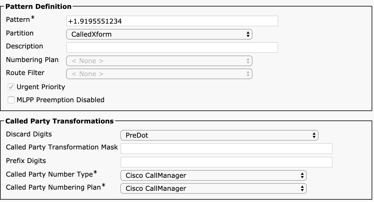
Figure 4-25 Called Party Transformation Pattern Configuration in the Unified CM Administration User Interface
In the same way that calling party transformation patterns are placed into a partition, called party transformation patterns are also placed into a partition. Again, it is suggested that you keep each transformation type in its own partition, which in this case means having a partition that contains only called party transformation patterns (or multiple partitions that contain only called party transformation patterns if you need to perform different types of transformations based on the outbound trunk or device).
Transformation patterns get applied after a pattern has been matched (either directory number or route pattern, after possibly going through one or more translation patterns) and the call has been extended to either a phone, gateway, trunk, or remote destination profile. Each of these device types offers various parameters that allow you to apply transformation patterns. This is all done by using special calling search spaces that are configured on the device. Each calling search space looks for either calling or called party number transformation patterns and looks for a match to transform a number based on that calling search space. The sheer number of places where these calling search spaces are available is what causes the most confusion, especially for calling search spaces with names that do not make it clear what kind of transformation patterns apply. Figure 4-26 shows a portion of the SIP trunk configuration page in the Unified CM Administration user interface.
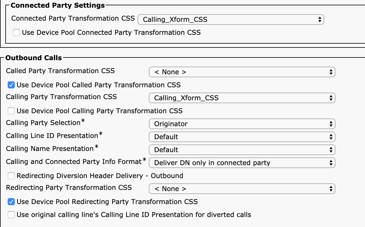
Figure 4-26 Transformation CSS Configuration on a SIP Trunk in the Unified CM Administration User Interface
In this figure, you can see eight transformation pattern–related parameters. There are four calling search spaces you can configure:
• Connected Party Transformation CSS
• Called Party Transformation CSS
• Calling Party Transformation CSS
• Redirecting Party Transformation CSS
For each of these calling search space selections, you have the checkbox Use Device Pool <x> Transformation CSS, were <x> matches the name of the calling search space from the previous list. (For example, you can enable or disable the Use Device Pool Called Party Transformation CSS checkbox.) Each of the checkboxes determines whether the calling search space configured on the device should be used or whether the applicable calling search space configured on the device pool in which this device has been configured should be used.
Note
You may already be confused upon seeing this list because we have only discussed calling party and called party transformation patterns but not connected party or redirecting party transformation patterns. This is because there is no such thing as a connected party or redirecting party transformation pattern. Both of these parameters also look for calling party transformation patterns. The only one that looks for called party transformation patterns is the Called Party Transformation CSS parameter.
![]()
It is important to understand what each of these calling search spaces does and which numbers they apply to. The first is the Called Party Transformation CSS. The calling search space configured here should contain a partition that contains called party transformation patterns. The called party number that gets sent to the gateway will be used to search for transformation patterns. One very important point to note is that transformation patterns search for the original called party number, not the number after any transformations are performed on a route pattern or route list details. This point cannot be stressed enough. The route pattern transformations and route list details are completely overwritten if a transformation pattern matches and the number that is used to look for a match is the original called party number, not the transformed number. You need to couple this with the fact that transformations performed on a translation pattern create a new “original” calling and called party number, so if a call passes through one or more translation patterns before matching a route pattern, the output of the last translation pattern matched is what is used as the input to any transformation patterns.
The best way to drive this point home is through an example. Imagine that a user dials 1000, which matches the translation pattern 1XXX. This translation pattern is configured to transform the called party number with the mask 2XXX, and the resulting called party number is 2000. Using the calling search space on the translation pattern, a match is found for a route pattern 2XXX, which is configured to route the call to a route list. On the route pattern, you configure the called party transformation mask 3XXX. On the route list that matches, in the route list details for a route group, you configure the called party transformation mask X5XX. This route group matches a SIP trunk with a called party transformation calling search space configured. In that calling search space, you have the following called party transformation patterns configured:
• 1XXX transforms the called party to 1111.
• 15XX transforms the called party to 1555.
• 2XXX transforms the called party to 2222.
• 25XX transforms the called party to 2555.
• 30XX transforms the called party to 3333.
• 35XX transforms the called party to 3555.
What will be the called party number when the call is presented to the destination of the SIP trunk? What if there is no called party transformation calling search space configured on the trunk?
![]()
Let’s walk through the process. When the user dials 1000 and the first translation pattern, 1XXX, is matched, it transforms the called party number to 2000. This now becomes the new original called party number and is used for the next digit analysis lookup. The new called number, 2000, now matches the 2XXX route pattern, which transforms the called party number to 3000. The route pattern points to a route list, and the route list details say to apply the called party transformation X5XX. Does this become 3500? No, it does not. Remember that the route list details override any transformations performed on the route pattern and transform based on the original called party number. Since the user dialed 1000, would this transformation become 1500? Again, no, it will not because the translation pattern creates a new original called party number, so at this point, the called party number becomes 2500. Now the call is routed to the trunk for routing. There is a called party transformation calling search space configured on the trunk with the patterns listed. Which (if any) pattern is matched, and what would the transformed number be? You might be tempted to think it would match 25XX, which would output 2555 as the called party number, but that is incorrect. Transformation patterns only look at the original called party number, but the original called party number was changed by the translation pattern, so the number that is searched for a match is 2000 (the called party number that matched the route pattern). Therefore, the final called party number sent out in the SIP INVITE is 2222, after matching the 2XXX transformation pattern.
Figure 4-27 should help you visualize the called party number at various stages and which numbers are used in the transformations at each stage.
Figure 4-27 Called Party Transformation Logic
What if there is no called party transformation calling search space configured on the trunk? In this case, the called party number would be 2500 because it would use the transformation that was applied by the route list details configuration. Figure 4-28 provides a visual example of how this works.
Figure 4-28 Called Party Transformation Logic Without Transformation Patterns
Note
If you are not 100% confident in the explanation for this example, please reread it as many times as necessary to make sure you understand it fully. If you understand this, you will have a good grasp of how transformation patterns work and the order of operations and precedence with transformations in various call routing elements. In fact, if you have a Unified CM cluster at your disposal, configure the example in some test partitions and calling search spaces and observe what happens. Also remember that although these patterns do not affect the routing of the call through Unified CM because they get applied after the destination device has been selected, they can affect the eventual routing of the call because the transformation modifies the number sent to the far-end system on the SIP trunk.
Although this example has examined called party number transformation patterns, the same process applies to calling party transformation patterns. Calling Party Transformation CSS allows you to select which calling party transformation patterns are searched by a match on the original calling party number. If there is a match, the calling party number is changed as the call is routed out through the trunk. This does not affect call routing but does affect number presentation of the calling party number.
The other two transformation calling search spaces, connected and redirecting, do not apply to the calling or called party number, but they still both leverage the calling party transformation to find potential matches and apply transformations to the connected number and redirecting number.
The third transformation calling search space is the Connected Party Transformation CSS. Although not visible in Figure 4-26, the Connected Party Settings section of the configuration is found under the Inbound Calls section of the configuration. This indicates that this calling search space only applies to calls arriving from an external device. This calling search space allows you to manipulate the connected number. By default, without any kind of transformation, Unified CM transmits the directory number of the device that was called as the connected party number so that the caller sees the number of the device that answered the call. This is not always the same as the number dialed to reach that device. Connected Party Transformation CSS allows you to transform that connected number (the number of the device that answered the call) as the connected number is being transmitted back to the originator of the call.
The final transformation calling search space is the Redirecting Party Transformation CSS. This calling search space is also in the Outbound Calls section of the configuration and applies to calls that are being sent out through the trunk and contain a redirecting party number (for example, if the call has been forwarded prior to being directed to the trunk). By default, the redirecting party number is the directory number of the line that redirected the call. This calling search space can look through calling party transformation patterns for a match and transform the redirecting number before sending the call out through the trunk.
Trunks are not the only location where you can configure transformation calling search spaces. The phone configuration page contains two calling search spaces that can be used to match calling party transformation patterns. They affect the way the calling party number is presented on a phone as well as manipulate the calling party number for calls placed from the phone. Figure 4-29 shows the configuration options on the phone configuration page, which you reach by navigating to Unified CM Administration > Device > Phone.

Figure 4-29 Transformation Calling Search Spaces on a Phone Configuration
The first transformation calling search space shown in this figure is in a section labelled Caller ID for Calls from This Phone. The directory number configured on the phone is used to search for a match for a calling party transformation pattern for all calls originating from this phone. You might wonder why this parameter exists if there are already options to provide an external phone number mask on a line and use that when routing a call through a route pattern or translation pattern. The reason is that there are situations with alphanumeric URI-based dialing in which a call is routed without ever touching a translation pattern or route pattern that would normally apply the external phone number mask to globalize the calling party number. (This is discussed later in the chapter, when we go into more detail on intercluster alphanumeric dialing.) This calling search space allows the administrator to configure transformation patterns that manipulate the calling party number for all outbound calls, even if they do not go through some other dial plan element that allows for the modification of the calling party number.
The second parameter on this page is in a section titled Remote Number. This calling party transformation calling search space affects how the remote calling party number is displayed on the phone’s display to the user receiving an inbound call. The transformation performed by the remote number, however, does not affect the number stored in the phone’s call history. Because this does not modify the call history, an administrator has the flexibility to provide a calling party number to a phone’s display in a globalized format that is familiar to the user while still retaining other modifications to the calling number that show up in the call history on the IP phone. One example of modifying the calling number for the call history is to append a 9, 91, or + to ensure that the call history on the phone matches the dial plan for outbound calls. With this in place, an end user can simply select a number from the call history without needing to perform extra modifications, such as adding a 9, 91, or +.
Note
The 9, 91, or + prefix applied to the calling party number is usually achieved by performing a calling party modification on the inbound gateway or trunk, which in turn affects how the number is displayed in the call history on the endpoint that ends up receiving the call. General design best practice is to globalize the number into +E.164 format instead of prefixing a steering digit such as a 9.
Another type of device that allows an administrator to configure a transformation calling search space is the remote destination profile configuration page, found in Unified CM Administration > Device > Device Settings > Remote Destination Profile. Remote destination profiles are discussed in Chapter 7, “Unified CM Mobility.” As you will learn in that chapter, this feature allows calls to an IP phone to simultaneously ring a mobile device. The calling party transformation calling search space configured on a remote destination profile allows you to manipulate the calling party number for calls destined to a remote destination. Again, these transformation patterns are needed because a call from a phone calling another phone on the cluster does not pass through a route pattern or translation pattern, so this is an opportunity for an administrator to manipulate the calling party number to ensure that it is properly presented to the PSTN. These transformations can be used to globalize the calling party number, and when the call is routed out to the PSTN to reach the mobile device, it can be localized by the transformation patterns configured on the trunk or gateway.
Transformation patterns are the final piece of the puzzle you can use to create complex dial plans in Unified CM. To put all the parts together, a real-world example is provided in the next section.
Putting It All Together: Tail-End Hop Off (TEHO)
Tail-end hop off (TEHO) is often configured in large, multinational companies as a way of leveraging corporate WAN links to save on international (or sometimes national) toll costs. The concept of TEHO is straightforward: Route a call out through the gateway or trunk where the PSTN costs for that call are the lowest. This typically means sending a call originating in one country through a gateway sitting in a different country—usually the one where the called party resides. For example, if a user in the United States places an international call to a user in the United Kingdom, instead of sending the call out through a local trunk in the United States as an international call, the system sends the call sent over the corporate WAN to a gateway or trunk in the United Kingdom, where it is sent as a local call. This, of course, assumes that the company has trunks or gateways in the United Kingdom. The opposite can also be configured, so that a user in the United Kingdom placing a call to the United States egresses through a U.S.-based gateway or trunk, thus avoiding any international toll call fees.
The TEHO process requires careful manipulation of calling and called party numbers to ensure that calls can be routed and formatted correctly for the PSTN provider receiving the calls. Also, in such a situation it is desirable to be able to attempt the call through alternate routes if the TEHO call fails without the user having to do anything special. The user should just be able to dial the number as if she were dialing an international call, and the system should handle any and all transformations necessary to route the call correctly.
In this section we go through a small subset of a much larger dial plan that shows how to configure TEHO for calls from the United States to the United Kingdom. These same concepts can then be applied to add other destinations or countries.
For this example, we assume that a user in the United States is required to dial a 9 to place a call to the PSTN and is using the standard North America dialing habit requiring the digits 011 to indicate an international call, followed by the country code and national number. For completeness, we also want the user to be able to optionally dial a pound sign (#) at the end of the digit sequence to route the call immediately instead of waiting for interdigit timeout.
Assume this customer has a SIP trunk to a PSTN provider in the United Kingdom, two SIP trunks in U.S. data centers, and a SIP trunk to a local PSTN gateway at each of 100 branch offices. For calls to the United Kingdom, the customer would like calls to first route over the WAN to the SIP trunk in the United Kingdom. If that fails, the call should attempt to use the SIP trunks in both data centers. If these three options are exhausted, the call should egress through the local gateway in the branch where the originating phone is registered.
The called party and calling party numbers must be formatted differently, depending on which outbound trunk is used, because the different PSTN providers are expecting the numbers in different forms. Figure 4-30 shows how the calling party number needs to be modified depending on the trunk or gateway used for the call.
Figure 4-30 TEHO Call Routing
As you can see in the figure, the user dials 9011441632960286# to reach the mobile number 01632960286 in the United Kingdom. If the call egresses through the PSTN in the United Kingdom, the called party number must be 01632960286 because the PSTN provider is seeing this as a local call and requires a leading zero. The two SIP trunk providers in the centralized data centers in the United States will accept the international call in +E.164 format (+441632960286), and the local PSTN gateways at the branches might have different requirements, based on the PSTN provider at that branch, so you should provide some level of flexibility to manipulate the called number differently, depending on the branch, but for the one branch you care about here, the number must be sent as 011441632960286.
![]()
Where do you start in building the dial plan to meet these requirements? First, the general best practice is to take the approach where any number dialed by the user is converted to a globally unique format that is independent of local dialing habits. In other words, regardless of whether a number is dialed in the United States, the United Kingdom, or China, the numbers dialed by the user should be converted to a common format. The well-established format for globalized phone numbers is the +E.164 format discussed in Chapter 1, “Introduction to Unified Collaboration and Dial Plans,” which consists of the plus (+) symbol followed by the country code and national phone number. Once the number has been globalized into +E.164 format, the call should be routed to the appropriate destinations by matching globalized patterns. Only when the call reaches the end device should the number be localized to meet the requirements of the system receiving the call. This globalization and localization should apply to both the calling and the called party numbers.
Figure 4-31 provides a high-level overview of the calling search spaces, partitions, route patterns, translation patterns, transformation patterns, route lists, and route groups needed to create the TEHO routing for calls from the United States to the United Kingdom. The details of the configuration of each item are discussed shortly.
Figure 4-31 TEHO Dial Plan Elements Overview
You can see six calling search spaces and six partitions for this example. The first two are for the translation and routing of the call, and the next four are for calling and called party transformations. You need to create the six partitions and then create the six calling search spaces that include those partitions. The first calling search space, International_With_TEHO_CSS, is the calling search space assigned to the phone placing the call. This calling search space allows access to the NANP_International_PSTN partition. In a real-world scenario, there would be other partitions that allow access to other patterns in addition to these international dialing patterns, but this section focuses specifically on the components needed to make this TEHO call work. This partition contains only translation patterns.
In order to globalize the calling and called party numbers, you should use translation patterns. The translation patterns will match the digits the user dials and then apply transformations to convert the localized numbers to +E.164 format. The first translation pattern shown in Figure 4-31 should be configured with the following parameters:
• Pattern: 9011.!
• Partition: NANP_International_PSTN
• Calling Search Space: Global_PSTN_Patterns_CSS
• Provide Outside Dial Tone: selected
• Calling Party Transformations:
• Use Calling Party’s External Phone Number Mask: selected
• Called Party Transformations:
• Discard Digits: PreDot
• Prefix Digits (Outgoing Calls): +
This translation pattern accepts calls dialed as 9 followed by 011 followed by the country code and number, strips off the 9011, and prefixes a + to convert the called number to +E.164 format. It also applies the calling party’s external phone number mask, which has been defined on the phone in +E.164 format already. In effect, this translation pattern converts both the calling and called party numbers into +E.164 format.
The second translation pattern is similar except it has the trailing pound sign, allowing a user to force the system to not wait for interdigit timeout. This translation pattern is configured as follows:
• Pattern: 9011.!#
• Partition: NANP_International_PSTN
• Calling Search Space: Global_PSTN_Patterns_CSS
• Provide Outside Dial Tone: selected
• Do Not Wait for Interdigit Timeout on Subsequent Hops: selected
• Calling Party Transformations:
• Use Calling Party’s External Phone Number Mask: selected
• Called Party Transformations:
• Discard Digits: PreDot Trailing-#
• Prefix Digits (Outgoing Calls): +
One difference between this translation pattern and the previous one is that Do Not Wait for Interdigit Timeout on Subsequent Hops is selected so that the subsequent match (which is the +! route pattern) does not have to wait for interdigit timeout. The other difference is that the digit discard instructions remove the trailing pound sign.
You might be wondering why the third and fourth translation patterns are needed since the patterns created so far already match the number in +E.164 format. These patterns are needed to ensure that the calling party number gets globalized. These patterns are configured as follows:
• Pattern: +!
• Partition: NANP_International_PSTN
• Calling Search Space: Global_PSTN_Patterns_CSS
• Calling Party Transformations:
• Use Calling Party’s External Phone Number Mask: selected
Finally, the last translation profile needs to be configured as follows:
• Pattern: +!#
• Partition: NANP_International_PSTN
• Calling Search Space: Global_PSTN_Patterns_CSS
• Do Not Wait for Interdigit Timeout on Subsequent Hops: selected
• Calling Party Transformations:
• Use Calling Party’s External Phone Number Mask: selected
• Called Party Transformations:
• Discard Digits: PreDot Trailing-#
Each of these translation patterns has the calling search space Global_PSTN_Patterns_CSS configured. This calling search space includes only the Global_TEHO_Patterns partition. In a real deployment, this calling search space would also include other globalized route patterns to reach other destinations, even if they are not TEHO sites. For the sake of this example, the partition includes only a single route pattern that matches calls to the United Kingdom (country code 44) and routes them to a route list. The route pattern is configured as follows:
• Pattern: +44.!
• Partition: Global_TEHO_Patterns
• Gateway/Route List: UK_DC1_DC2_LRG
Most of the parameters on the route pattern are left blank because there are no transformations being performed on the route pattern. Transformations to localize the number will be done either on the route list details for each route group or by using transformation patterns.
The route list contains three route groups, which will route the call to the U.K. PSTN trunk, the two centralized SIP trunks, and the local gateway, based on the local route group. From the point onward, you have several options for how to localize the number back to a form that the PSTN providers are expecting. You could use transformations on the route list details to perform the transformations, but this would cause problems for the local route group if you needed to apply different transformations at different branches that are using the local route group since the route list details configuration applies to the whole local route group.
Instead, you can use calling and called transformation patterns applied on the trunks or gateways. You need two sets of transformation: one to handle the calling and called party transformations for calls the egress through the U.K. PSTN and another set to localize the calling and called party numbers for egress through the U.S. PSTN. The first called party transformation pattern handles localization of the called party number for the United Kingdom:
• Pattern: +44.!
• Partition: UK_Called_Xform_CSS
• Called Party Transformations:
• Discard Digits: PreDot
• Prefix Digits: 0
As you can see, this transformation pattern would remove the +44 and prefix a 0 to make the called number compatible with the U.K. PSTN. This converts the number +441632960286 to 01632960286. This transformation pattern would then be applied to the U.K. SIP trunk because the called party transformation calling search space is set to UK_Called_Xform_CSS.
Next, configure the following calling party transformation pattern to transform the calling party number:
• Pattern: +.1!
• Partition: UK_Calling_Xform
• Calling Party Transformations:
• Discard Digits: PreDot
This transformation pattern may or may not work, depending on how the PSTN carrier in the United Kingdom handles calling number information. It is possible that the carrier will accept the calling party number in +E.164 format, in which case this transformation is not needed. It is also possible that the carrier will not accept an international number for the calling party number, in which case you may have to resort to masking the number with a phone number owned by your company in the United Kingdom so that the called party will at least receive a phone number indicating that the call is originating from your company. If you need to do this, you can add a calling party transformation mask on the calling party transformation pattern with the number you want to send any time a TEHO call originates from the United States. To apply these transformations to the calling party number, you set the calling party transformation calling search space on the U.K. SIP trunk to UK_Calling_Xform_CSS. Now calls dialed from the United States as international U.K. numbers will be routed via TEHO through the U.K. SIP trunk.
In case the call through the U.K. SIP trunk fails for some reason, the route list includes a second route group. Although not shown in Figure 4-31, this route group contains two SIP trunks: one in each data center. The provider for these two SIP trunks accepts the calling and called party numbers in +E.164 format, as shown in Figure 4-30, so for these two SIP trunks, no calling or called party transformation calling search space configuration is necessary.
If U.K. SIP trunk and both data center SIP trunks fail to route the call, the call is sent to the local gateway at the branch. This gateway is selected via the Local Route Group feature. Based on the device pool of the device, the route group that contains the gateway for that branch is selected. There are two more transformation patterns needed to convert the +E.164 format to a format expected by the local PSTN. Start with the called party number. The PSTN provider providing service to the local gateway you are interested in expects the calling and called party numbers to be in NANP format, which means the calling party number should be a 10-digit number, and the called party number should adhere to the standard NANP dialing habit. This means that for international calls, the number should be 011 + country code + national number. To transform the number, configure the following transformation pattern:
• Pattern: +.[2-9]!
• Partition: US_Called_Xform_CSS
• Called Party Transformations:
• Discard Digits: PreDot
• Prefix Digits: 011
Notice that this pattern matches anything that starts with a + followed by 2 through 9. This represents any call to an international destination from the perspective of a U.S.-based caller. The pattern strips the + and prefixes the 011. This means that the number +441632960286 becomes 011441632960286, which is what the local provider is expecting.
Finally, configure the following transformation pattern to deal with the calling party number:
• Pattern: +1.!
• Partition: US_Calling_Xform
• Calling Party Transformations:
• Discard Digits: PreDot
Notice the position of the dot (.) in this case. The PreDot instruction discards the +1, leaving the 10-digit national number as the calling party number. Once you have put all this together, you will have a flexible TEHO design for calls to the United Kingdom.
Hopefully you can see how this process can be easily extended to other countries as well. If you want to add another TEHO destination, you just need to add a few more patterns to deal with calls to that country; users across your enterprise can then make use of it.
Now that we have covered numeric dialing in depth, it is time to return to the topic of placing calls using alphanumeric URIs.
Alphanumeric URI Routing
Alphanumeric URI dialing is becoming increasingly common, thanks to the adoption of video endpoints and video-capable soft clients, especially in environments where business-to-business (B2B) calling is enabled through Cisco Expressway. Alphanumeric dialing allows for calling between endpoints using a URI that resembles an email address, such as [email protected].
We briefly discussed alphanumeric URIs at the beginning of this chapter. As a reminder, a URI has two distinct components that are separated by the @ sign. The component to the left of the @ is sometimes referred to as the left-hand side (LHS), or the user portion, and the component to the right is referred to as the right-hand side (RHS), or the host portion. Unified CM generally matches URIs based only on an exact match. If there is no exact match for a full URI, Unified CM tries to route the call based on the host/RHS portion of the URI only.
Figure 4-32 provides a flowchart that outlines the process by which Unified CM determines how to route a URI-based call.
![]()
Figure 4-32 URI Routing in Unified CM
Let’s walk through the flowchart. The first determination Unified CM makes when receiving a call in URI form is to check whether the user portion (LHS) of the URI is numeric (that is, only numbers). There is an asterisk next to that question in the flowchart because there is a caveat here: This decision is affected by the setting of the Dial String Interpretation parameter on the SIP profile of the calling device. There are three choices for this parameter:
• Phone Number Consists of Characters 0–9, *, #, and + (This is the default setting.)
• Phone Number Consists of Characters 0–9, A–D, *, #, and +
• Always Treat All Dial Strings as URI Addresses
The first option is the default setting, but if one of the other options is selected, then the “digits” ABCD are considered to be numeric or, in the case of the third option, the URI follows the NO path in the flowchart, regardless of whether the LHS is numeric. An additional caveat is that if the SIP request URI contains user=phone—for example sip:*[email protected];user=phone—Unified will treats the dialed string as a number, regardless of the Dial String Interpretation setting.
Let’s focus on the flow if the LHS is not numeric, which is the case for most alphanumeric URIs. The first thing that occurs is Unified CM searches for a match for the URI in the calling search space configured on the phone in the same way that it would search for a directory number or another pattern. URIs are configured on the directory number configuration page alongside the numeric pattern. In fact, you can configure up to five directory URIs on a directory number, and you can also configure Unified CM to automatically assign a directory URI to a line based on the directory URI configured on a user associated with the line, as shown in Figure 4-33.

Figure 4-33 Directory URIs Configured on a Line
You can see in the figure that the first URI in the list cannot be modified. This is because it is imported from the associated user. Notice that the partition for the imported directory URI is just named Directory URI. This partition comes preinstalled in the system and cannot be deleted. You can include this partition in any appropriate calling search spaces to allow users to dial URIs in those partitions or you can configure the Directory URI Alias Partition parameter in the Enterprise Parameters configuration page (Unified CM Administration > System > Enterprise Parameters). If you select a partition for this parameter, any imported directory URI in the Directory URI partition is automatically placed into the Alias partition. If you add a new URI, the partition in which the URI is placed is configurable, as it would be a directory number or for another pattern.
Also notice that there is an Advertise Globally via ILS checkbox next to each URI. Although we have not talked about ILS yet, it will be discussed in the next section. For now, just note the presence of this checkbox and know that it’s a good practice to leave it enabled, even in a single-cluster environment, in case you ever need to expand your network to replicate URIs to other clusters.
If the calling search space on the calling device does not have the partition with the URI being dialed or the URI doesn’t exist on the cluster at all, the call will move to the next step in the flowchart. If the URI is found in the calling search space, the call is extended to the device where the URI is configured.
It is important to note that URIs must be matched exactly as dialed to make a match—with one exception. By default, URI matching is performed in a case-sensitive manner. This means that if a line is configured as [email protected] and a user dials [email protected], the call will fail. Most administrators relax this policy to make URI matching case-insensitive so that [email protected], [email protected], and [email protected] all match the same URI ([email protected]). In order to enable case-insensitive matching, you must set the URI Lookup Policy enterprise parameter, configured under Unified CM Administration > System > Enterprise Parameters, to Case Insensitive.
The next step is to look to see if the URI matches one in ILS, which is discussed in the next section. This is the full list of URIs that have been replicated from other clusters in the enterprise. The mechanisms by which ILS works are covered shortly; for now just know that Unified CM stores a list of all the URIs on all other clusters, and each of those URIs is associated with a value called a route string that identifies how to reach the cluster that “owns” that URI. If an entry in the ILS database is found with an associated route string, Unified CM attempts to route the call by searching for a SIP route pattern that matches the route string.
SIP route patterns are configured in Unified CM from the Unified CM Administration > Call Routing > SIP Route Pattern configuration page (see Figure 4-34).
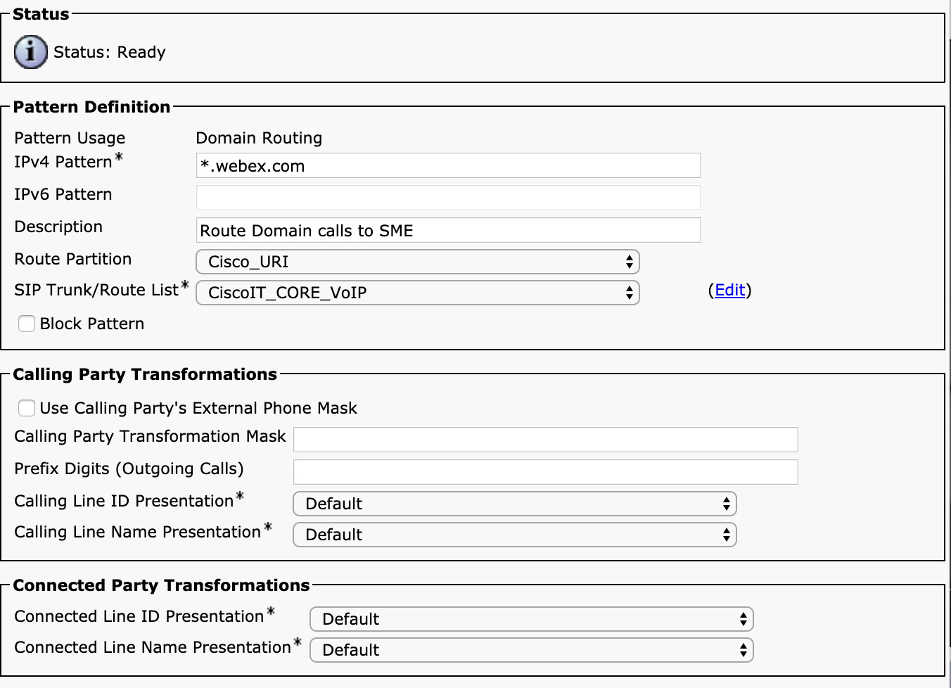
Figure 4-34 SIP Route Pattern Configuration
In this example, Unified CM is being told that any subdomain of the webex.com domain (for example, cisco.webex.com or example.webex.com) will match this pattern. A SIP route pattern is placed into a partition just as any other pattern would be, so a calling device must contain the partition in its calling search space in order to place a call through a SIP route pattern. All the other parameters should look familiar. Notice that there are no called party transformations. This is because you cannot do any kind of manipulation on URIs. When they are matched, they are always sent as matched. You can, however, manipulate the calling party number (not the calling URI, which is also sent as configured).
Notice that when Unified CM checked to see if a URI matched one in ILS, it did not check for a partition. This is because learned URIs are not placed into a partition. They all exist in a global table. The only way to restrict access to URIs is by restricting access to which SIP route patterns a user is allowed to reach. If the user’s calling search space cannot reach the partition of the SIP route pattern for the route string, the phone cannot call the URI. SIP route patterns match a route list or gateway device and route the call through the normal route list/route group/trunk logic as discussed earlier in this chapter.
If the URI is not found in ILS or if a SIP route pattern is not found for the route string, then the last thing Unified CM attempts to do is just look at the host portion (RHS) of the URI and attempt to match a SIP route pattern based on just the RHS. If a match is found, the call is routed to the destination specified by the SIP route pattern. Otherwise, the call fails.
If the LHS is numeric, Unified CM follows the bottom section of Figure 4-32. Patterns that are considered numeric based on the SIP profile configuration never attempt to match the full URI, either by looking for a matching directory URI on the cluster or by looking in ILS. Numeric patterns follow a completely different logic. The first step is to determine whether the RHS matches either the hostname, fully qualified domain name (FQDN), or IP address of any of the servers in the cluster or if the RHS matches the Cluster Fully Qualified DN (CFQDN) enterprise parameter. If either of these is true, Unified CM attempts to find a numeric match based on the LHS of the URI. If a match is found, the call is routed just as if that number had been dialed from a phone. If a match is not found, no further action is taken, and the call fails.
However, if the RHS does not match a cluster node address or the CFQDN parameter, Unified CM checks to see if the RHS matches the Organization Top Level Domain (OTLD) enterprise parameter. If it does match, it searches for a numeric match of the numbers on the LHS, but this time if there is no match, the call does not fail, and Unified CM looks for a SIP route pattern that matches the RHS of the URI. It also attempts to search for a SIP route pattern match if the RHS does not match the OTLD.
Now that you understand how URIs are routed in Unified CM, you should understand how to replicate URI information between different clusters so that users in different clusters can reach each other via URI dialing.
Intercluster Dial Plan Replication
Traditional URI dialing between enterprises has relied on routing based on the right-hand side of the URI. For example, if [email protected] wants to call [email protected], Alice’s Unified CM cluster just needs to know how to reach the sj-cucm.ccnpcollab.lab domain. It does not need to know whether [email protected] is a user. It is up to the call control device for the sj-cucm.ccnpcollab.lab domain to determine whether that URI is valid. In general, URI dialing is done based on the RHS of the URI.
How do you handle an enterprise with multiple call control devices (for example, Unified CM clusters) with users in the same domain—such as if [email protected] has a device registered to Unified CM Cluster A and [email protected] has a device registered to Unified CM Cluster B? How can you route calls between these two clusters? Well, if it’s just two clusters, you could have a “default route.” Basically, if Cluster A does not find a match for a user locally, then it can have a route saying to send all calls to the cisco.com domain to Cluster B. Cluster B can do the same, paying special attention to not loop a call back to Cluster A if it originated from Cluster A (and Cluster A should do the same to avoid sending calls from Cluster B back to Cluster B). This works well enough when only two clusters or other call control devices exist, but what happens when you go beyond two? You could have Cluster A send unknown calls to Cluster B and, if a not found is returned from Cluster B, then try Cluster C. However, this is messy and ends up generating needless load on the system. As the number of clusters increases, the problem gets worse and worse.
Because URIs can’t be summarized, the only way to deal with intra-domain calling between clusters is to replicate the full set of known URIs throughout the system so that Unified CM managing calls for a given domain knows which cluster is responsible for processing calls for that URI. The mechanism by which Unified CM does this replication is through a service called the Intercluster Lookup Service (ILS).
Intercluster Lookup Service (ILS)
ILS allows Unified CM clusters to replicate a variety of data, including URIs, directory numbers, and patterns. Enabling ILS is straightforward, but there are a few decisions you must make before enabling it to ensure that you have a smooth deployment.
Starting with Unified CM Version 10.0, ILS replication is performed by the publisher server in a Unified CM cluster. A cluster can take one of two roles in an ILS network: hub or spoke. At the time of this writing, Unified CM supports up to 10 hub clusters, and each hub cluster can have up to 10 spoke clusters. All hub clusters form a full mesh with other hub clusters, and each spoke only forms a connection to the hub cluster it is assigned when you first add the spoke to the network. Regardless of whether a cluster is a hub or a spoke, it replicates the full data set from all clusters in the ILS network. Using more hubs gives you additional redundancy so that if one hub goes down, other hubs (and spokes talking to those hubs) can continue to communicate. However, if a hub goes down, all spokes that rely on that hub will no longer replicate with the rest of the network until the hub is restored. In practice, an outage of an ILS hub is generally not service impacting because clusters continue to cache previously replicated data, so the only impact of an outage is that any new changes made are not replicated until the problem is remediated. If you plan on having more than 10 clusters in a network or your clusters are geographically distributed, you might want to consider making certain nodes hubs and other spokes in order to scale your network properly.
Figure 4-35 shows a sample ILS network topology with 12 clusters, where 4 clusters are hub clusters, and each hub has 2 spoke clusters.
Figure 4-35 Sample ILS Network with 12 Clusters
ILS replicates data on a configurable time period. Each cluster replicates data to all clusters to which it communicates at the configured time interval. This means that for data to propagate throughout the network, it might take up to three times the configured replication interval. For example, if Spoke 1A has some new information to replicate to the network, it can wait up to the replication interval before it replicates this data to Hub 1. Once Hub 1 receives the data, it can wait up to the replication interval before it replicates the data to Hubs 2, 3, and 4 as well as Spoke 1B. Hubs 2, 3, and 4 will wait up to the replication interval before they replicate the new data to their spokes. This means that if the replication timer is set to the default value of 10 minutes, replication of new data might take up to 30 minutes.
![]()
Before you enable ILS, there is one parameter you must change to ensure that you do not have problems later. Every Unified CM cluster has a cluster ID, which is an arbitrary text string configured by the administrator. Normally this identifier is not significant, but it is very important for ILS. This cluster ID must be unique throughout the ILS network. By default, every Unified CM cluster comes preconfigured with the cluster ID set to StandAloneCluster. If you were to enable ILS without changing this value on each of your clusters, you would run into problems. To change this setting, navigate to Unified CM Administration > System > Enterprise Parameters and change the value for the Cluster ID parameter to a unique value on each cluster.
Next, to enable ILS, navigate to Unified CM Administration > Advanced Features. Figure 4-36 shows the ILS configuration page on a cluster that has not yet been configured.
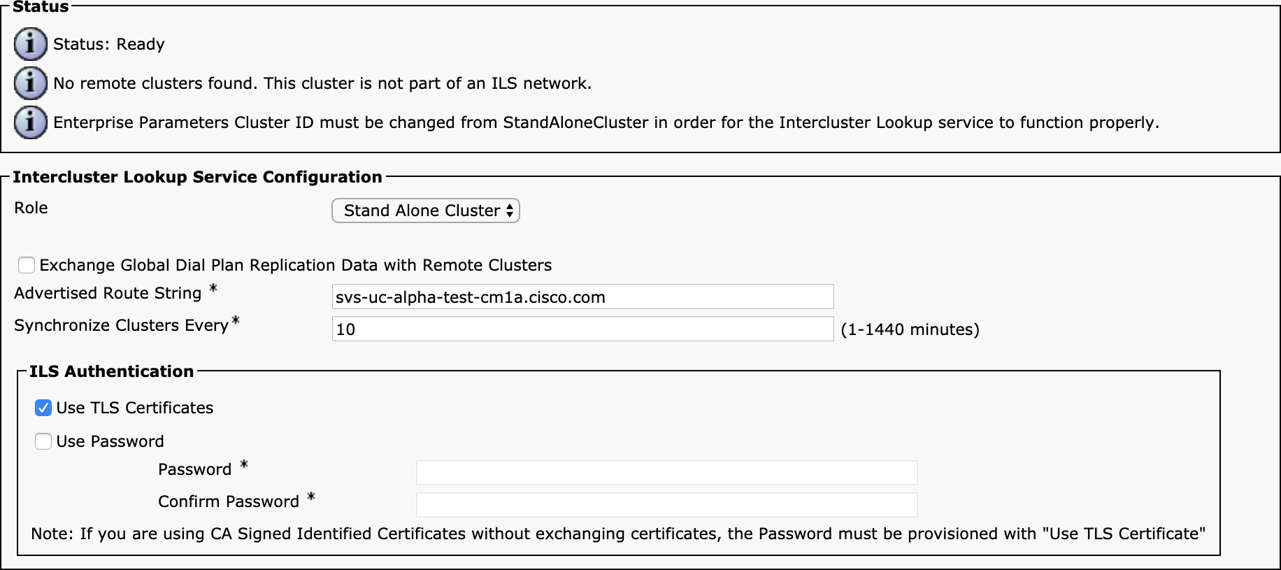
Figure 4-36 ILS Configuration
When configuring ILS, you first set the Role parameter for the cluster. The default setting is Stand Alone Cluster, which means the cluster is not part of an ILS network. You must select either Hub Cluster or Spoke Cluster. Also ensure that the Exchange Global Dial Plan Replication Data with Remote Clusters checkbox is selected. (We discuss Global Dial Plan Replication shortly.)
The next parameter is Advertised Route String. This string should be in DNS domain format, but it does not need to be a real DNS name because Unified CM will never perform a DNS query on this string. Unified CM will search for a SIP route pattern that matches this route string on other clusters that need to send calls to the cluster on which you are enabling ILS. For example, you can use the route string cluster1.example.com.
Next, you must configure the synchronization interval. By default Unified CM synchronizes every 10 minutes, but you can reduce this timer to as low as 1 minute or as long as 1 day.
Finally, you must select how you want clusters to authenticate each other. Clusters are not allowed to join the ILS network without proper authentication. You can use either certificate-based authentication or password-based authentication (or both). To use certificate-based authentication, you must exchange the Tomcat certificates between clusters. You can export the certificates from one cluster and import into the others by using the bulk certificate service or manually managing the certificates in Cisco Unified OS Administration. Hubs must trust certificates from all other hubs, and any spokes attached to a hub. Likewise, spokes must trust their hub. If you are using CA-signed certificates, you must exchange the certificates between clusters unless you also use a password. You can also choose to just use a password for authentication. This is a shared key, and it must be configured identically on all clusters in the ILS network.
When you save the ILS configuration page for the first time after changing the role, you see a popup dialog asking you to either enter the address of another hub in an existing ILS network or leave the entry blank if this is the first hub in the network. You also see the checkbox Activate the Intercluster Lookup Service on the Publisher in this Cluster, which is selected by default. Make sure you leave this checkbox selected and click OK. After a few minutes, ILS should be activated on the publisher, and the new network should be up or the cluster should join the existing network. You may have to click the Refresh button to update the list of clusters that appear at the bottom of the page. Repeat this process of creating more hubs and spokes and adding them to the network. When adding a hub, you can pick any existing hub to add it to the network. When adding a spoke, chose the hub carefully because this will be the hub to which the spoke replicates.
ILS can be used to advertise different information between clusters, but the focus of this chapter is on the ability to replicate dial plan information, including both URIs and numbers. By enabling the checkbox Exchange Global Dial Plan Replication Data with Remote Clusters when you enabled ILS, you have enabled the GDPR feature, but now you must understand how to make use of it.
Global Dial Plan Replication
The first purpose of the Global Dial Plan Replication (GDPR) feature is to facilitate the replication of directory URIs between clusters. If you have followed the steps described so far in this section, any URIs that you have configured on the clusters in the ILS network will be replicated as long as you left the Advertise Globally via ILS parameter enabled on the directory URI, as shown back in Figure 4-33. Remember that replicating across the whole ILS network can take up to three times the configured replication interval.
To check to see what URIs have been learned by a cluster, navigate to Unified CM Administration > Call Routing > Global Dial Plan Replication > Learned Directory URIs. You should see the learned URI, the cluster ID for the advertising cluster, and the route string associated with the URI. Figure 4-37 shows the sample output of the learned directory URIs page in Unified CM Administration.
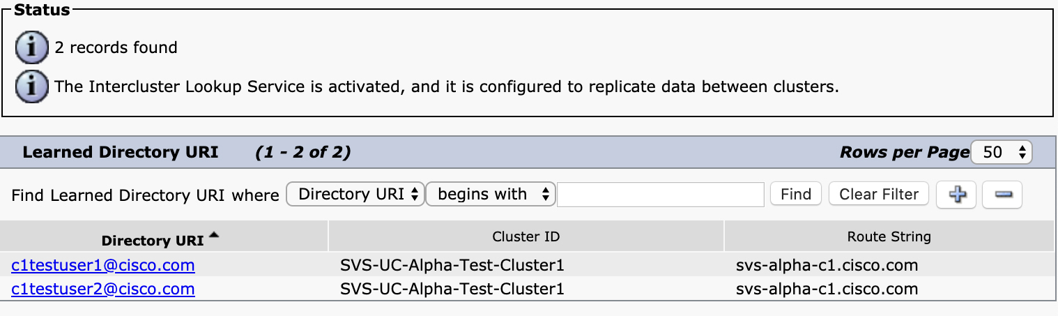
Figure 4-37 Learned Directory URIs
Now that the clusters have replicated the URIs via ILS, the remaining step is to configure routes so the clusters know how to reach each other, based on the advertised route strings. The first step is to create a SIP trunk that will be used to route the call to the destination cluster. (This configuration will be covered in Chapter 5.) The destination of the SIP trunk does not necessarily have to be the cluster that owns the route string. In larger enterprises, you might want to route all the calls from leaf clusters to a Session Management Edition (SME) cluster and then have the SME cluster route the calls to the advertising cluster. This is a perfectly valid—and in some cases recommended—design. For example, if you have 20 clusters named c1.example.com, c2.example.com, …, c20.example.com as well as an SME cluster, you can configure all the leaf clusters to send unknown calls destined to *.example.com to the SME cluster, and then the SME cluster can have individual routes to the specific route strings of the domains. This prevents you from having to configure 20 SIP trunks and 20 SIP route patterns on each leaf cluster. By aggregating the route string routing on the SME cluster, you reduce the configuration from 400 SIP trunks to 40 (1 on each of the 20 leaf clusters and then 20 on the SME). How you route the calls is completely independent of the advertisement of the route string.
To configure the routes between clusters, after you have created the SIP trunk to the destination, you create a route group that contains the SIP trunk and a route list containing the route group. Next, you create a SIP route pattern that matches either the exact route string being advertised by the destination cluster or a route string with a wildcard that will match. Ensure that this SIP route string is in a partition that is reachable from any devices you want to be able to dial a remote URI. A this point, you should have fully operational intercluster calling.
![]()
One important point to note is that while the route string is matched for the purposes of determining the destination to route a call, it is not used as the RHS of the URI when the call is routed. What does this mean? Say that a user dials [email protected]. The URI [email protected] is learned by Cluster 1 from Cluster 2 with a route string of c2.example.com. When Cluster 1 finds a match for [email protected], it sees that it is an ILS-learned URI, and the call needs to be routed using the route string c2.example.com. Cluster 1 performs a lookup for c2.example.com and finds a SIP route pattern that matches the route string and points to a route list/route group/SIP trunk. When the call is sent out the SIP trunk to Cluster 2, the request URI and to headers in the SIP INVITE both say the call is destined to [email protected]. Nowhere in the SIP message being sent to Cluster 2 does the route string c2.example.com appear. The route string is only used locally to make a local routing decision. It is optionally possible to send the route string as part of a special header in the outbound SIP INVITE message. To enable this functionality, you select the option Send ILS Learned Destination Route String on the SIP profile associated with the outbound SIP trunk. When you enable this parameter, you see that the outbound INVITE message includes a X-cisco-dest-route-string header with the route string value. For example, the call in Example 4-1 is being routed to the URI [email protected], and the route string included in the INVITE message is c2.example.com. Several headers have been removed or truncated in Example 4-1 in the interest of brevity.
Example 4-1 SIP Message with the X-cisco-dest-route-string Header
INVITE sip:[email protected] SIP/2.0
Via: SIP/2.0/TLS 10.122.249.71:5061;branch=z9hG4bK4f5b1d81b7c0
From: “Paul Giralt” <sip:[email protected]>;tag=151770~c1c9b4c0
To: <sip:[email protected]>
Date: Thu, 21 May 2020 16:43:29 GMT
Call-ID: [email protected]
Supported: 100rel,timer,resource-priority,replaces
Min-SE:  1800
CSeq: 101 INVITE
Session-Expires:  1800
X-cisco-dest-route-string: <sip:c2.example.com>
Contact: <sip:[email protected]:5061;transport=tls>;video;audio
Max-Forwards: 69
Content-Type: application/sdp
Content-Length: 5246
You can include the route string and use Cisco Unified Border Element (CUBE) to allow CUBE to route the call based on the route string instead of routing the call based on the URI. CUBE cannot participate in an ILS network, so this feature allows CUBE to be inserted in the signaling and media path between two clusters participating in an ILS network. ILS Call Routing with CUBE is discussed in Chapter 8.
Once you have enabled intercluster URI dialing, you can build on this and advertise directory numbers and other numeric patterns as well. Numeric patterns can generally be summarized, so the need to replicate them may not be as obvious as the need for URI replication. However, in large designs, being able to dynamically advertise directory numbers and patterns can serve two purposes. First, it makes provisioning easier. When you add a new number on a cluster, you can have it automatically advertised throughout the network to other clusters, and it becomes reachable without requiring changes to the configurations on the other clusters. In addition, this feature allows for automatic PSTN failover of calls that fail to be established via the on-net path by rerouting the calls over the PSTN destination.
GDPR for numeric patterns does not operate in the same way as URI replication. This is because numbers have different requirements. The fact that numbers can be summarized and that closest-match routing must be performed to find the correct match means that the simplistic rule of just checking to see if a numeric pattern has been learned or not does not work. GDPR allows you to advertise two distinct types of numeric routes: numbers and patterns. A number represents a specific directory number configured as a directory number on the line of a phone (along with some transformations performed on that number, which we discuss in a moment). Patterns are like route patterns in that they can contain wildcards and generally represent a range of numbers rather than one specific device. Numbers and patterns are further subdivided into two groups: enterprise numbers/patterns and +E.164 numbers/patterns.
![]()
Enterprise and +E.164 are really just placeholders for two different “buckets” you can advertise and place learned patterns into. There is nothing in the system that enforces that a number or pattern tagged as an +E.164 advertisement is actually in +E.164 format. That said, these two designations were created specifically to address real-world design challenges in which enterprises need the ability to replicate both +E.164 representations of a directory number along with an enterprise-specific number that might follow a global on-net private dial plan—for example, in a case where you might dial an access code followed by a site identifier followed by the extension of the phone at that site. Whatever you advertise via GDPR, you should ensure that it is global in nature.
To advertise a number into ILS via GDPR, navigate to the directory number on a device by either navigating to Unified CM Administration > Device > Phone > Directory Number on the Device or Unified CM Administration > Call Routing > Directory Number. On the directory number configuration page are two buttons for alternate numbers, labeled Add Enterprise Alternate Number and Add +E.164 Alternate Number. By default, a directory number does not have either one of these numbers. Figure 4-38 shows the administration page after both of the alternate number buttons are clicked.

Figure 4-38 Alternate Number Configuration on a Directory Number
Each of the alternate number configuration sections allows you to configure several parameters. The first is Number Mask. This parameter allows you to manipulate the directory number to convert it to a form that can be advertised to other clusters. In the example shown in Figure 4-38, the directory number configured on the line is the four-digit extension 1000. This is not a globally unique number. In fact, you may have many branches where the reception desk always has extension 1000, for example. You would like anyone to reach the reception desk at any site by dialing 8 followed by a 3-digit site code followed by the extension (1000 in this case). You would also like others to be able to reach this number by dialing its full +E.164 number. For the purposes of inbound call routing, you would have to somehow transform inbound calls to the +E.164 number into the directory number on this line, but instead of doing that, you can just create an alias for this extension with the full +E.164 number. The GDPR configuration allows you to do this in addition to advertising the pattern globally throughout your enterprise.
In this example, because this phone is located at site 555, the mask for the enterprise alternate number is 8555XXXX. As you type, the web page dynamically updates to show you the result of applying the mask to the directory number next to the Alternate Number field so you can be sure the number is as you expect it to be.
The next parameter, Add to Local Route Partition, allows you to make this transformed number available to dial for users on this same cluster. This essentially creates an alias for this directory number, using the alternate number, and places the alternate number into a partition of your choice. You must select which partition you would like to insert the pattern into by using the Route Partition field. When inserting into a local partition, you can select whether the pattern that is inserted is marked urgent priority or not.
The last parameter is the checkbox Advertise Globally via ILS. If this box is selected, the alternate number is advertised via ILS and associated with the route string for this cluster, along with a tag indicating the type of alternate numeric pattern—in this case, an alternate number.
The configuration is identical for the +E.164 alternate number configuration. In this case, the number mask applied translates the directory number to a full +E.164 pattern. By inserting this +E.164 pattern into a partition that is searched when callers place outbound PSTN calls, you enable a function often referred to as “forced on-net.” Basically, you are ensuring that if someone decides to place a call to one of your on-net extensions by dialing that number as if they were calling through the PSTN, the system recognizes this and routes the call directly between devices instead of sending the call out to the PSTN and back. This also allows you to preserve features such as video and wideband audio when users inadvertently dial each other using a PSTN dialing habit instead of using an on-net dial plan.
![]()
There is one additional configuration parameter related to GDPR on the line configuration page: the Advertised Failover Number selection. You can set this parameter to either Enterprise Number or +E.164 Number. This parameter tells the remote cluster which number should be used in the event of a failed call to this directory number. This failover number applies to calls made to any directory URIs configured on this directory number as well as any alternate numbers. This means you can now have PSTN failover for URI calls. For example, if a user dials [email protected] as an intercluster call that matches a URI learned via ILS and there is a failure for some reason, if an +E.164 alternate number is configured and advertised via ILS as well and marked as the advertised failover number, the call is rerouted over the PSTN. The calling device uses the AAR calling search space on the device to determine the path to the PSTN. You must ensure that the AAR calling search space has route patterns with routes to the PSTN that can match the failover number in +E.164 format for the failover to work.
This is all that is needed to advertise numbers between clusters, but additional configuration is required to be able to call these numbers from other clusters. The first piece of additional configuration you already did when configuring intercluster URI dialing: the configuration of SIP trunks and SIP route patterns to facilitate intercluster routing of calls via route string. There is one other bit of configuration needed that is unique to numeric GDPR advertisements. This configuration is found on the Unified CM Administration > Call Routing > Global Dial Plan Replication > Partitions for Learned Numbers and Patterns configuration page. Figure 4-39 shows this configuration page.
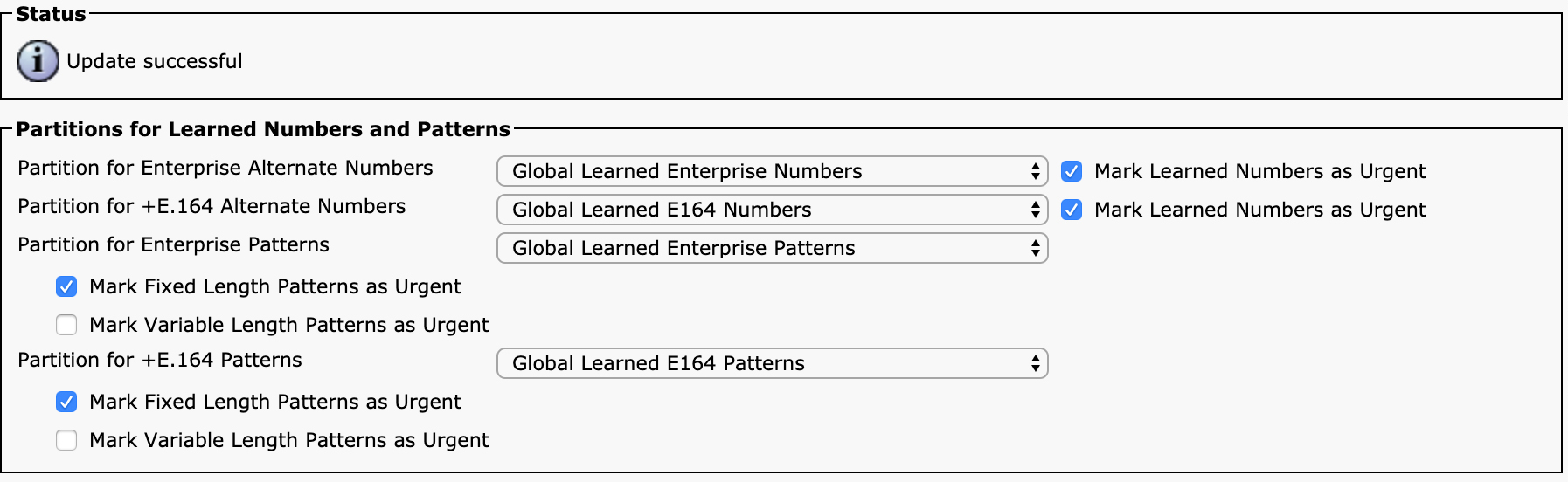
Figure 4-39 Alternate Number Configuration on a Directory Number
This configuration page determines what happens to advertised numbers and patterns that are learned by this cluster. Unlike URIs that are placed in a global ILS lookup table that is referenced when Unified CM cannot find a match for a local URI, numbers and patterns must be explicitly placed into a specific partition as they are learned. Four unique types of numbers and patterns can be advertised: enterprise alternate numbers, +E.164 alternate numbers, enterprise patterns, and +E.164 patterns. A number or pattern advertisement gets placed into the appropriate partition, based on its type. By default, the system comes preconfigured with four partitions for the different types of learned numeric advertisements, but you can choose to change the partition.
You have the option to mark the patterns that are learned as urgent or not. For learned patterns (which can contain wildcards), you also have the option to only mark patterns that are fixed length as urgent while keeping variable-length patterns non-urgent. You may be wondering why you might want to mark a pattern or number as urgent. Let’s consider a quick example.
Suppose you are following a methodology similar to the TEHO example discussed previously, where a user dialing a PSTN number matches a translation pattern, which then translates the number to +E.164 format. You may have just a simple route pattern of +! configured to send all calls to the PSTN after being translated to +E.164 format. If you wanted to intercept calls that should remain on-net, you could place the Global Learned E164 Numbers partition into the calling search space configured on the translation pattern so that after translating the number to +E.164 format, Unified CM not only searches for the partition containing the +! route pattern but also searches through the learned +E.164 patterns. If a better match is found in the learned patterns, the call is routed on-net. When you mark the learned patterns with urgent priority, the call gets routed immediately instead of waiting for additional digits.
Advertised patterns can be configured by navigating to Unified CM Administration > Call Routing > Global Dial Plan Replication > Advertised Patterns. Figure 4-40 shows a sample configuration for an advertised pattern.
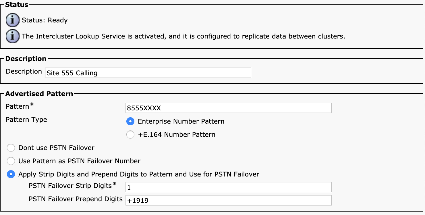
Figure 4-40 Advertised Pattern Configuration
The configuration of an advertised pattern is slightly different from the configuration of an alternate number. First of all, the pattern can contain wildcards, and the pattern can even be variable length. You can designate the pattern to be advertised as either an enterprise number pattern or an +E.164 number pattern. In addition, you have some options for PSTN failover advertisements. You can chose not to advertise any PSTN failover, advertise the number itself as the PSTN failover number (which is useful if the number being advertised is itself an +E.164 number, so the same number should be tried via the PSTN instead of via on-net), or manipulate the number by stripping a certain number of digits from the left side of the number and then prefixing a certain number of digits to create the failover pattern. You might wonder why you would take this approach instead of just adding a mask. Masks do not work for variable-length patterns because you don’t know how long you need to make the mask; masks don’t offer variable-length masking options.
The advertised patterns are placed into the appropriate partitions on the receiving clusters, and you can then incorporate the learned patterns into your dial plan in any way you see fit.
What if you are in a scenario where you have URIs that need to be routed to an external system that does not support ILS and GDPR, and those URIs are part of the same domain as the URIs that are being routed by the Unified CM clusters? Unified CM provides a mechanism to deal with this situation, through the use of an imported dial plan catalog. This is a mechanism by which you can import a CSV file containing a list of URIs or patterns and associate them with a route string, just as if those URIs had been learned from an external system advertising that route string.
Note that, by default, ILS and GDPR allow a cluster to insert up to 100,000 learned objects (URIs and alternate numbers) into the local database, but Unified CM can scale up to 1,000,000 entries on a properly sized cluster. To change the maximum number of learned objects, you must modify the ILS Max Number of Learned Objects in Database parameter for the Cisco Intercluster Lookup Service under Unified CM Administration > System > Service Parameters.
You now have all the tools you need to create a robust, scalable, global, multi-cluster dial plan for both numeric and alphanumeric URI dialing. Although you now have the tools and know the basics of how to use the tools, building a dial plan can sometimes be more of an art than a science. It can be tricky to take into account the requirements from end users as well as business and scaling requirements to build a dial plan that meets your business needs and that also provides the needed flexibility to your end users. You must practice building dial plans to become fully proficient in this art. Even after you have configured a dial plan, you are bound to run into challenges implementing it, so understanding how to troubleshoot dial plan–related issues is a key skill to master.
Troubleshooting Call Routing and Digit Manipulation
Unified CM provides a variety of built-in tools and logging that can help you diagnose and troubleshoot dial plan–related problems. In addition, external tools provided by Cisco and third parties can assist you in troubleshooting problems related to call routing and digit manipulation. Typically, call routing issues manifest as users attempting to place calls that do not complete. There are other variations, as well, such as inbound calls not ringing a phone or calls being routed to the wrong number or through the wrong gateway. Sometimes a call seems to complete, but the user ends up receiving a message indicating that there was a problem completing the call. This section explores the available tools to help you better diagnose the root causes of these types of issues.
This section discusses the following tools:
• Dialed Number Analyzer (DNA)
• Real-Time Monitoring Tool (RTMT)
• SDL trace files
• The trace parsing tools Collaboration Solutions Analyzer and TranslatorX
![]()
Dialed Number Analyzer
The Dialed Number Analyzer (DNA) tool is a built-in component of Unified CM that allows you to provide a set of dialed digits or URIs and ask Unified CM to return the digit analysis results and call flow information for how a given call would be routed through the system. It allows you to examine the call routing logic that would be used if such a call were to be placed on a real device. DNA has two modes of operation. In one mode, you can select a configured device—a phone, gateway, or trunk—and then ask the system what would happen if a call were to originate from that device with a given set of parameters. The other mode is a more generic analyzer that allows you to provide calling and called numbers along with a calling search space and ask the system to evaluate the call, based on those parameters. Both modes actually do the same thing. The only difference is that when you choose a device, DNA determines the calling number and calling search space information from the device (and line) instead of requiring you to enter it manually.
To access the DNA tool, you must first ensure that the service is activated and running. You do so from Cisco Unified Serviceability. If you are logged in to Unified CM Administration, navigate to Cisco Unified Serviceability > Tools > Service Activation. Activate both the Cisco Dialed Number Analyzer and Cisco Dialed Number Analyzer Server services. Both services must be activated for DNA to work.
Once you have the DNA services running, navigate to the DNA tool by navigating to Cisco Unified Serviceability > Tools > Dialed Number Analyzer or pointing your browser to https://<publisher_ip_address>/dna/.
The Analysis menu in DNA has the following options:
• Analyzer: Allows you to specify a calling number, calling search space, called number, and time and returns the results of the digit analysis match and call routing for that call.
• Gateways: Allows you to select a gateway and port on the gateway and then specify a calling number and a called number as well as a time for the call to analyze the call flow for that call.
• Phones: Allows you to select a line configured on a specific phone and analyze the call flow for a call placed from that line at a specific time to a specified dialed number.
• Trunks: Allows you to select a trunk and specify a calling number and a called number as well as a time for the call to analyze the call flow for that call.
• Dump DA Information: Dumps a full listing of the digit analysis tree, digit discard instructions, and learned patterns.
• Multiple Analyzer: Performs the same action as the Analyzer option, but allows you to import a CSV file with the data to analyze. DNA outputs a file with all the results.
• View File: Each of the results mentioned in this list can be saved to a file. This option allows you to open a previously saved analysis to view it in the browser.
The Analyzer, Gateways, Phones, Trunks, and Multiple Analyzer features all essentially do the same thing, so this section goes through a couple examples of calls that originate from a phone device. To analyze a call from a phone, navigate to Dialed Number Analyzer > Analysis > Phones and search for a phone. Figure 4-41 shows the Phones page, where you can select the line and specify the dialed digits or URI and the time.
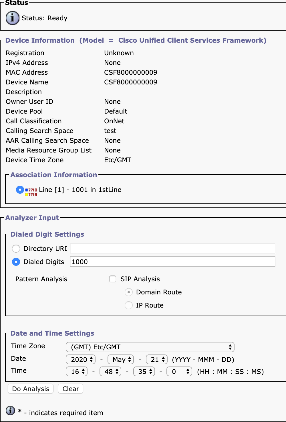
Figure 4-41 Dialed Number Analyzer Phone Analysis
You can see that the tool shows the phone configuration information and allows you to select a line—in this case line 1 with directory number 1001 in the 1stLine partition. In the Dialed Digits box, you see that 1000 has been entered. After entering this, you would click the Do Analysis button, which would cause a new window to appear with the analysis results, as shown in Figure 4-42.

Figure 4-42 Dialed Number Analyzer Phone Analysis Results
The first section of the results is the Results Summary section, which provides information on the final calling and called party numbers, including the pattern that matched. In this case, you can see that the dialed digits are 1000, but the matched pattern is 2000 in the test partition. You can also see that Match Result says either RouteThisPattern or BlockThisPattern to indicate whether the call should be routed or blocked. In this case, the results indicate that routing will be attempted. The Call Flow section gives you details on how that result was achieved.
In the Call Flow section, you can see that the dialed digits first match the translation pattern 1XXX in the test partition. You can see that there is a calling party transformation on the translation pattern that applies the mask +1919555XXXX to transform the calling party number to +19195551001. There is also a called party transformation that transforms the called party number to 2000.
The output of the translation pattern, 2000, then matches the directory number 2000 in the test partition. The Forwarding Information section is collapsed in Figure 4-42, but if you expand that section, you see all the forwarding options configured on the line. Next, you see the actual device that would ring if this call were placed. The device is a Jabber endpoint (Cisco Unified Client Services Framework) with the name CSF8000000007.
Notice the section at the bottom of the window labeled Alternate Matches. This section shows you other patterns that matched the dialed digits but with less-specific matches than the pattern that actually matched. In this example, you can see that there is an alternate match of XXXX, which is less specific than the 1XXX pattern that is shown to have matched.
As a second example, let’s examine what happens when you analyze a call that is destined to an external party through a SIP trunk. In this case, the phone is selected, and an analysis is done on the called party number 89915678. This example has some unusual transformations configured so you can see how they are displayed in DNA. This section looks at the results in two parts. First, Figure 4-43 shows the Results Summary section.

Figure 4-43 Dialed Number Analyzer Phone Analysis Results Summary
Notice that this section indicates that the calling party number is 80041000, the matched pattern is 8XXXXXXX, and the dialed digits are 89915678; however, the called party number shows 80029999. As you will see, this is somewhat misleading because the called party number can actually change depending on what trunk or gateway a call egresses. DNA is not making a real call, so it is just showing you all the possibilities of routing paths, and the called party number shown is the number after any transformations applied on the matching route pattern, but it does not include route list detail or gateway/trunk transformations. Those appear later, in the Call Flow section, the first part of which is shown in Figure 4-44.
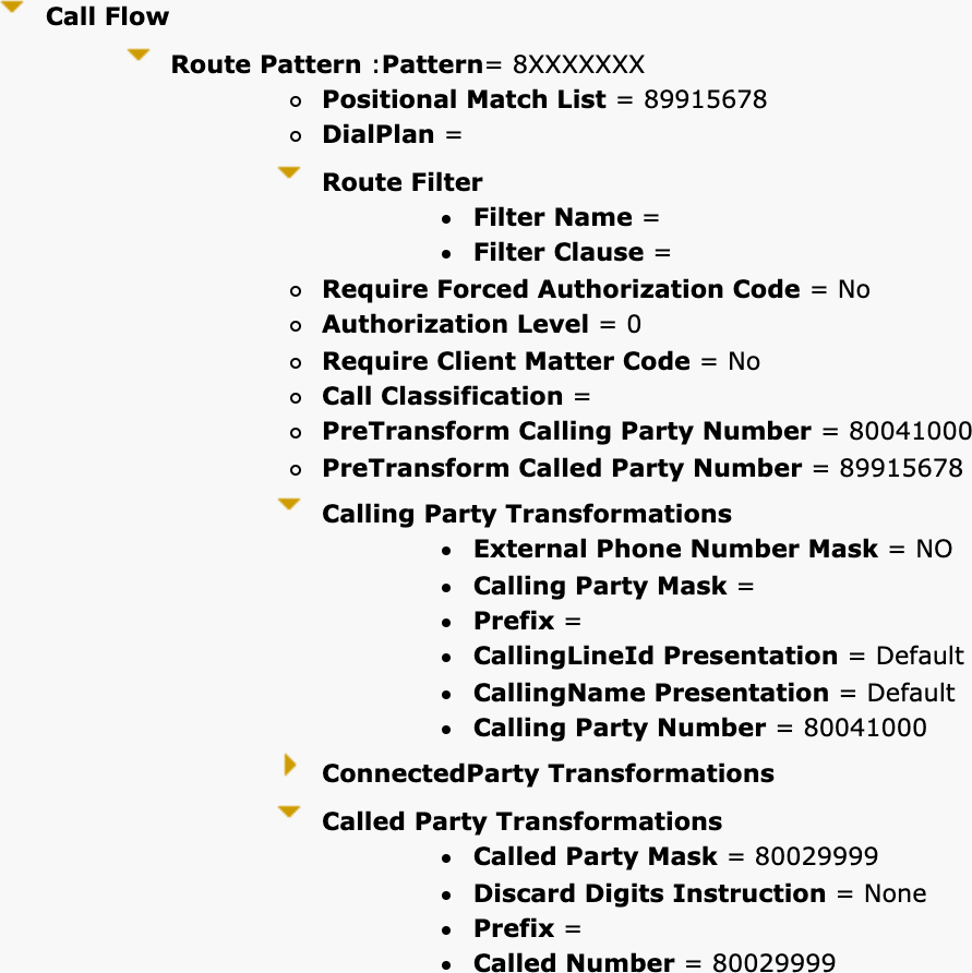
Figure 4-44 Dialed Number Analyzer Phone Analysis Results Call Flow
You can see that the pattern matched is 8XXXXXXX and that no calling party transformations are applied, but there is a called party transformation of 80029999. Figure 4-45 shows the remaining part of the Call Flow section, with the route list, route group, and SIP trunk details for the call.
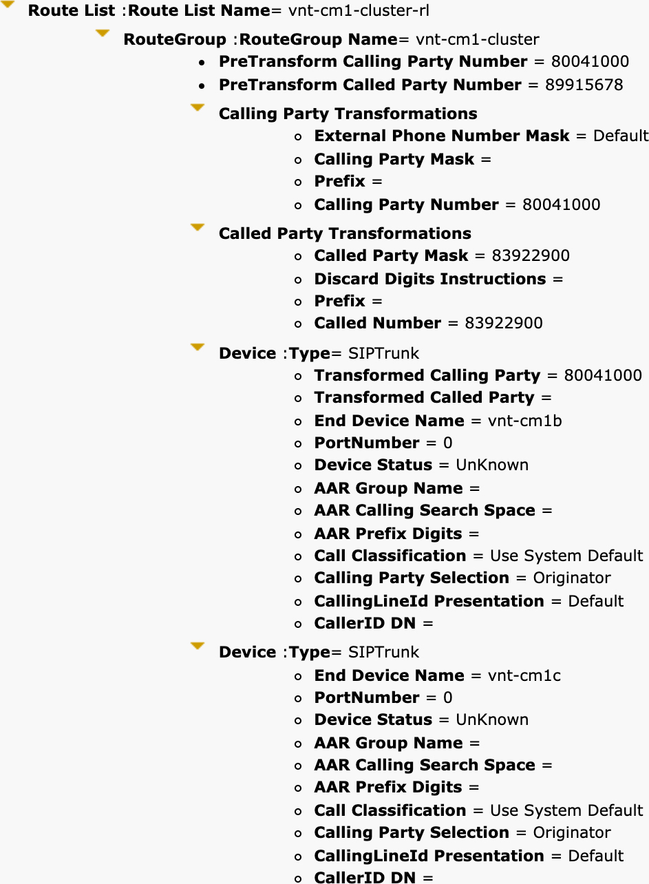
Figure 4-45 Dialed Number Analyzer Phone Analysis Results Route List
The route list matched is vnt-cm1-cluster-rl, which contains a single route group named vnt-cm1-cluster. The pre-transform calling and called party numbers are shown. Remember that any modifications performed on the route list are applied to the pre-transform numbers, so the called party number is back to being 8991578 for any modifications made on the route list details. You can see that in the route list details for this route group, there is a called party transformation that transforms the called party number to 83922900. The route group contains two SIP trunk named vnt-cm1b and vnt-cm1c. Since there are no transformations on the called party number on the SIP trunks, the number that would be sent out both trunks would be 83922900 in this case.
The analyzers for trunks, gateways, and the generic analysis/multiple analysis features operate the same way as the phone feature in DNA, so there is no need to go into detail on how those features work. For any of these features, you can click the Save button in the top-right corner of the analysis results window to save the results in an XML file. You can then use the Analyzer > View File menu to open those results at a later time.
DNA gives you the power to view hypothetical calls traversing through a Unified CM cluster, but what if you want to look at real calls? In such cases, you must use either the Session Trace feature for SIP calls or look at the SDL trace files generated by Unified CM. To do either of these, you need to use the Real-Time Monitoring Tool (RTMT).
Real-Time Monitoring Tool
The Real-Time Monitoring Tool (RTMT) is an application you install on a client PC and connect to a Unified CM cluster to perform real-time diagnostics on the cluster. We do not go into great detail about all the capabilities of RTMT, but this section discusses a few features that are useful for troubleshooting issues related to call routing. If you have not already installed RTMT on your PC, navigate to Unified CM Administration > Application > Plugins and download and install RTMT for Windows or Linux.
Once installed, launch the application and log in. You should see a window similar to the one in Figure 4-46.
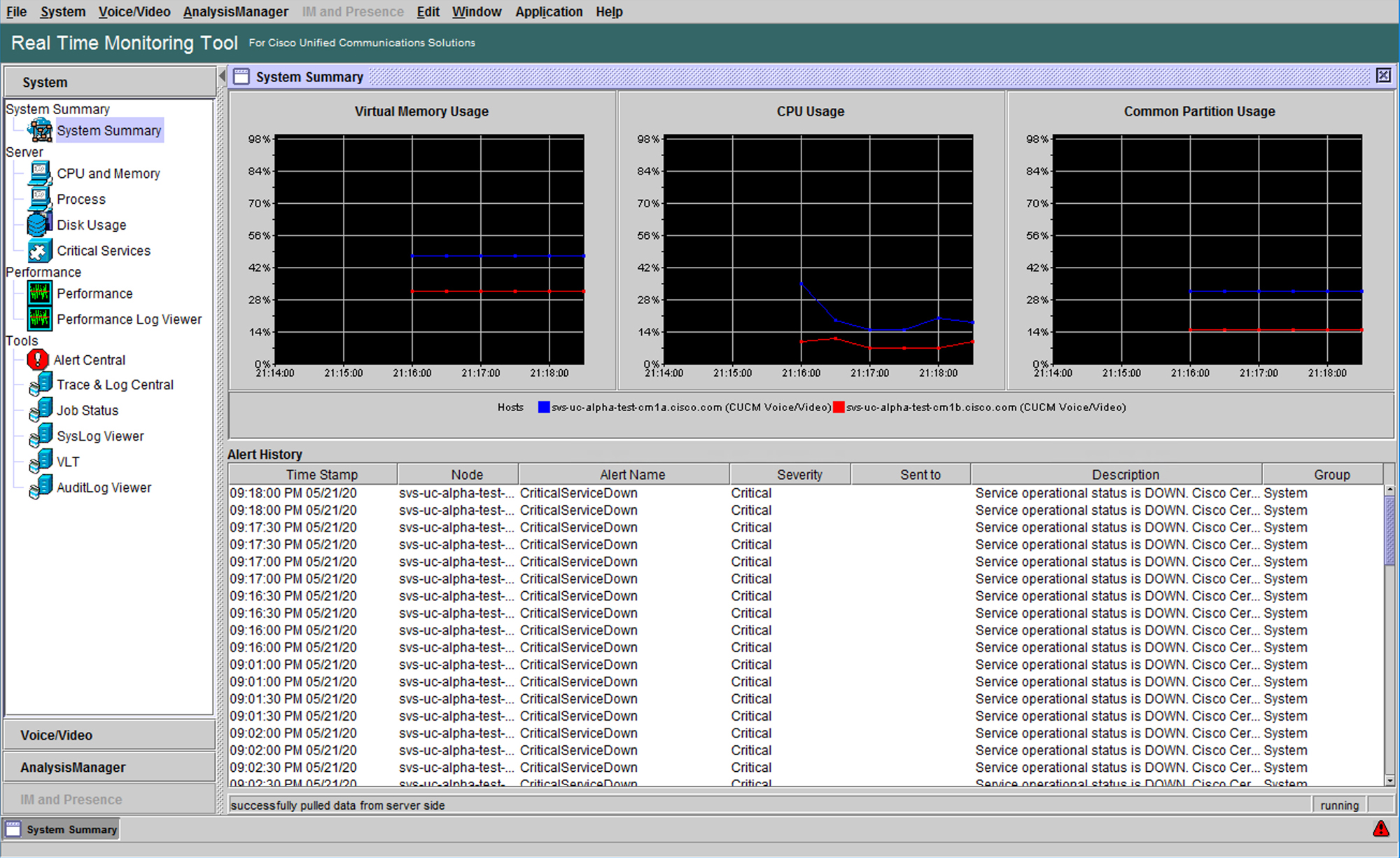
Figure 4-46 Real-Time Monitoring Tool
![]()
The first feature of RTMT that is useful for diagnosing call routing issues is the Session Trace Log View feature. You can find this tool by navigating to RTMT > Voice/Video > Session Trace Log View > Real Time Data. You then see a list of the last 30 minutes of calls, by default. Figure 4-47 shows an example of the session trace call list that appears.
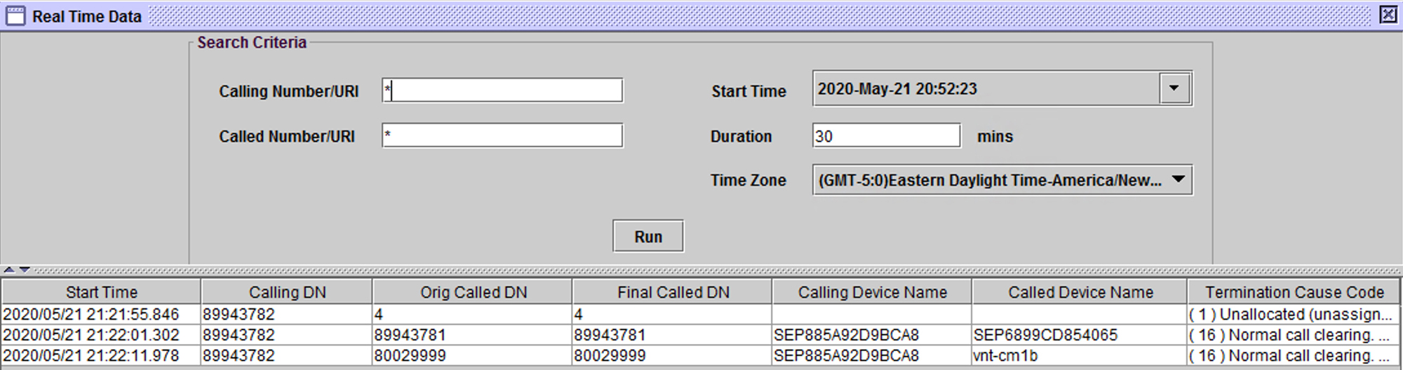
Figure 4-47 Session Trace Search and Call List
You can see three calls in the list shown in Figure 4-47. If you want to search for a different timeframe, you can change the start time and duration. You can only search for up to 60 minutes at a time. You can also specify the calling or called number to search for. The asterisk character is a wildcard. By default, the search is for any calling or called party number.
This call view provides you with some useful information. It shows you the calling and called party numbers. Note that what is listed under Final Called DN is actually not necessarily what gets sent out to the destination. Remember from the DNA example how the called number shown was the number after the transformations on the route pattern; if there are any transformations done on the route list details or transformation patterns on the trunk, they do not appear in this view of the call. You can also see the calling and called devices, so without looking any further, you already know which trunk or gateway (or phone, in the case of an on-net call) the call was destined to. Finally, this view gives you a termination cause code, which indicates the reason the call ended. This cause code can be a “normal” cause code such as cause code 16, which is a normal call clearing. It can also be an abnormal (or perhaps expected) cause code, such as 1, which is an unallocated (unassigned) number.
In the first call in the list in the example in Figure 4-47, you can see that the called number is just the digit 4. This call fails immediately because there are no patterns on this Unified CM cluster that start with a 4. The next two calls connect successfully. You can double-click on any of the calls listed here to pull up a ladder diagram of the calls for a quick visualization of the SIP signaling involved in the call. To get more details on the SIP signaling, you can use one of the post-processing tools discussed later in this chapter.
A useful feature in RTMT for diagnosing call routing–related issues is the Trace & Log Central tool, which enables you to download the trace files for the timeframe of an issue you have experienced and then use a post-processing tool to analyze the files. To use Trace & Log Central, navigate to RTMT > System > Tools > Trace & Log Central > Collect Files. You are presented with a window that lists all the services and servers from your Unified CM cluster, as shown in Figure 4-48.
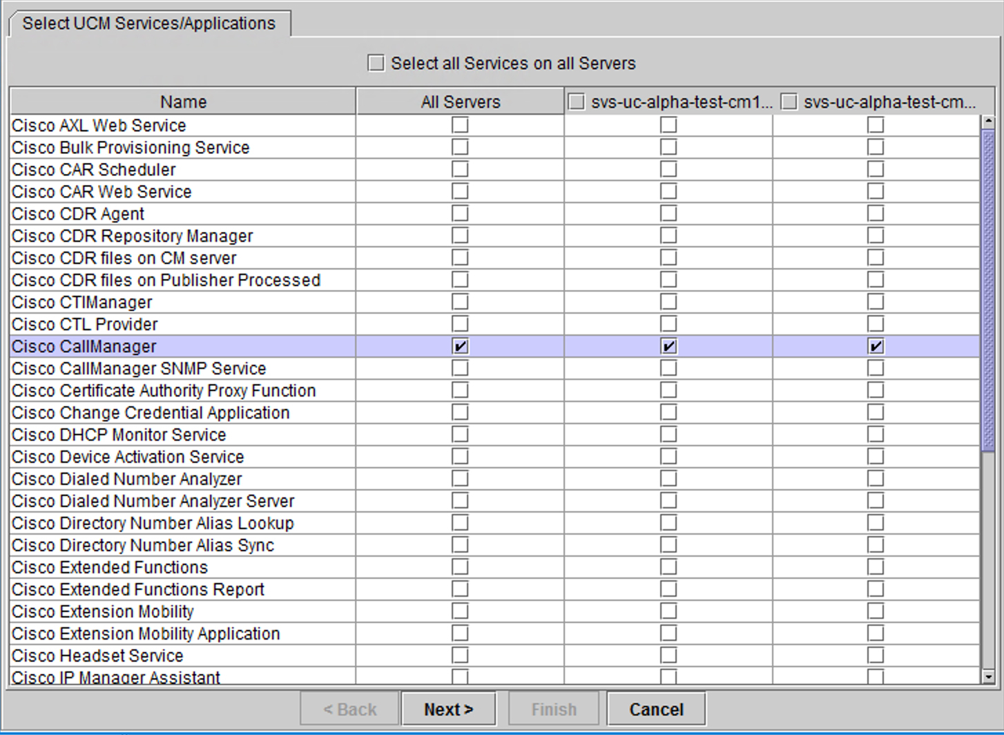
Figure 4-48 Trace & Log Central in RTMT
![]()
To gather call routing–related log messages, the only service you need to collect data from is the Cisco CallManager service. Check the box in the column labeled All Servers to download files from all the servers in the cluster. Click Next twice until you get to the Collect File Options page. This is where you can specify the timeframe for the traces you want to collect. If you are troubleshooting a problem that is easily reproducible, just reproduce the problem and then use the Relative Range option to select traces from the last 5 or 10 minutes. If you are trying to diagnose an issue that happened in the past, select the appropriate timeframe in the Absolute Range section. Select a directory in which to place the downloaded files and then click Finish. After a few minutes, you should have the files from all the servers in the cluster downloaded for the timeframe in question. Once you have downloaded the files, you can explore them manually or use a post-processing tool to analyze them.
Troubleshooting Call Routing by Using SDL Trace Files
When you have downloaded the SDL trace files from Unified CM, you will have a hierarchy of folders in the folder you designated as the download location. You will have a folder for each server in the cluster, and in each of those folders you will have a folder with the timestamp of the trace collection. Below that you can see the folders cm > trace > ccm > sdl, where you can find all the SDL trace files in gzip (.gz) format. You can generally leave the files in .gz format because most text reading tools can natively read .gz files. To troubleshoot call routing issues in the raw SDL trace files, open a file in your favorite text editor. You need to know which server folder to look at first. You want to look at the folder for the server to which the originating or calling device is registered. If the call arrives via a trunk, it may be hard to determine which server the call originated from. (You will see shortly that the post-processing tools make this task much easier.)
When you first open the SDL trace file, it can be a bit overwhelming. This section shows you the places to look, and then when you learn to use the post-processing tools, you will see how you can automate this process. The first thing to understand in these trace files is how dial plan–related information appears in the traces. Recall that digit analysis is the process that handles all number and URI lookups in Unified CM. Any time digit analysis is called to perform a match, you see a line that looks like Example 4-2 in the SDL trace file.
![]()
Let’s break down each section of the trace line shown in Example 4-2. First of all, to find lines like this, you just need to search for the text “Digit analysis: match,” and you will see a line very similar to this any time you search for that text. The fqcn value is the calling number with the external phone number mask applied. It does not necessarily mean that the external phone number mask will actually be used for this call; it just means that this is the masked number in case it is needed. The cn value indicates the calling party number. The pss field is a representation of the calling search space, but it is shown as the list of the partitions that will be searched. If this is a call from a phone, you see the list of partitions from the line calling search space followed by the partitions from the device calling search space, with any duplicates removed. The TodFilteredPss field is the list of partitions again, but it does not include partitions that are inactive because the configured time schedule indicates that it should not be active. The dd value stands for dialed digits and indicates the number that is being analyzed using digit analysis.
Example 4-2 Unified CM Digit Analysis Trace Snippet
02102283.008 |21:21:54.310 |AppInfo |Digit analysis: match(pi="2",fqcn="+19199943782", cn="89943782", plv="5", pss="Directory URI:Global Learned E164 Numbers:Global Learned E164 Patterns:Global Learned Enterprise Numbers:Global Learned Enterprise Patterns:Internal:International:Local:LongDistance:PhoneLines", TodFilteredPss="Directory URI:Global Learned E164 Numbers:Global Learned E164 Patterns:Global Learned Enterprise Numbers:Global Learned Enterprise Patterns:Internal:International:Local:LongDistance:PhoneLines", dd="4",dac="1")
Any digit analysis request results in a digit analysis response. In this case, you see the following two lines appear in the trace, as shown in Example 4-3. The first line indicates a message from digit analysis saying that no potential matches exist. This in and of itself does not necessarily indicate a problem. When Unified CM says that no potential matches exist, it means that there are no patterns that have partially matched, but if the user were to continue dialing more digits, there might be a match. When Unified CM decides that there are no potential matches (in other words, there is nothing the user could possibly dial beyond what has already been dialed to match a different pattern that requires more digits than have already been dialed), Unified CM makes an immediate decision on the disposition of the call. Either the call is routed because there is a match (and no potential matches) or the call fails because there is no match and there are no potential matches, so there is no point in allowing the user to dial additional digits.
![]()
In this case, you do not see a match. You only see the message indicating that no potential matches exist. If there is no match and there are no potential matches, Unified CM is indicating that there is no number that matches what has been dialed so far, and there is no point in continuing to wait for more digits because there is no pattern that could potentially match, given what has been received so far.
By using these digit analysis lines, you can very quickly see what numbers have been dialed by a user as well as the configured calling search space that is being used to look up a match. In Example 4-3, if you expect the user to be able to dial a number that begins with a 4, you would want to look at the pattern that you think should be matching and make sure it appears in one of the partitions listed. If it does not, you have to move the pattern to the correct partition or modify the calling party device’s calling search space to include the required partition.
Example 4-3 Digit Analysis and NoPotentialMatchesExist Explained
02102283.009 |21:21:54.310 |AppInfo  |Digit analysis: potentialMatches=NoPotentialMatchesExist
02102284.000 |21:21:54.310 |SdlSig   |DaRes                                  |setup_da                       |Cdcc(2,100,39,35)                |Da(2,100,47,1)                   |2,100,251,51.1319^10.122.251.105^SEP885A92D9BCA8 |[R:N-H:0,N:0,L:0,V:0,Z:0,D:0] CI=49629837 Block NoPotentialMatchesExist OnNetpatternUsage =2requestID =0
For a second call, you might see something that looks like Example 4-4 in the trace file. This time, you can see that the user dialed the digit 8, as evidenced by dd="8". Notice that this time, the message from digit analysis indicates that potential matches exist. When potential matches exist, Unified CM continues to wait for more digits.
Example 4-4 Unified CM Digit Analysis Showing PotentialMatchesExist
02102559.008 |21:21:58.612 |AppInfo  |Digit analysis: match(pi="2",fqcn="+19199943782", cn="89943782", plv="5", pss="Directory URI:Global Learned E164 Numbers:Global Learned E164 Patterns:Global Learned Enterprise Numbers:Global Learned Enterprise Patterns:Internal:International:Local:LongDistance:PhoneLines", TodFilteredPss="Directory URI:Global Learned E164 Numbers:Global Learned E164 Patterns:Global Learned Enterprise Numbers:Global Learned Enterprise Patterns:Internal:International:Local:LongDistance:PhoneLines", dd="8",dac="1")
02102559.009 |21:21:58.612 |AppInfo  |Digit analysis: potentialMatches=PotentialMatchesExist
Up until now, we have not really explored how Unified CM has been receiving these digits for processing. If you want to dig a bit deeper, you need to look at the protocol-level signaling. In most cases today, that signaling is SIP. Shortly before the digit analysis match for the digit 8, you see a SIP INVITE with only the digit 8 in the Request-URI. This INVITE is shown in Example 4-5. You can see that this is an inbound INVITE from an IP phone, and the phone is indicating to Unified CM that it would like to place a call to the digit 8—hence the subsequent lookup to digit analysis for this digit.
Example 4-5 Initial INVITE from IP Phone to Unified CM with the First Digit Dialed by the User
INVITE sip:[email protected];user=phone SIP/2.0
Via: SIP/2.0/TCP 10.122.251.105:49369;branch=z9hG4bK2e7256b7
From: “Test Phone 2” <sip:[email protected]>;tag=885a92d9bca81de3071848f1-47f71bef
To: <sip:[email protected]>
Call-ID: [email protected]
Max-Forwards: 70
Session-ID: 47dbbea900105000a000885a92d9bca8;remote=00000000000000000000000000000000
Date: Fri, 22 May 2020 01:21:49 GMT
CSeq: 101 INVITE
User-Agent: Cisco-CP7841/12.6.1
Contact: <sip:[email protected]:49369;transport=tcp>;+u.sip!devicename.ccm.cisco.com="SEP885A92D9BCA8"
Expires: 180
Accept: application/sdp
Allow: ACK,BYE,CANCEL,INVITE,NOTIFY,OPTIONS,REFER,REGISTER,UPDATE,SUBSCRIBE,INFO
Remote-Party-ID: “Test Phone 2” <sip:[email protected]>;party=calling;id-type=subscriber;privacy=off;screen=yes
Supported: replaces,join,sdp-anat,norefersub,resource-priority,extended-refer,X-cisco-callinfo,X-cisco-serviceuri,X-cisco-escapecodes,X-cisco-service-control,X-cisco-srtp-fallback,X-cisco-monrec,X-cisco-config,X-cisco-sis-7.0.0,X-cisco-xsi-8.5.1
Allow-Events: kpml,dialog
Recv-Info: conference
Recv-Info: x-cisco-conference
Content-Length: 689
Content-Type: application/sdp
Content-Disposition: session;handling=optional
Because potential matches exist, Unified CM needs to be able to accept additional digits from the phone. In order to accomplish this, Unified CM sends a SUBSCRIBE message to the phone to subscribe to KPML. The full process of completing a subscription for SIP KPML is detailed in Chapter 3, “VoIP Protocols: RTP, RTCP, and DTMF Relay.” As a result, this chapter skips that topic and jumps directly to the SIP NOTIFY message sent by the IP phone in Example 4-6. The IP phone sends a NOTIFY with an XML message body containing the rest of the digits dialed as the user presses keys on the keypad. Example 5-6 details the next digit, 9, being sent from the IP phone to Unified CM.
Example 4-6 SIP NOTIFY Message with the KPML Digit 9
NOTIFY sip:[email protected]:5060;transport=tcp SIP/2.0
Via: SIP/2.0/TCP 10.122.251.105:49369;branch=z9hG4bK1c17832c
To: <sip:[email protected]>;tag=1670742895
From: <sip:[email protected]>;tag=885a92d9bca81de51405294e-6f84d4a8
Call-ID: [email protected]
Session-ID: b8ce549500105000a000885a92d9bca8;remote=00000000000000000000000000000000
Date: Fri, 22 May 2020 01:21:50 GMT
CSeq: 1001 NOTIFY
Event: kpml
Subscription-State: active; expires=7200
Max-Forwards: 70
Contact: <sip:[email protected]:49369;transport=tcp>;+u.sip!devicename.ccm.cisco.com="SEP885A92D9BCA8"
Allow: ACK,BYE,CANCEL,INVITE,NOTIFY,OPTIONS,REFER,REGISTER,UPDATE,SUBSCRIBE
Content-Length: 205
Content-Type: application/kpml-response+xml
Content-Disposition: session;handling=required

<?xml version="1.0” encoding="UTF-8"?>
<kpml-response xmlns="urn:ietf:params:xml:ns:kpml-response” version="1.0” code="200” text="OK” suppressed="false” forced_flush="false” digits="9" tag="Backspace OK"/>
After Unified CM accepts the SIP NOTIFY and sends a 200 OK response, you see a new digit analysis performed on the new number. Example 4-7 shows the digit analysis for the second digit received by Unified CM. You can see that the dialed digits have now accumulated to 89, and there are still potential matches.
Example 4-7 Digit Analysis for the Second Digit Dialed by the IP Phone User
02102591.008 |21:21:59.385 |AppInfo  |Digit analysis: match(pi="2",fqcn="+19199943782", cn="89943782", plv="5", pss="Directory URI:Global Learned E164 Numbers:Global Learned E164 Patterns:Global Learned Enterprise Numbers:Global Learned Enterprise Patterns:Internal:International:Local:LongDistance:PhoneLines:Block_Check", TodFilteredPss="Directory URI:Global Learned E164 Numbers:Global Learned E164 Patterns:Global Learned Enterprise Numbers:Global Learned Enterprise Patterns:Internal:International:Local:LongDistance:PhoneLines:Block_Check", dd="89",dac="1")
02102591.009 |21:21:59.385 |AppInfo  |Digit analysis: potentialMatches=PotentialMatchesExist
This process of digit-by-digit analysis continues until the point where the phone dials something that matches. Skipping forward a bit, Example 4-8 shows the action that occurs when the user has dialed the digits 89915678. Any time there is a match, you see the line “Digit analysis: analysis results.” You can search for this key phrase to look for all instances of pattern matching in a trace file.
Example 4-8 Digit Analysis Showing Analysis Results for 89915678
02103238.011 |21:22:11.970 |AppInfo  |Digit analysis: match(pi="2", fqcn="+19199943782", cn="89943782",plv="5", pss="Directory URI:Global Learned E164 Numbers:Global Learned E164 Patterns:Global Learned Enterprise Numbers:Global Learned Enterprise Patterns:Internal:International:Local:LongDistance:PhoneLines:Block_Check", TodFilteredPss="Directory URI:Global Learned E164 Numbers:Global Learned E164 Patterns:Global Learned Enterprise Numbers:Global Learned Enterprise Patterns:Internal:International:Local:LongDistance:PhoneLines:Block_Check", dd="89915678",dac="1")
02103238.012 |21:22:11.970 |AppInfo  |Digit analysis: analysis results
Any time there is a match, as shown in Example 4-8, the output shown in Example 4-9 follows. This is the full digit analysis result, which contain lots of useful information.
![]()
Example 4-9 Full Digit Analysis Results for the Dialed Number
02103238.012 |21:22:11.970 |AppInfo  |Digit analysis: analysis results
02103238.013 |21:22:11.970 |AppInfo  ||PretransformCallingPartyNumber=89943782
|CallingPartyNumber=89943782
|DialingPartition=Internal
|DialingPattern=8XXXXXXX
|FullyQualifiedCalledPartyNumber=89915678
|DialingPatternRegularExpression=(8[0-9][0-9][0-9][0-9][0-9][0-9][0-9])
|DialingWhere=
|PatternType=Enterprise
|PotentialMatches=NoPotentialMatchesExist
|DialingSdlProcessId=(0,0,0)
|PretransformDigitString=89915678
|PretransformTagsList=SUBSCRIBER
|PretransformPositionalMatchList=89915678
|CollectedDigits=80029999
|UnconsumedDigits=
|TagsList=SUBSCRIBER
|PositionalMatchList=89915678
|VoiceMailbox=
|VoiceMailCallingSearchSpace=
|VoiceMailPilotNumber=
|RouteBlockFlag=RouteThisPattern
|RouteBlockCause=0
|AlertingName=
|UnicodeDisplayName=
|DisplayNameLocale=1
|OverlapSendingFlagEnabled=0
|WithTags=
|WithValues=
|CallingPartyNumberPi=NotSelected
|ConnectedPartyNumberPi=NotSelected
|CallingPartyNamePi=NotSelected
|ConnectedPartyNamePi=NotSelected
|CallManagerDeviceType=NoDeviceType
|PatternPrecedenceLevel=Routine
|CallableEndPointName=[a2b59152-1bfe-d81e-2b27-379fe16e2727]
|PatternNodeId=[71a1456e-9a38-6460-a76d-857e4361f89b]
|AARNeighborhood=[]
|AARDestinationMask=[]
|AARKeepCallHistory=true
|AARVoiceMailEnabled=false
|NetworkLocation=OnNet
|Calling Party Number Type=Cisco Unified CallManager
|Calling Party Numbering Plan=Cisco Unified CallManager
|Called Party Number Type=Cisco Unified CallManager
|Called Party Numbering Plan=Cisco Unified CallManager
|ProvideOutsideDialtone=false
|AllowDeviceOverride=false
|IsEmergencyNumber=false
|AlternateMatches=
|TranslationPatternDetails=
|ResourcePriorityNamespace=
|PatternRouteClass=RouteClassDefault
You can see in Example 4-9 that there is a lot of information to process. This output gives you information about the final route pattern or directory number that matched the dialed digits. If this is a route pattern match, the results indicate any transformations that were applied on the route pattern. The one thing you do not see here by default is any translation patterns that were involved in routing this call. Numbers are just magically translated without any indication as to how this occurred. Recall that the DNA tool shows translation pattern results.
![]()
Although the default behavior is to not show translation pattern or alternate pattern results in the trace, you can (and should) configured Unified CM to do so. This capability is controlled by the service parameter Digit Analysis Complexity. You can find this parameter by navigating to Unified CM Administration > System > Service Parameter, selecting a server in the cluster, and selecting the Cisco CallManager service. You can then find the Digit Analysis Complexity parameter in the System section and change the value of the parameter to TranslationAndAlternatePatternAnalysis. Note that this parameter is not a clusterwide parameter, which means you must select each server in the cluster independently to enable the parameter on each one. While you are here changing parameters, take a moment to make sure the CDR Enabled Flag parameter is set to True. Even if you are not using call detail records for billing purposes, they can be useful for troubleshooting, as you will see later. Note that this parameter also must be configured on each node individually and does not apply clusterwide.
Another parameter worth enabling is the CDR Log Calls with Zero Duration flag, which shows call detail records for calls that may not generate a CDR—namely, calls that do not connect (and therefore have a zero duration) but for which the cause code for the call failure is considered to be normal. This can happen when a call is routed to the PSTN and the PSTN plays a recording indicating that the call failed, resulting in the caller hanging up the phone. From Unified CM’s perspective, the call ended “normally,” with the user hanging up before the remote participant answered the call.
Once a digit analysis match has been performed, Unified CM attempts to route the call to the device associated with this pattern. The CallableEndPointName entry in the analysis results indicates the endpoint where the call will be routed. The value is provided as a database primary key identifier (PKID), so it is not immediately obvious what the called device is. It appears later in the trace, however, so if you want to look up the value in the database, you can query the device table with the platform CLI command on the publisher, as shown in Example 4-10.
Example 4-10 Unified CM SQL Query for Device PKID Based on CallableEndPointName
admin: run sql select name from device where pkid='a2b59152-1bfe-d81e-2b27-379fe16e2727'
name
==================
vnt-cm1-cluster-rl
Continuing through the traces, you can see that the endpoint associated with this pattern is a route list, so Unified CM proceeds to find a match in the route list. The first line in the trace indicates that routing to the route list has started. Here you can see the name of the route list and the fact that it has two members. A few lines later, you see more details on this count. Here you can see that there is a single route group with two devices in it, as shown in Example 4-11. You also see a line indicating the distribution algorithm configured. The type field indicates the distribution algorithm, with 1 being Top Down and 2 being Circular.
Example 4-11 Unified CM Traces Showing Route List and Route Group Information
02103253.001 |21:22:11.971 |AppInfo  |RouteListControl::idle_CcSetupReq - RouteList(vnt-cm1-cluster-rl), numberSetup=0 numberMember=2 vmEnabled=0

02103254.007 |21:22:11.972 |AppInfo  |RouteList - RouteGroup count=''1''
02103254.008 |21:22:11.972 |AppInfo  |RouteListCdrc - RouteGroup count = 1
02103254.009 |21:22:11.972 |AppInfo  |RouteListCdrc - Device count = 2

02103258.003 |21:22:11.972 |AppInfo  |RouteListCdrc::algorithmCategorization -- CDRC_SERIAL_DISTRIBUTION type=1
Next, you can see all the route list transformations being applied for this route group. Example 4-12 details the called party number being transformed to 83922900. Recall that the digit analysis results as well as the RTMT call list indicated that the called party number was 80029999, but here you can see that the route list is overriding that.
Example 4-12 Digit Manipulation on the Route Group
02103258.006 |21:22:11.972 |AppInfo  |RouteListCdrc::createPartyTransformedCcSetupReqMsg - before DAapplyCdpnXform() preXformCdpn=89915678 preTag=SUBSCRIBER prePos=89915678 crCdpnMask=83922900 crPrefixDigit= crDDI=0
02103258.007 |21:22:11.972 |AppInfo  |RouteListCdrc::createPartyTransformedCcSetupReqMsg - after  DAapplyCdpnXform() xformCdpn=83922900 xformTag=SUBSCRIBER xformPos=89915678
02103258.008 |21:22:11.972 |AppInfo  |RouteListCdrc::transformed cdpn (without unconsumpt digits) = 83922900, unconsumed digit=
Finally, as shown in Example 4-13, you can see that the route list finally routes the call to the first route group member.
Example 4-13 Unified CM Selecting a Device in the Route Group
02103259.003 |21:22:11.972 |AppInfo |SMDMSharedData::findLocalDevice - Name=vnt-cm1b Key=cb9c24be-3d11-2003-cca8-ae393967ef64 isActvie=1 Pid=(2,181,13) found
Finally, an outbound SIP INVITE is sent to the destination of the SIP trunk, as shown in Example 4-14. Notice that the request URI in the SIP INVITE is [email protected], which is the transformed number from the route list details.
Example 4-14 Outbound SIP INVITE Sent to the Destination Selected on the SIP Trunk
02103289.001 |21:22:11.977 |AppInfo  |SIPTcp - wait_SdlSPISignal: Outgoing SIP TCP message to 172.18.106.59 on port 5061 index 68
[333047,NET]
INVITE sip:[email protected]:5061 SIP/2.0
Via: SIP/2.0/TLS 10.122.249.71:5061;branch=z9hG4bK53603d10240
From: “Test Phone 2” <sip:[email protected]>;tag=159601~c1c9b4c0-de76-4127-bdc8-97f098ac0580-49629843
To: <sip:[email protected]>
Date: Fri, 22 May 2020 01:22:11 GMT
Call-ID: [email protected]
Supported: 100rel,timer,resource-priority,replaces
Min-SE:  1800
User-Agent: Cisco-CUCM12.5
Allow: INVITE, OPTIONS, INFO, BYE, CANCEL, ACK, PRACK, UPDATE, REFER, SUBSCRIBE, NOTIFY
CSeq: 101 INVITE
Expires: 180
Allow-Events: presence, kpml
Supported: X-cisco-srtp-fallback,X-cisco-original-called
Call-Info: <urn:x-cisco-remotecc:callinfo>; security= Unknown; gci= 2-1037; isVoip, <sip:10.122.249.71:5061>;method="NOTIFY;Event=telephone-event;Duration=500"
Call-Info: <urn:x-cisco-remotecc:callinfo>;x-cisco-video-traffic-class=DESKTOP
Session-ID: 3a72348700105000a000885a92d9bca8;remote=00000000000000000000000000000000
Cisco-Guid: 2815633664-0000065536-0000000026-1207532042
Session-Expires:  1800
P-Asserted-Identity: “Test Phone 2” <sip:[email protected]>
Remote-Party-ID: “Test Phone 2” <sip:[email protected]>;party=calling;screen=yes;privacy=off
Contact: <sip:[email protected]:5061;transport=tls>;+u.sip!devicename.ccm.cisco.com="SEP885A92D9BCA8"
Max-Forwards: 69
Content-Type: application/sdp
Content-Length: 679
This high-level overview shows how to troubleshoot call routing issues using the raw SDL trace files. However, in larger environments, this process can be very painstaking due to the sheer volume of traffic in the log files. A couple tools can help make this process considerably easier.
![]()
TranslatorX
The first tool you might want to use is called TranslatorX, which is not an official Cisco tool. You can download this tool, which is available for Windows, macOS, and Linux, from https://translatorx.org. TranslatorX supports all versions of Unified CM and can read protocol-level messages for SIP, SCCP, MGCP, and H.323 (as well as ISDN Q.931 and QSig messages carried by MGCP gateways). It is a Swiss Army knife of SDL trace reading and can help you quickly find issues. For one thing, TranslatorX allows you to view logs across all your servers in a cluster (or even across multiple clusters) at the same time. It also supports reading files from other products, such as Cisco Expressway and CUBE.
When you run TranslatorX, you should see a window that looks similar to what is shown in Figure 4-49.

Figure 4-49 TranslatorX Window
The next step is to take the folder of trace files you downloaded using the Collect Files feature in RTMT and drag the whole folder into the box in TranslatorX. Depending on how many files you have in the folder, this can take a few seconds or a few minutes. When this is complete, you see a list of protocol messages that were found in the trace file. If you enabled the CDR Enabled Flag service parameter, as suggested earlier, you see a list of calls, and you can easily find a specific call in the logs by clicking the Call List button at the top of the screen. You then see a window that looks like the one in Figure 4-50. (Note that this is the same list of calls shown in Figure 4-47 in the session trace tool of RTMT.)
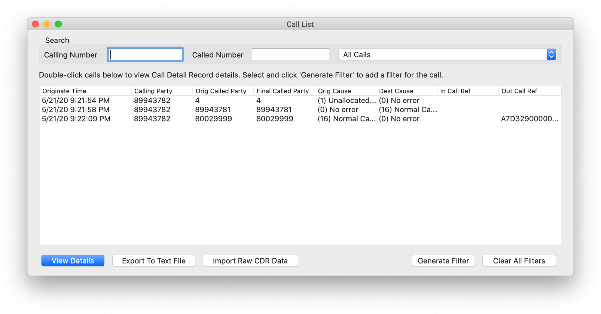
Figure 4-50 TranslatorX Call List
From the call list, you have a couple of options. You can select a call and either double-click it or click the View Details button on the screen. Either way, you see a window that looks similar to Figure 4-51.

Figure 4-51 TranslatorX CDR Details Window
This window shows you the call details. You can see that there is no destination for the call, and the call never connected. You can also see that the only digit dialed was 4. How can you see more details like the ones you saw in the SDL trace file? Return to the Call List window, select the call you want to troubleshoot, and click the Generate Filter button to filter the messages and include only messages relevant to this particular call. Figure 4-52 shows what the main TranslatorX window looks like when you do this.
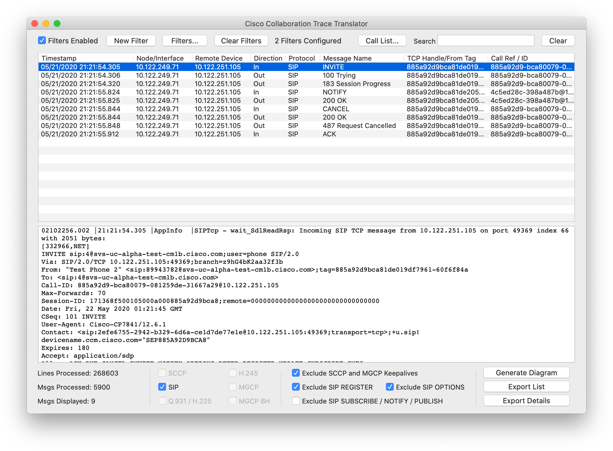
Figure 4-52 TranslatorX Window with One Call Filtered
If you click on a message in the top pane of the window, TranslatorX shows you the decoded message in the bottom pane for the message selected. In this case, you can see that the INVITE is selected, and the full SIP message is shown in the bottom pane. At any time, you can double-click on a message to open the SDL trace file where that message was found to be taken to the exact point in the log file that contains that message. For example, if you double-click on the INVITE, a new window appears that looks like the one shown in Figure 4-53.
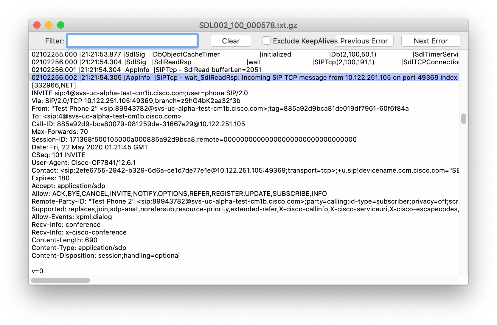
Figure 4-53 TranslatorX Raw Trace File View
You still have to rely on the raw SDL trace files to see things like digit analysis results and any kinds of transformations being applied by digit analysis, but TranslatorX makes this process easier by taking you to the exact point in the trace associated with a particular event, such as a SIP INVITE.
You can click the Generate Diagram button in the bottom-right corner to view a ladder diagram for the call. For the call we have been examining, the ladder diagram is not very exciting because the call failed due to the number dialed being an invalid number. Let’s take a look at a ladder diagram for the second call we looked at previously in the SDL trace file, where the call was routed through the route list to a SIP trunk. Figure 4-54 shows the first part of the message sequence diagram for this call.
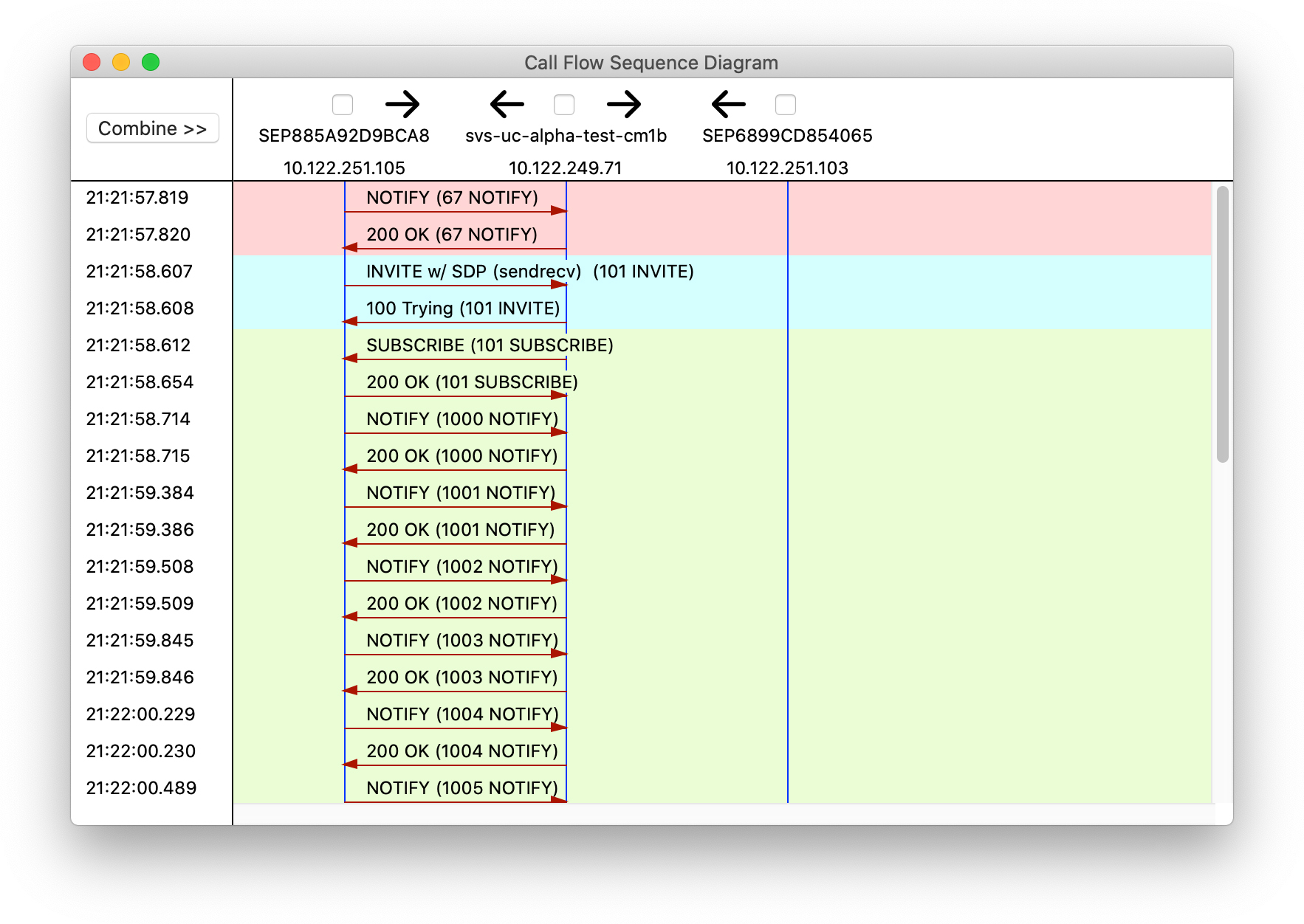
Figure 4-54 TranslatorX Message Sequence Diagram
You can see that the call originates from an IP phone with a NOTIFY message followed by a SIP INVITE. You can click on the message on the diagram to look at the details of the message at any time. For example, if you click the INVITE, you see something similar to the information shown in Figure 4-55.
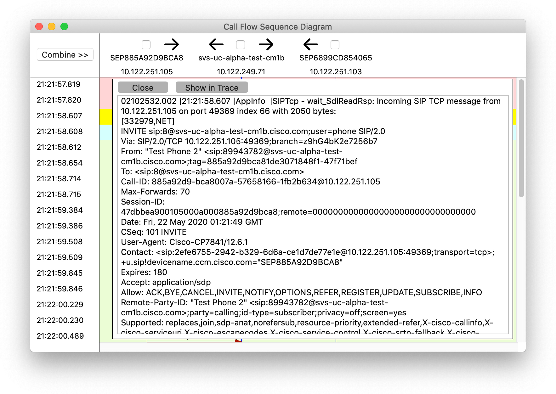
Figure 4-55 TranslatorX Message Sequence Diagram with INVITE Selected
If you want to be taken to the place in the trace file where the INVITE occurred, you can click on the Show in Trace button to be taken to the raw SDL trace file. If you scroll through the ladder diagram, you can see the remainder of the call flow, as shown in Figure 4-56.

Figure 4-56 TranslatorX Message Sequence Diagram, Continued
The ladder diagram enables you to easily visualize where the call originates from and where it is destined to. You can click on the outbound SIP INVITE to examine the calling and called party number information being sent to the far-end destination to ensure that it is as expected.
Note
In-depth SIP troubleshooting could fill a book of its own. What we have covered here should give you enough information to diagnose most call routing–related issues.
![]()
Collaboration Solutions Analyzer
The last tool available to help you diagnose call routing–related issues is the Cisco Collaboration Solutions Analyzer (CSA). At the time of this writing, the tool can be found at https://cway.cisco.com/csa. Make sure you have first navigated to cisco.com and logged in with a valid Cisco.com account before attempting to access the CSA website. CSA contains several modules. The module we discuss here is the Log Analysis module. When you visit the CSA website, click on the Log Analysis button, and you are presented with a window that allows you to upload a set of log files. For CSA, you must package all the log files together, so after downloading the files from Unified CM using Collect Files in RTMT, use a compression utility to create a single archive of the contents of the entire folder.
After you upload the files to CSA, the tool should detect the files with CUCM as the product type, as shown in Figure 4-57.
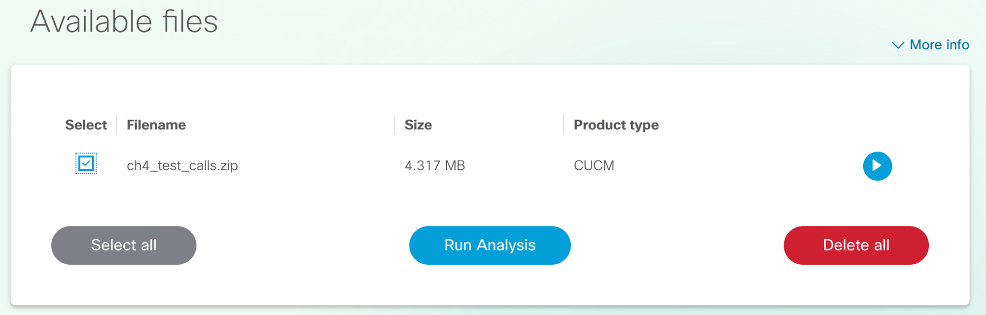
Figure 4-57 Collaboration Solutions Analyzer Available Files
You can select the checkbox next to the files and either click the Run Analysis button or click the Play button on the right side to analyze the logs. Depending on the number of log files uploaded, CSA might take some time to do the processing.
CSA processes not only the SDL traces but also some additional logs that are included in the log file download called the calllogs files. These files contain summary data about SIP messages and feature invocations, but do not include details of the messages. Because CSA reads the calllogs files, it includes many calls that do not have corresponding SDL traces. Those calls show up on the list of calls with a red x in the right-most column, labeled Within SDL, as shown in Figure 4-58.
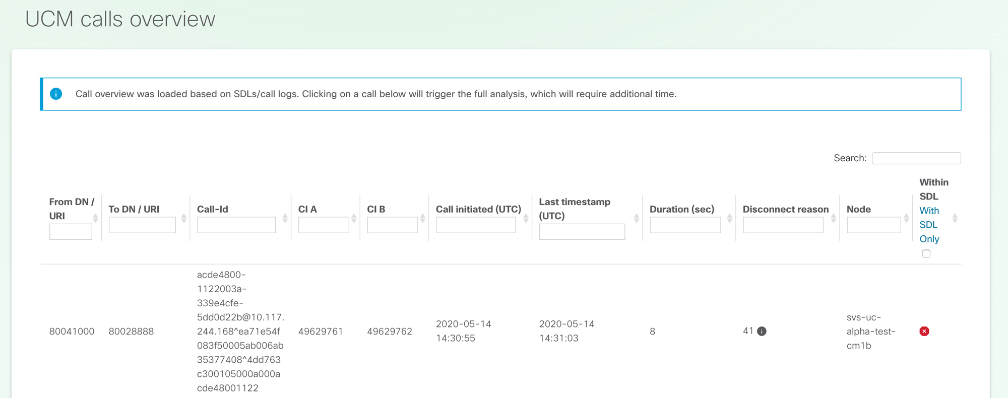
Figure 4-58 CSA Call List with No SDL
You need to check the With SDL Only box in the Within SDL column. Once you have selected this box, the list shows only calls that are present in the SDL trace files. As shown in Figure 4-59, after you. select this checkbox, you see the same list of three calls that you saw in RTMT and in TranslatorX.

Figure 4-59 CSA Call List Showing Only Calls with Messages Found in SDL Traces
You can select a call from the list and wait for CSA to perform additional processing on the call. After processing, you see a Call Detail section with four tabs: Call Leg Info, Signaling, Ladder Diagram, and Annotated Logs.
The Call Leg Info tab provides an overview of the parties involved in the call, DTMF capabilities of each party, whether a transcoder or MTP was required for the call, and region bandwidth information. The ladder diagram is similar to the one presented in TranslatorX. Figure 4-60 shows a portion of the ladder diagram for a call in CSA.

Figure 4-60 Ladder Diagram in CSA
As with TranslatorX, you can click on a SIP message to view the details of the message. Perhaps the most useful feature in CSA is the Annotated Logs tab. This tab gives you an abbreviated, annotated view of the most important lines in the SDL trace file and filters out a lot of the noise that is not relevant in day-to-day troubleshooting. For example, Figure 4-61 shows a portion of the annotated logs output for the same call you looked at in the raw SDL trace files.

Figure 4-61 CSA Annotated Logs
Notice that CSA indicates the SIP NOTIFY messages (which you can click on to expand and see more detail) and the subsequent digit analysis matches as each digit is presented. You can then finally see the digit analysis results, just as you did in the SDL trace file. The annotated logs also show you the route list selection and device selection, as shown in Figure 4-62.
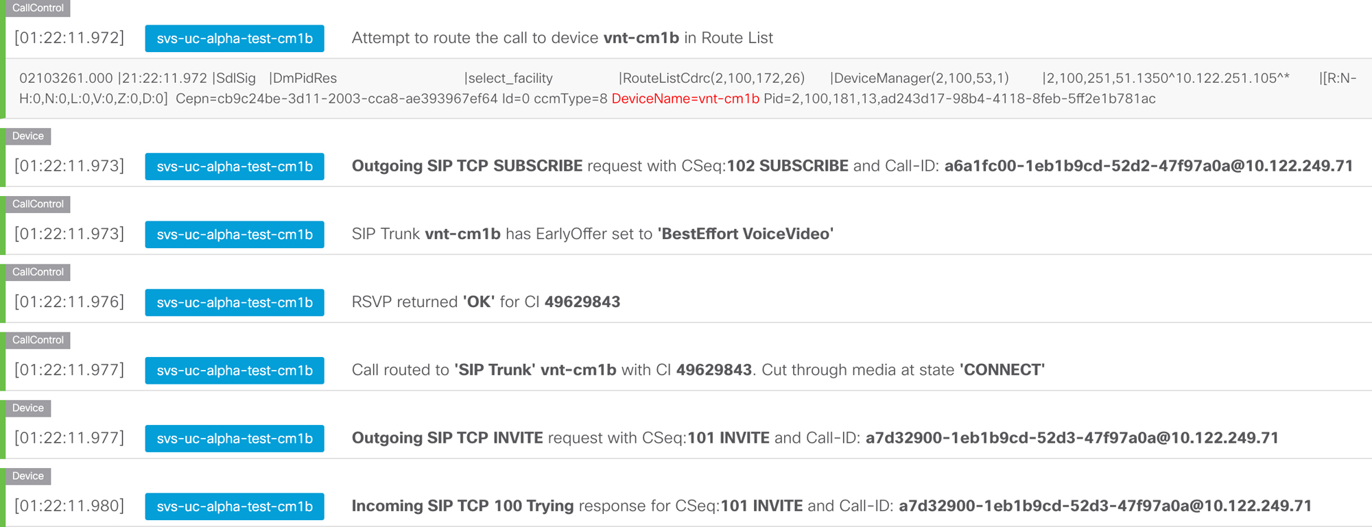
Figure 4-62 CSA Annotated Logs, Continued
CSA is a powerful tool that allows you to analyze Unified CM log files to diagnose call routing as well as other potential issues with a Unified CM cluster. We suggest placing some calls in your environment and using RTMT, TranslatorX, and CSA to analyze them so you can become familiar with these tools.
Now that you have completed this chapter, you should have a solid understanding of how to configure and troubleshoot call routing in Unified CM for both numeric and alphanumeric patterns, including the ability to translate and transform calling and called party numbers and route calls through route patterns, route lists, route groups, hunt pilots, hunt lists, and line groups. You should have a good understanding of why ILS is needed for intercluster routing and the advantages of using Global Dial Plan Replication. Finally, you should have an understanding of the tools available for diagnosing and troubleshooting a variety of call routing–related problems.
Exam Preparation Tasks
As mentioned in the section “How to Use This Book” in the Introduction, you have a couple of choices for exam preparation: the exercises here, Chapter 11, “Final Preparation,” and the exam simulation questions in the Pearson Test Prep software online.
Review All Key Topics
Review the most important topics in the chapter, noted with the key topics icon in the outer margin of the page. Table 4-6 lists these key topics and the page number on which each is found.
![]()
Table 4-6 Key Topics for Chapter 4
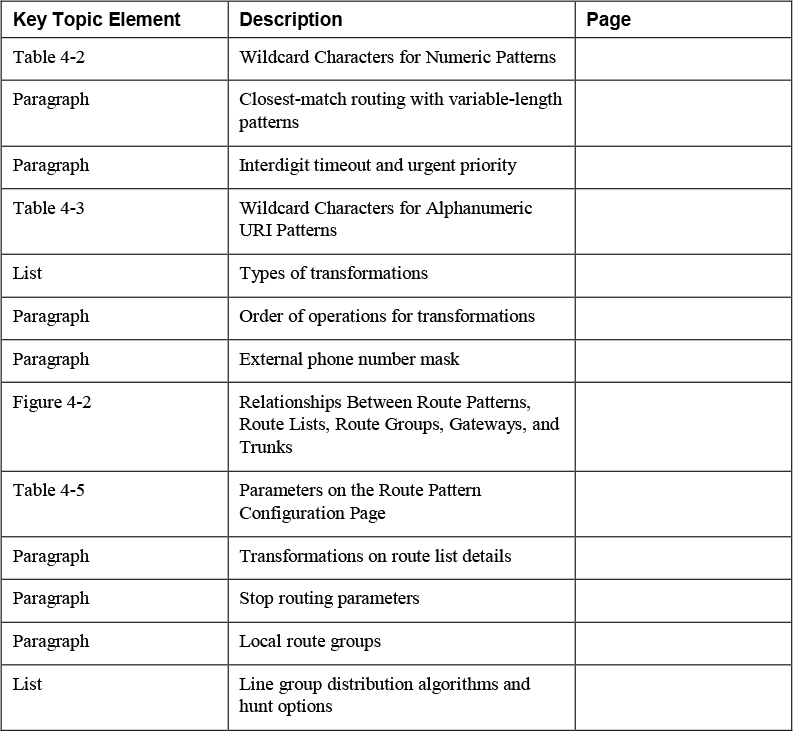
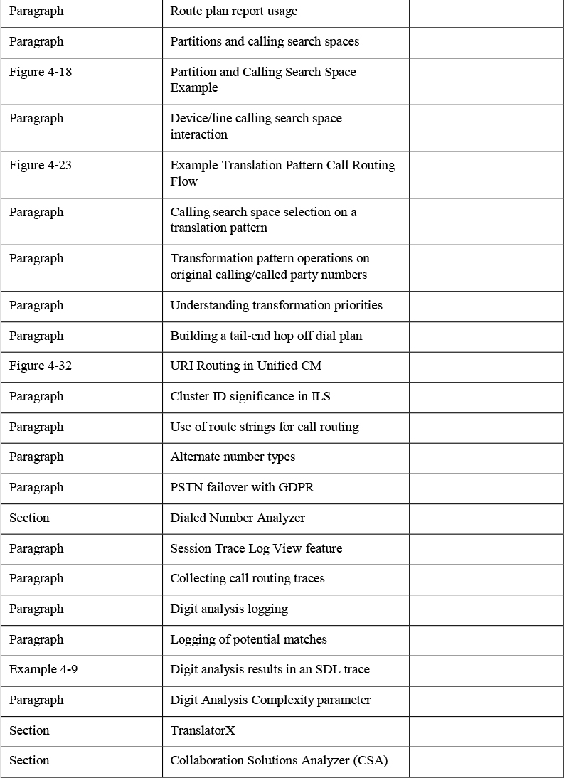
Complete Tables and Lists from Memory
Print a copy of Appendix C, “Memory Tables” (found on the companion website), or at least the section for this chapter, and complete the tables and lists from memory. Appendix D, “Memory Tables Answer Key” (also on the companion website), includes completed tables and lists to check your work.
Define Key Terms
Define the following key terms from this chapter and check your answers in the glossary:
pattern
alphanumeric uniform resource identifier (URI) dialing
Intercluster Lookup Service (ILS)
Global Dial Plan Replication (GDPR)
Real-Time Monitoring Tool (RTMT)