Creating a new layout document
Modifying layout settings
Working with pages and spreads
Creating Master pages
Using layers
Adding auto numbering
Using rulers, grids, guides, and frames
Importing artwork
Using artwork versions
Working with the Links palette
Anchoring objects in InDesign
Imagine the process of creating a sidewalk. The first step is to create the forms that define the edges of the sidewalk. If you create these before you mix the cement, the cement easily flows into the right location and the job is completed rather quickly. However, if the forms are not straight or secure, the cement flows outside the bounds and finished work won't be smooth and straight. Similarly, if you complete the layout design beforehand, the text and images flow easily into the document in the correct positions.
This chapter covers the basics of creating a useful layout in InDesign. The initial settings for a layout document are set when you create a new document. You can use the Pages palette to add and delete pages, rearrange pages, and create spreads and Master pages. Master pages provide a convenient way to update similar content on many pages at once. Several other useful layout objects include rulers, grids, guides, and frames. Using these objects, you can quickly lay out all the objects that are included in a page before the content is ready. The content can then be easily placed within these frames when it's ready.
After you create a layout, you may need to modify it. For example, embedding all the images you use in your layout in an InDesign document may result in a large file that's difficult to handle. However, you can place links to the larger original artwork elements within InDesign to make your file more manageable and embed smaller elements. You also can anchor graphics to a section of text so the graphic moves as the text moves.
This chapter shows you how to access links via the Links palette to see what links you need to relink, move, update, or embed, as well how to update edited image files.
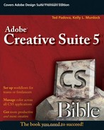
You establish layouts in InDesign when you create a new document using the New Document dialog box that opens when you create a new document. It includes settings for defining the number of pages, the page size, the orientation, the margins and columns, and the bleed and slug areas. You can save these settings and reuse them to create other new documents.
You initially specify basic layout design in InDesign when you first create a new document. Choose File
Directly below the Document Preset list is an Intent list. This option lets you choose to create a document for Print or for the Web. Selecting either option automatically changes the Page Size and Orientation settings.
Using the New Document dialog box, you can specify the total number of pages that make up the layout. The Facing Pages option causes left and right pages to face one another. If this option is disabled, each page stands alone. The Master Text Frame option causes a text frame to be added to the Master.
The following options on the New Document dialog box control the page layout of your new document:
Page Size options: The Page Size drop-down list includes several common paper-size options including Letter, Legal, Tabloid, Letter – Half, Legal – Half, A5, A4, A3, B5, US Business Card, Compact Disc, several default Web page sizes, and Custom. Selecting any of these sizes automatically adjusts the Width and Height settings. The Custom option lets you manually set the Width and Height values.
Tip
You can add your own options to the Page Size menu by saving a preset using the Save Preset button. This opens a dialog box where you can name the new preset.
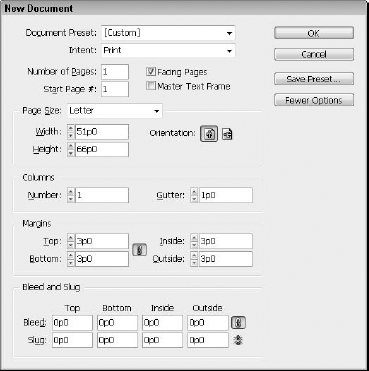
The Orientation icon buttons include Portrait and Landscape options. A Portrait orientation has a height greater than its width, and a Landscape orientation has a larger width than height. Clicking the unselected icon button swaps the Width and Height values. Figure 22.2 shows two new Letter-sized documents. The left one has a Portrait orientation, and the right one has a Landscape orientation.
Note
Within the New Document dialog box, you can enter "8i" to specify 8 inches regardless of the unit of measurement that you're using.
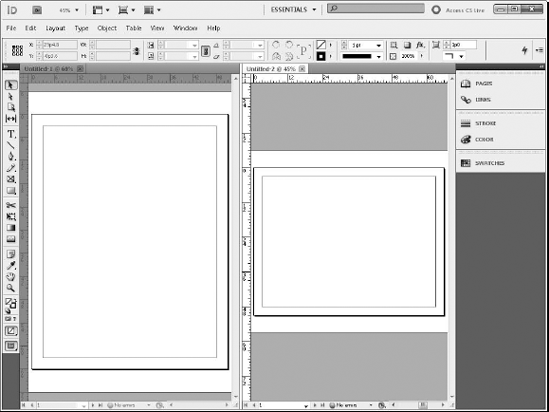
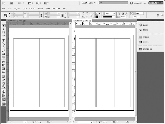
Column options: The Columns section of the New Document dialog box lets you specify the number of layout columns used in the default master page. The gutter is the space between each column. Figure 22.3 shows two new layouts. The left layout has two columns, and the right layout has three columns.
Margins options: Margins are the space between the edge of the paper and the page content. Guides, which appear where you specify margins, denote this space. You have four margin values correlating to each edge of the page—Top, Bottom, Left, and Right. If you select the Facing Pages option, the Left and Right margins become the Inside and Outside margins. Between the margin values is an icon button with an image of a link on it. Clicking this button sets all settings to equal values.
Bleed and Slug: Clicking More Options expands the dialog box to reveal Bleed and Slug settings. The Bleed and Slug areas of a page extend beyond the edges of the page. They contain information and guides to help the printer. The Bleed includes guides on how far to extend a color or image beyond the edge of the page in order to ensure that the color or image runs all the way to the paper edge after trimming. The Slug area displays printer instructions and other information that isn't intended to be part of the printed page. Bleed and Slug values include settings for each margin and an icon button to make all values equal.
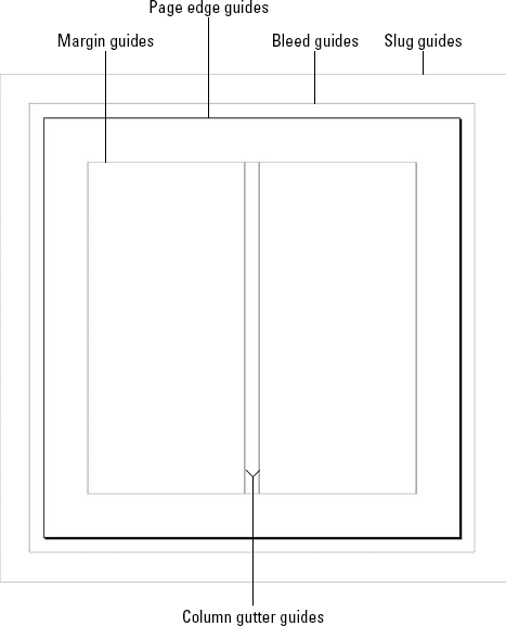
When you create a new page, several guides denote the various page-layout settings. These guides are color-coordinated, with the margins represented by pink-colored guides, the columns and gutters represented by purple guides, the Bleed areas represented by red guides, and the Slug area represented by light-blue guides. The page edges are displayed as black guides. Figure 22.4 shows the various guides.
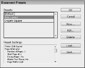
If you find yourself changing the default layout options every time you create a new document, you may benefit from a document preset. When you make the setting changes, click Save Preset and a simple dialog box appears where you can name the new preset.
After it's saved, the new preset is available for selection from the Document Preset list at the top of the dialog box. Selecting the preset name changes all the settings automatically. Saved presets also are available by choosing File
Tip
Holding down the Shift key while selecting a preset from the File
Changing the Default Layout Settings
When you first create a new document, the default layout settings are used. You can alter these default settings by changing the settings in the Document Setup dialog box (choose File
If you don't have any other documents opened when you make changes to these dialog boxes, and you create a new document, the default layout updates.
Choosing File
You can save and load document presets from the hard drive. These presets are saved using the DCST extension. These presets can be shared among team members to insure a consistent layout among several different design teams in an organization.
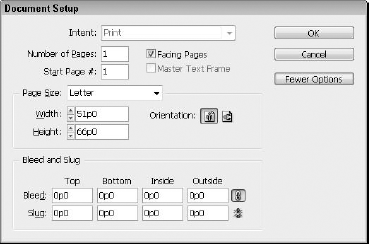
If you discover that you need to change one of the layout settings for the entire document, you can revisit most of the same settings in the New Document dialog box by opening the Document Setup dialog box. Choosing File
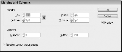
You use the Margins and Columns dialog box to change the margins and columns settings, shown in Figure 22.7. You open this dialog box by choosing Layout
To change the margin and column settings for all pages in the document, select all pages in the Pages palette before opening the Margins and Columns dialog box. An easier method is to make the change on the master page.
Layouts created with InDesign CS5 can be exported using several different formats, including Interactive PDF, standard PDF, EPS, Flash CS5 Professional (FLA), Flash Player (SWF), InDesign Markup (IDML), JPEG, and XML. Many of these export options have been improved in CS5. To export a document, choose File
Warning
Be aware that if you try to open an exported CS5 document, some new CS5 features included in an exported file may not be visible when the file is opened in the earlier versions.
If you have some existing layouts created in either Quark or PageMaker, you'll be happy to know that these layouts can be opened and converted to InDesign files. Choose File
Tip
Files created using QuarkXPress 5.0 and 6.0 can be opened in InDesign by first saving them using the QuarkXPress 4.0 format and then opening them in InDesign.
When a Quark or PageMaker file is opened in InDesign, the layout elements are converted to native InDesign elements. Note that although most elements are comparable between the different systems, there are some differences that may cause problems. For example, the color profiles in Quark aren't used in InDesign and are ignored during the conversion. It is also common for kerning, tracking, and line ends to change.
After establishing a layout, you use the Pages palette to work with the different pages and/or spreads. Using this palette, you can select, target, rearrange, delete, or add pages and/or spreads. The Pages palette also provides access to Master pages.
The Pages palette, shown in Figure 22.8, provides a high-level view of all the pages in the current document. It displays each page and spread as an icon. You use it to quickly select, add, and delete pages as well as to apply a Master document to specific pages. You can open the Pages palette by choosing Window
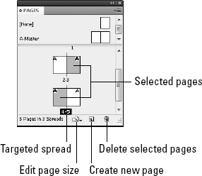
Figure 22.8. The Pages palette shows icons for all pages, spreads, and Masters in the current document.
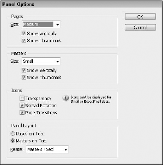
You can change the size and position of icons in the Pages palette using the Panel Options palette menu command. This dialog box, shown in Figure 22.9, lets you set an icon size for Pages and Masters to be Small, Medium, Large, Extra Large, or Jumbo. You also can select to display the icons Vertically or Horizontally and enable or disable the thumbnails. If the Show Thumbnails option is selected, then a small representation of the current page is displayed. The final option lets you place the Pages or the Masters at the top of the palette.
There are also some settings for controlling how the page icons are displayed including whether to show if there's transparency on the spread, if the spread view is rotated, and whether there are page transitions set for exporting to PDF and/or SWF.
You can easily select and target pages and spreads by using the following actions in the Pages palette:
Click: This selects the page or spread icon.
Double-click: This targets the page or spread or moves it to the center of the interface.
Holding down the Shift key while clicking on the page icons: This selects multiple pages or spreads.
The Pages palette icons are highlighted for all selected pages. When you apply certain actions, such as applying a Master or adding page numbers, they affect all selected pages.
Targeted pages are the pages that are currently active, and they're the pages that receive any newly created objects or any object that is pasted from the Clipboard. You also can identify the targeted page because it is the page whose ruler is not dimmed. Dimmed rulers are easiest to see in the vertical ruler. You can target only one page or spread at a time. The targeted page in the Pages palette has its page numbers highlighted.
Tip
You also can select and target pages using the Page Number drop-down list located at the bottom-left corner of the interface.
The Layout menu includes several commands for select pages and spreads:
Layout

Layout
Layout
Layout
Layout
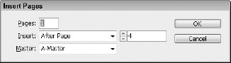
You add pages to a new document using the Insert Pages palette menu command, which opens the Insert Pages dialog box, shown in Figure 22.10. This dialog box lets you add a specified number of pages to the current document. The Insert options include After Page Number, Before Page Number, At Start of Document, and At End of Document. You also can select a Master page to use.
Note
You can add pages to the current document by entering a high value in the Number of Pages field for the Document Setup dialog box. The new pages are added onto the end of the current pages.
You also can add pages to the current document by clicking on the Create New Page icon button at the bottom of the Pages palette.
In addition to inserting pages, the palette menu includes several other menu commands that are applied to the selected pages. The Duplicate Page (or Duplicate Spread, if a spread is selected) palette menu command creates a duplicate of the selected page (or spread). This duplicate also includes a duplicate of the page contents.
The Delete Page (or Spread) palette menu command removes the selected pages from the current document. If these pages contain any content, a warning dialog box appears, asking if you're sure about the deletion. You also can delete selected pages by clicking on the Delete Selected Pages icon button at the bottom of the Pages palette.
In addition to the palette menu, the Pages palette also is used to rearrange pages and spreads. By selecting and dragging the page icons in the Pages palette, you can rearrange the page order.
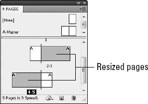
If you select the Edit Page Size button at the bottom of the Pages palette, you can choose a new page size that is applied to the selected pages. The available sizes include the same options that are found in the New Document dialog box, including Letter, Legal, Tabloid, and so on. The Custom Page Size option opens a dialog box where you can specify the resolution. Once applied, the new relative page size is displayed in the Pages palette, as shown in Figure 22.11.
A Master is a page that holds all the elements that are common for several pages. It can include items such as page numbers, headers and footers, logos, and so on. All the items placed on the Master show up on the pages that the Master is applied to.
Each new document includes a single Master called the A-Master. This Master is selected from the top of the Pages palette, shown in Figure 22.12. You create and apply new Master pages to selected pages, so a document may have several Master pages applied to different pages. Each page may only have a single Master applied to it.
Tip
You also can select Master pages using the drop-down list located at the bottom left of the document window. This drop-down list includes all pages and named Masters.
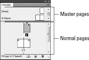
Figure 22.12. The top of the Pages palette holds the Master pages unless you change the preferences as mentioned above.
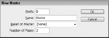
To create a new Master page, select the New Master panel menu command in the Pages panel. This opens the dialog box shown in Figure 22.13, which allows you to give the Master document a Prefix and a Name and to select another Master to base it on. You also can select the number of pages in the Master spread.
Tip
By basing all newly created Masters on a single main Master page, you can make changes to the main Master page, and all other Masters based on this main Master inherit the changes also.
New Masters also are created by dragging a page or spread from the Pages palette to the Masters section at the top of the Pages palette. If the dragged page contains any objects, those objects become part of the Master page. If the dragged page has a Master applied to it, the new Master is based on the applied Master.
You can change the Master options by selecting the Master and choosing the Master Options palette menu command. This opens the Master Options dialog box again.
You can delete Master pages, like normal pages, by dragging them to the trash icon button at the bottom of the Pages palette or by selecting the Delete Master Spread palette menu command. Selected pages are deleted by selecting Delete Master Page option from the palette menu, dragging the Master page to the Delete Selected Pages icon at the bottom of the palette, or clicking the Delete Selected Pages icon.
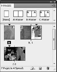
The Pages palette makes it easy to apply Masters to different pages and spreads. Simply drag the Master that you want to apply and drop it on the icon in the Pages palette of the page or spread that you want to apply it to. Masters should be applied only to spreads with the same number of pages. The Pages palette displays the prefix for the Master applied to it in the upper outside corner of the page, as shown in Figure 22.14. This figure also shows the Pages palette with the Show Thumbnails options enabled.
If you select multiple pages and Option/Alt+click on a Master page, that Master page is applied to all the selected pages. You also can select the Apply Master to Pages palette menu command. This action opens a simple dialog box where you can select a Master and type in the page numbers of the pages that you want to apply the Master to. To include multiple contiguous pages, use a dash symbol (for example, 4-7).
If a page or a spread is selected, you typically can't edit the objects that are part of the Master. However, if you override the Master object, you can change any and all attributes of the object with no restriction, such as its stroke, fill, and transformations. If some attributes on the overridden object are not changed, then changes to the Master item will still ripple down to the unchanged object. If you need to change the Master object even more, you can detach it from the Master page. Detaching an object from its master cuts all ties between the two objects.
Overriding all Master objects on the selected page is accomplished using the Override All Master Page Items (Alt+Shift+Ctrl+L on Windows, Option+Shift+
If you want to edit only a single Master object on the selected page or spread, you can hold down the Shift+
All Master page objects are detached using the Detach All Objects from Master palette menu command.
Note
Be careful when detaching pages from a master. The process works in levels. The first level is override, applied singly or to all master page objects in a spread. At this point, individual changes can be applied to objects, but any unchanged qualities are still controlled by the master page object. Overrides can be removed later if desired. The second level is to detach an overridden object. When you detach an overridden object from the master, it severs all ties to the master object. You cannot detach without first overriding. You cannot detach all unless something has been overridden, and then only the overridden objects are detached; non-overridden objects are left alone.
All page objects that are provided by a Master may be hidden or shown by choosing the Show/ Hide Master Items menu from the panel menu. Master page objects are displayed with a dotted line on the document page. Master page items can be locked so they cannot be overridden. To lock a master page item, simply select the item and make sure that the Allow Master Item Overrides on Selection option in the Pages palette menu is disabled.
Document pages as well as Master pages have layers. Layers are used to organize page objects and to control which objects appear above other objects. Objects placed on a higher layer appear on top of objects placed on a lower layer. Both document pages and master pages share the same layers, layer stacking order and interaction. Master objects on a specific layer actually lie beneath all objects on the same layer on a document page.
Note
More details on working with layers can be found in Chapter 23.
To the left of each layer name is an expand/contract arrow icon that you can click to reveal all the individual objects that are included on the selected page. You can set the stacking order of objects on a page by dragging their position in the Layers palette. Individual objects also can be moved between different layers, hidden, and locked using the Layers palette.
All layers are displayed in the Layers palette, shown in Figure 22.15. Each layer has a name and a color associated with it. All objects are highlighted with their layer color when selected. The layer highlight color is also shown when no object is selected and View
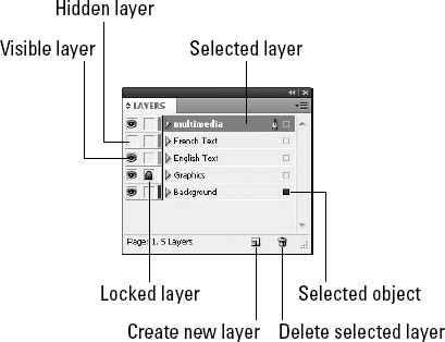
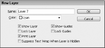
All new documents include a single layer named Layer 1. New layers are created using the New Layer palette menu command or by clicking the Create New Layer button at the bottom of the Layers palette. The New Layer menu command opens a dialog box, shown in Figure 22.16, where you can enter a name, choose a color, and select other options.
By default, all Master page objects appear behind the document objects, but you can force objects on a Master page to appear on top of the document objects by assigning a higher layer to the Master objects.
If you've already created an object on a Master page that has a lower layer number than the document object that you want to place it on top of, you can create a higher layer in the Layer palette by selecting the New Layer palette menu command or by clicking on the Create New Layer button at the bottom of the Layers palette. Then select the objects that you want to move to the new layer and drag the small square icon to the right of the layer name to the new layer. The frame edge of the object changes colors to match the new layer.
Note
You also can move objects between layers by choosing Edit
Page numbering automatically updates as you rearrange, add, or delete pages from the current document. Auto page numbers may be added to a Master page or to a normal page.
To add auto numbering to a page, select the page or Master and drag with the Type tool to create a text object. Then type any text that you want to appear before the page number. Choose Type
Note
For more information on formatting text, see Part IV.
By default, auto numbering calls the first page "page 1," the second page "page 2," and so on, but you can change the number formatting to Roman numerals or letters and also start with a number other than 1 using the New Section dialog box, shown in Figure 22.17. Open this dialog box by choosing Layout
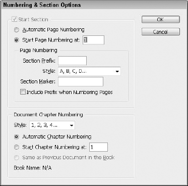
To define a section, choose the first page for the section in the Pages palette; then open the Numbering & Section Options dialog box, and choose the numbering options. Enabling the Start Section option creates a new section. You also can specify a Section Prefix and a Section Marker. The Section Prefix displays along with the page number when you enable the Include Prefix When Numbering Pages option. You can add the Section Marker to the numbering text object by choosing Type
Note
You also can use the specified numbering style in the table of contents and the index pages using section markers. The Layout
When the dialog box is closed, the Pages palette displays the page numbers using the selected numbering style and a small down-arrow icon appears above the first page of each section in the Pages panel. Double-clicking on the section arrow icon in the Pages palette, choosing the Numbering & Section options from the pop-up menu, or by selecting this command from the palette menu, opens the Numbering & Sections dialog box. You can add several sections to the current document.
Note
You can set InDesign to display absolute page numbers or section page numbers in the Pages palette using the Page Numbering option in the General panel of the Preferences dialog box.
After you create a layout, you can enhance various elements that you want to appear consistently throughout the document. For example, you can quickly add a sidebar element to designated pages by creating a guide that identifies the placement of the element. Using rulers, grids, and guides provides an effective way to enhance a layout.
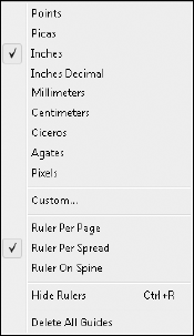
Rulers are positioned on the left side and above the pasteboard and are consistent to the page regardless of the amount of zooming. If you right-click on the ruler, you can change its measurement units using the pop-up menu shown in Figure 22.18. The options include Points, Picas, Inches, Inches Decimal, Millimeters, Centimeters, Ciceros, Agates, Pixels, and Custom.
Tip
If the rulers aren't visible, you can make them appear by choosing View
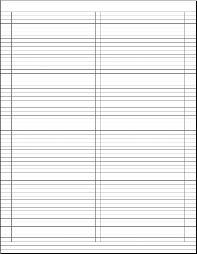
InDesign has two different types of grids that can overlay the document. The Baseline Grid, shown in Figure 22.19, includes horizontal lines used to mark text baselines. It's confined to the page.
The Document Grid type, shown in Figure 22.20, is made up of small grid squares and overlays the entire art board.
Both of these grids are made visible by choosing View
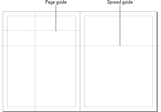
Guides are simply lines that extend from the ruler, providing a visual boundary for page objects. InDesign uses two different types of guides. Page guides are seen only within the page, and Spread guides run across the entire spread including the art board.
You create a Page guide by clicking on a ruler and dragging onto the page. Holding down the
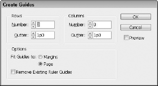
You create a series of consistent guides using the Create Guides dialog box, shown in Figure 22.22, which you access by choosing Layout
You can select and move guides after they're created. To lock all guides so they can't be moved accidentally, choose View
Guides are actual objects in InDesign and belong to a specific layer. As such, they are hidden and/or locked along with its respective layer. Guides can also be selected, distributed, copied, and pasted.
Tip
Guides can be selected and exported as a snippet to be used elsewhere.
With grids and guides in place, another helpful object is a layout frame. You create frames, which act as placeholders for graphics or text, using any path or object in the Toolbox including Rectangles, Ellipses, Polygons, objects drawn with the Pen tool, or any freehand drawn shape.
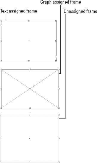
To create a frame, select a drawing tool in the Toolbox, such as the Rectangle Frame tool (F) and drag in the page to create a frame. With the frame selected, you can specify what type of content the frame holds by choosing Object
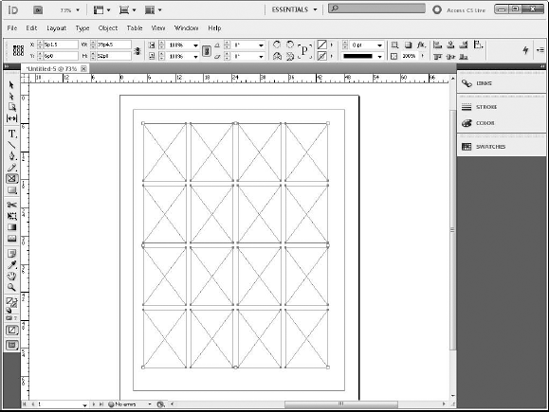
Graphic frames have an X through their center, and text-assigned frames have ports that thread multiple frames, as shown in Figure 22.23.
When creating a frame with any of the available drawing tools, including the Type tool, you can press the up or right arrow keys to divide the current frame space into a grid of frames. The arrow keys need to be pressed while the mouse button is still pressed. You also can use the Shift key to divide the frames into perfect square or circle arrays of frames. Figure 22.24 shows a perfect array of rectangular frames created by pressing the up and right arrows four times each while dragging to create the frame. You also can use the down and left arrow keys to decrease the number of rows and columns.
These same arrow keys can be used to create an array of objects when creating a clone of an object by dragging with the Option/Alt key pressed. To do this, simply select and begin dragging an object with the Option/Alt key pressed, and then release the Option/Alt key and press the arrow keys to create equally spaced rows and columns of the object. Release the mouse button when finished.
Note
If this method of using the arrow keys to create a grid of objects is used with the Type tool, the objects are automatically threaded together.
Within the Tools palette, you can find the Gap Tool (U). Using this tool, you can drag to change the amount of white space that exists between layout elements by simply dragging with the tool. When you drag the Gap Tool over the top of a section of white space, a double-headed arrow cursor appears. If you drag while this cursor is visible, the element located on one side of the white space becomes active and can be repositioned by dragging while the mouse button is pressed. This also works if multiple objects are on either side of the gap.
If you press the Shift key while dragging with the Gap Tool, the changes are limited to only those elements closest to the cursor. Dragging with the Command/Ctrl key pressed causes the gap to widen by pushing elements on both sides away. Pressing the Option/Alt key while dragging causes the elements on either side to move with the gap in the direction of the drag.
Tip
You can access the Gap Tool while the Selection Tool is active by pressing the U key while using it.
Figure 22.25 shows the results of using the Gap Tool. When you drag the white space between the text and the above graphics, the text moves down and the graphics stretch.
As you create a layout with frames, it's often helpful to import a stub image, which acts as a placeholder for final artwork, with the correct dimensions from Photoshop and Illustrator. After importing stub images, you can create the artwork using either Photoshop or Illustrator, and if you establish links between the two packages, the artwork can be updated dynamically.
Note
Stub objects are frequently called FPO objects, which stands for For Placement Only.
The File
You can import Photoshop artwork into a selected frame by choosing File
Note
Chapter 2 includes a good example of placing an imported file into InDesign.
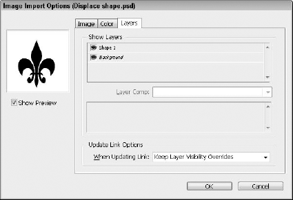
Figure 22.26. The Image Import Options dialog box includes panels for selecting the Alpha Channel and Color Management profiles.
The Apply Photoshop Clipping Path and the Alpha Channel drop-down list options are enabled if the imported object includes a clipping path and/or an Alpha Channel. For imported images that include an Alpha Channel, you can select the Transparency or Graduated Transparency option. PSD files also give you the option to control which layers are visible. If the file includes some Layer Comps, you can choose which ones to import.
Placed files also can benefit from the Proportional Placing features. When a graphic file is ready to place, you can click-drag and InDesign constrains the dimensions of the frame you create to match the proportions of the file being placed.
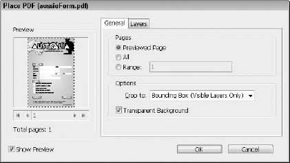
Artwork created in Illustrator and PDF files that are placed within a selected frame in InDesign open the Place PDF dialog box if Show Import Options is enabled. This dialog box, shown in Figure 22.27, includes two separate panels: General and Layers. The General panel includes settings that let you select to place the Previewed Page, All pages, or a Range of pages from the PDF file; it also includes options to set a cropping option and to make the background transparent. The Layers panel lets you see all the layers that are in the imported artwork. For each layer, you can select to Use PDF's Layer Visibility or to Keep Layer Visibility Overrides. If the imported Illustrator file includes bleed values, InDesign recognizes and uses these values.
Flash files are placed within an InDesign document using the File
Warning
Placing SWF files in InDesign is tricky. There are a number of Flash features that InDesign cannot handle.
You may open and edit artwork created using Photoshop and/or Illustrator in their original application by right-clicking the image and choosing Graphics
Tip
Holding down the Option/Alt key while double-clicking on a placed source file opens the file in its native application.
Because assembling a layout is critical, next we walk through an example that takes you through the steps to create a sample layout and to add auto page numbering to a Master page in InDesign.
STEPS: Creating an InDesign Layout
Create a new document. Within InDesign, choose File
Set the Bleed and Slug settings. If the Bleed and Slug section isn't visible, click More Options. Set the Bleed values to 0, and click the Make All Settings the Same button. Set all Slug values to 0. Figure 22.28 shows the New Document dialog box with the appropriate settings. Click OK to create the new document.
Edit the Master spread. In the Pages panel, select and target the A-Master spread by double-clicking its title. The spread icons are highlighted in the Pages panel, and the spread is centered in the interface. Select the Master Options for "A-Master" command from the Pages panel menu. This opens the Master Options dialog box for the A-Master spread. Change the Prefix to S and the Name to SpreadMaster. Click OK to close the dialog box.
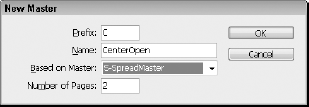
Create a New Master spread. In the Pages palette, select the New Master palette menu command. The New Master dialog box opens, shown in Figure 22.29. Enter a Prefix value of C, enter a Name of CenterOpen, and set the spread to Based on the S-SpreadMaster Master. Click OK to close the dialog box.
Apply the Master spreads to the pages. In the Pages palette, drag the Master page named None to the first page. Then drag the C-CenterOpen Master to the spread in pages 2 and 3. The remaining spreads already have the S-SpreadMaster Master applied to them.
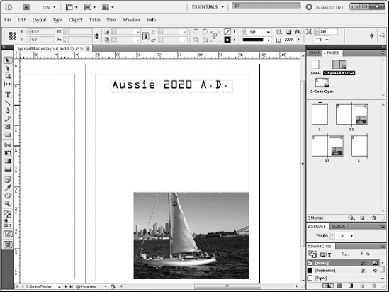
Adding content to the Master spreads. Double-click the S-SpreadMaster to select and target it. Create some objects, and position them within the Master spread. Figure 22.30 shows the Master spread with several content items added to it.
Add Auto Page Numbering. With the Type tool, drag to create a small text object in the upper-left and upper-right corners of the Master spread. With the text object selected, choose Type
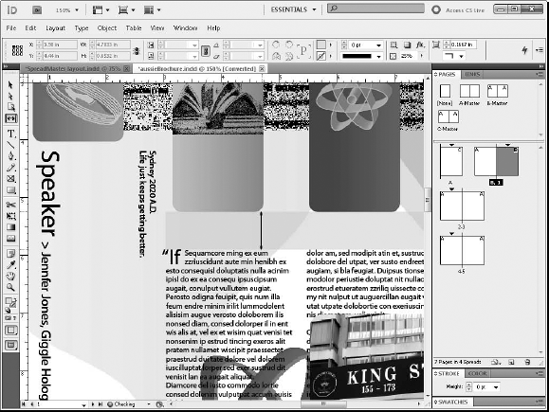
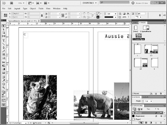
Place artwork on the secondary Master. Double-click the title for the C-CenterOpen Master in the Pages palette. This selects and targets the second Master spread. With the Secondary Master spread selected and targeted, choose File

When you place images in an InDesign document, the image file isn't copied into InDesign. Instead, a lower-resolution version of the image displays allowing you to position the image in the layout while maintaining a link to the original image. Using links to the original image helps keep the size of the InDesign document manageable. When you print, package, preflight, or export the document, all the links are followed and the original images are used. The original images also are used when the High Quality Display option is selected.
Note
This chapter mainly focuses on the features found in InDesign, but Illustrator includes a similar manner of using linked artwork.
You place images using the File
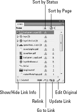
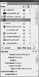
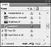
The Links palette, shown in Figure 22.32, lists all placed files in an InDesign document. It also lists the file's location in the document. You open the Links palette by choosing Window
Depending on the state of the linked file, one of the following icons may appear to the right of the file name:
Missing file: A red stop sign icon indicates that the placed file is missing. This means that the defined link is broken and that the file has been moved or renamed or is on a network or CD-ROM that can no longer be found.
Modified link: A yellow triangle icon denotes that a more up-to-date version of the placed file is available and that you need to update the link.
Embedded link: A gray square icon marks any embedded linked files within the current document.
Layer Visibility Override: This icon shows up when the Layer Visibility Override toggle is enabled for the linked file. This uses the layer visibility settings for the InDesign document instead of the native application.
You can sort the placed files listed within the Links palette by Name, Page, or Status using the commands found in the palette menu or by clicking the column heads. You also can change the column arrangement using the Panel Options dialog box.
If you want to pull all of the linked files from their various places on your hard drive to a single folder, you can use the Copy Links to command in the Links palette menu. This is a handy command if you want to bundle the entire document with all its linked files together into a single folder.
All placed files in the Links palette have links that point to the original file location. If you doubleclick on a placed file in the layout with the Option/Alt key held down, the original file opens within the application originally used to create it. You also can open a file in its original application by selecting the Edit Original palette menu command in the Links palette or by selecting an item in the Links palette and clicking the Edit Original button at the bottom of the palette. Another option is to open the selected object with another application using the Edit With option.
The Links palette also is helpful in locating files placed within InDesign. Selecting a placed file in the Links palette and choosing the Go to Link palette menu command displays the page upon which the placed file is located and selects the placed content. You also can jump to the linked content by clicking the page number shown to the right of the object in the Links panel. Alternatively, you can retrieve information by clicking the Go to Link button at the bottom of the Links palette. If a placed object is selected, then its corresponding link is highlighted in the Links palette.
If you click the Show/Hide Link Information button in the Links panel, the lower panel reveals the Link Information for the selected link. This panel, shown in Figure 22.33, shows information about the linked file including its name, the last date it was modified, size, color space, file type, and so on. It also lists the link to the original object with a Relink button.
Clicking Relink in the Link Information dialog box opens a file dialog box that points to the selected placed file. If the linked file displays the Missing Image icon, you can use this button to locate the original file and reestablish the link.
If you do not select objects in the Links palette, selecting the Relink palette menu option or clicking the Relink button at the bottom of the palette causes InDesign to scan for any missing placed files. When a missing placed file is found, a file dialog box opens, allowing you to locate the missing file. When the file is found or when you click the Skip button, the list is scanned again until all the missing files have been relinked.
Any out-of-date placed files may be manually updated using the Update Link palette menu command or by selecting the file link in the Links palette and clicking on the Update Links button at the bottom of the palette. The same tip for scanning the files in the Links palette can be used to update links. If no objects are selected, you can click the Update Link palette and InDesign will scan and present a dialog box for each file that needs to be updated.
STEPS: Relinking Placed Image Files
Open an InDesign document. Choose File
Open the Links palette. Choose Window
Relink missing files. From the palette menu, select the Relink palette menu command. InDesign scans the Links palette and presents a file dialog box, for each image file that is missing. The Links palette displays all missing files at the top of the Links palette for easy reference. Locate the missing file, and click the Open button. Repeat this step for all missing files.
To ensure that images don't end up missing, you can embed them within the InDesign document using the Embed File palette menu command from the Links palette. This action places a small gray square icon next to the image's name in the Links palette and disables the link to the original file. Any future changes made to the original image file do not update in InDesign. In addition, the InDesign file size increases to accommodate the embedded file.
Warning
Embedding images increases the file size of the InDesign document and should be used judiciously.
You unembed embedded files using the Unembed File palette menu command or by relinking the file to its original.
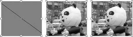
For placed images, you can set the display quality of raster images, vector images, and images that include transparency. The three display options available for placed images include Fast, Typical, and High Quality. Figure 22.35 shows an example of each of these options.
You set the Display Performance level for the selected object by choosing Object
In addition to changing the display quality for the selected object, you can also change it for the entire document. For the current view, you can select each of the following settings by choosing View
Fast: Alt+Ctrl+Shift+Z in Windows; Option+

Typical: Alt+Ctrl+Z in Windows; Option+
High Quality: Alt+Ctrl+H in Windows; Option+
The Preserve Object-Level Display Settings option causes the various display quality settings for all placed images to be remembered after the document is saved, closed, and reopened. This setting is off by default, which causes all objects to use the display settings specified in the View menu to be used when the document is opened again.
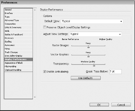
The display quality settings are configurable using the InDesign/Edit
Note
The Text Greeking preference isn't an absolute point size.
Anchored objects, which can include text frames, placed graphics, or even groups, are attached to a section of text. When the text frame moves, the anchored object moves with it. This is convenient for sidebars or inline graphics that highlight some text.
To create an anchored graphic, you need to select a text position with the Type tool, then choose File
Tip
An existing placed graphic can be anchored by cutting the graphic by choosing Edit
With the anchored graphic selected, choose Object
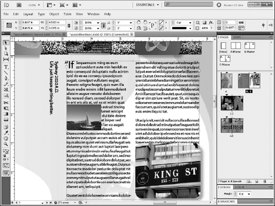
Figure 22.37. Anchored graphics are created by placing an image when a text position is selected with the Type tool.
Inline anchored objects can only be moved up or down within the text object, but custom anchored objects can be positioned anywhere in the layout. For the Inline position, you can set the Y Offset and the Above Line position lets you set the Alignment to Left, Center, Right, Towards Spine, Away from Spine, or according to the Text Alignment. You also can set the Space Before and After the anchored object. The selected anchored object can be moved manually by dragging on the object if the Prevent Manual Positioning option isn't selected.
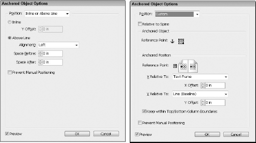
Figure 22.38. The Anchored Object Options dialog box includes different settings for setting the object's position.
If you want even more control over the position of the anchored object, you can select the Custom Position setting, which gives you many more options. Custom anchored objects can be positioned with referenced points on either side of the spine by enabling the Relative to Spine option. There are also settings for specifying the reference point for the Anchored Object and the Anchored Position. The X position can be relative and offset from the Anchor Marker, Column Edge, Text Frame, Page Margin, or Page Edge, and the Y position can be positioned relative and offset from the Baseline, Cap Height, Top of Leading, Column Edge, Text Frame, Page Margin, or Page Edge. There is also an option to Keep within Top/Bottom Column Boundaries to insure that the column layout is maintained.
In addition to graphics, you also can anchor text frames or any other frame type. Anchored text frames are created in the same way that graphic anchors are created by selecting a text location with the Type tool and choosing Object
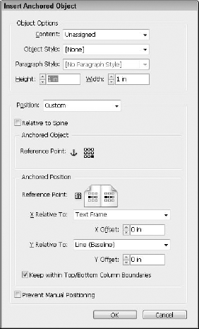
The Insert Anchored Object dialog box lets you select the object type using the Content setting, which can be Text, Graphic, or Unassigned. You also can select an Object and Paragraph Style and the object Height and Width.
To break the link between an anchored object and its text object, select the anchored object and choose Object
STEPS: Anchoring Graphics to Text
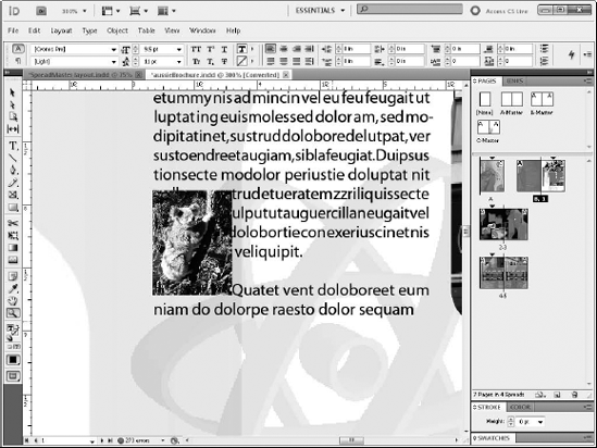
Open a layout file in InDesign. For this layout, you anchor an image of a koala to the third page.
Select the anchoring text. Click the Type tool from the Toolbox, and place the text cursor at the start of the second paragraph on the third page, which is the anchor text for the graphic.
Warning
Don't select any text in the text frame or the placed graphic replaces the selected text.
Create an Anchored Object. With a text position selected within the anchor text frame, choose File
Set the options for the Anchored Object. With the Selection tool, click the anchored graphic and choose Object
Reposition the Text Frame. With the Selection tool, select and drag the text frame to the right. Notice how the anchored graphic moves along with the text frame.
You create Layout documents using File
You use document presets to save layout settings for reuse.
You change layout settings for an existing document via the Document Setup and the Margins and Columns dialog box.
Icons of all pages and spreads are viewed from within the Pages palette.
The Pages palette helps you create Master pages, which hold objects that appear on all pages to which you apply the Master.
The Layers palette is used to place objects on different layers.
You enable Auto page numbering by adding the Auto Page Number object to a text object. When placed on a Master page, all pages based on the Master page show the page number. The document also may be divided into sections, each with a different numbering scheme.
Rulers, grids, guides, and frames are useful in establishing layouts.
You can import artwork created in Photoshop, Illustrator, and Acrobat into InDesign.
Image files placed within an InDesign document appear in the Links palette.
The Links palette may be used to relink missing image files, to update changed image files, and to locate placed images within the layout.
InDesign's Anchoring feature lets you bind images to text fields.