8.3 Source-filter Transformations
8.3.1 Vocoding or Cross-synthesis
The term vocoder has different meanings. One is “voice-coding” and refers directly to speech synthesis. Another meaning for this term is the phase vocoder, which refers to the short-time Fourier transform, as discussed in Section 7.2. The last meaning is the one of the musical instrument named the Vocoder and this is what this paragraph is about: vocoding or cross-synthesis.
This effect takes two sound inputs and generates a third one which is a combination of the two input sounds. The general idea is to combine two sounds by “spectrally shaping” the first sound by the second one and preserving the pitch of the first sound. A variant and improvement are the removal of the spectral envelope of the initial sound (also called whitening) before filtering with the spectral envelope of the second one. This implies the ability to extract a spectral envelope evolving with time and to apply it to a signal.
Although spectral estimation is well represented by its amplitude versus frequency representation, most often it is the filter representation that can be a help in the application of this spectral envelope: the channel vocoder uses the weighted sum of filtered bandpass signals, the LPC calculates an IIR filter, and even the cepstrum method can be seen as a circular convolution with an FIR filter. As this vocoding effect is very important and can give different results depending on the technique used, we will introduce these three techniques applied to the vocoding effect.
Channel Vocoder
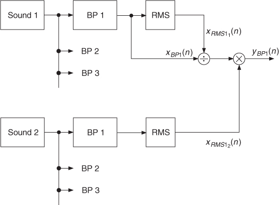
This technique uses two banks of filters provided by the channel vocoder (see Figure 8.14), as well as the RMS (root mean square) values associated with these channels. For each channel the bandpass signal is divided by the RMS value of this channel, and then multiplied by the RMS value of the other sound. The mathematical operation is given by
8.39 ![]()
where ![]() and
and ![]() represent the RMS values in channel i for the two sounds. One should be careful with the division. Of course divisions by zero should be avoided, but there should also be a threshold for avoiding the amplification of noise. This works well when sound 2 has a strong spectral envelope, for example, a voice. The division by
represent the RMS values in channel i for the two sounds. One should be careful with the division. Of course divisions by zero should be avoided, but there should also be a threshold for avoiding the amplification of noise. This works well when sound 2 has a strong spectral envelope, for example, a voice. The division by ![]() can be omitted or replaced by just modifying the amplitude of each band. Sound 1 can also be a synthetic sound (pulse, sawtooth, square).
can be omitted or replaced by just modifying the amplitude of each band. Sound 1 can also be a synthetic sound (pulse, sawtooth, square).
Figure 8.14 Basic principle of spectral mutations.
The following M-file 8.10 demonstrates a cross-synthesis between two sounds based on the channel vocoder implemented by IIR filters.
M-file 8.10 (UX_cross_synthesis_CV.m)
% UX_cross_synthesis_CV.m [DAFXbook, 2nd ed., chapter 8]
% ==== This function performs a cross-synthesis with channel vocoder
clear
%----- setting user data -----
[DAFx_in_sou,FS] = wavread(’moore_guitar’); % signal for source extraction
DAFx_in_env = wavread(’toms_diner’); % signal for spec. env. extraction
ly = min(length(DAFx_in_sou), length(DAFx_in_env)); % min signal length
DAFx_out = zeros(ly,1); % result signal
r = 0.99; % sound output normalizing ratio
lp = [1, -2*r, +r*r]; % low-pass filter used
epsi = 0.00001;
%----- init bandpass frequencies
f0 = 10; % start freq in Hz
f0 = f0/FS *2; % normalized freq
fac_third = 2∧(1/3); % freq factor for third octave
K = floor(log(1/f0) / log(fac_third)); % number of bands
%----- performing the vocoding or cross synthesis effect -----
fprintf(1, ’band number (max. %i): ’, K);
tic
for k=1:K
fprintf(1, ’%i ’, k);
f1 = f0 * fac_third; % upper freq of bandpass
[b, a] = cheby1(2, 3, [f0 f1]); % Chebyshev-type 1 filter design
f0 = f1; % start freq for next band
%-- filtering the two signals --
z_sou = filter(b, a, DAFx_in_sou);
z_env = filter(b, a, DAFx_in_env);
rms_env = sqrt(filter(1, lp, z_env.*z_env)); % RMS value of sound 2
rms_sou = sqrt(epsi+filter(1, lp, z_sou.*z_sou)); % with whitening
% rms_sou = 1.; % without whitening
DAFx_out = DAFx_out + z_sou.*rms_env./rms_sou; % add result to output buffer
end
fprintf(1, ’ ’);
toc
%----- playing and saving output sound -----
soundsc(DAFx_out, FS)
DAFx_out_norm = r * DAFx_out/max(abs(DAFx_out)); % scale for wav output
wavwrite(DAFx_out_norm, FS, ’CrossCV’)
This program performs bandpass filtering inside a loop. Precisely, Chebychev type 1 filters are used, which are IIR filters with a ripple of 3 dB in the passband. The bandwidth is chosen as one-third of an octave, hence the 0.005 to 0.0063 window relative to half of the sampling rate in MATLAB's definition. Then sound 1 and sound 2 are filtered, and the RMS value of the filtered sound 2 is extracted: z2 is squared, filtered by a two pole filter on the x axis, and its square root is taken. This RMS2 value serves as a magnitude amplifier for the z1 signal, which is the filtered version of sound 1. This operation is repeated every one-third of an octave by multiplying the frequency window, which is used for the definition of the filter, by 1.26 (3rd root of 2). A whitening process can be introduced by replacing line rms1 = 1.; with rms1 = epsi + norm(filter(1, lp, z1.*z1), 2);. A small value epsi (0.0001) is added to RMS1 to avoid division by zero. If epsi is greater, the whitening process is attenuated. Thus this value can be used as a control for whitening.
Linear Prediction
Cross-synthesis between two sounds can also be performed using the LPC method [Moo79, KAZ00]. One filter removes the spectral envelope of the first sound and the spectral envelope of the second sound is used to filter the excitation signal of the first sound, as shown in Figure 8.15.
Figure 8.15 Cross-synthesis with LPC.
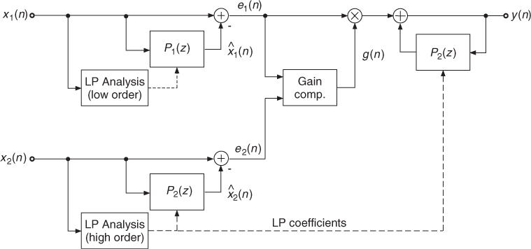
The following M-file 8.11 performs cross-synthesis based on the LPC method. The prediction coefficients of sound 1 are used for an FIR filter to whiten the original sound. The prediction coefficients of sound 2 are used in the feedback path of a synthesis filter, which performs filtering of the excitation signal of sound 1 with the spectral envelope derived from sound 2.
M-file 8.11 (UX_cross_synthesis_LPC.m)
% UX_cross_synthesis_LPC.m [DAFXbook, 2nd ed., chapter 8]
% ==== This function performs a cross-synthesis with LPC
clear;
%----- user data -----
[DAFx_in_sou, FS] = wavread(’moore_guitar.wav’); % sound 1: source/excitation
DAFx_in_env = wavread(’toms_diner.wav’); % sound 2: spectral env.
long = 400; % block length for calculation of coefficients
hopsize = 160; % hop size (is 160)
env_order = 20 % order of the LPC for source signal
source_order = 6 % order of the LPC for excitation signal
r = 0.99; % sound output normalizing ratio
%----- initializations -----
ly = min(length(DAFx_in_sou), length(DAFx_in_env));
DAFx_in_sou = [zeros(env_order, 1); DAFx_in_sou; ...
zeros(env_order-mod(ly,hopsize),1)] / max(abs(DAFx_in_sou));
DAFx_in_env = [zeros(env_order, 1); DAFx_in_env; ...
zeros(env_order-mod(ly,hopsize),1)] / max(abs(DAFx_in_env));
DAFx_out = zeros(ly,1); % result sound
exc = zeros(ly,1); % excitation sound
w = hanning(long, ’periodic’); % window
N_frames = floor((ly-env_order-long)/hopsize); % number of frames
%----- Perform ross-synthesis -----
tic
for j=1:N_frames
k = env_order + hopsize*(j-1); % offset of the buffer
%!!! IMPORTANT: function “lpc“ does not give correct results for MATLAB 6 !!!
[A_env, g_env] = calc_lpc(DAFx_in_env(k+1:k+long).*w, env_order);
[A_sou, g_sou] = calc_lpc(DAFx_in_sou(k+1:k+long).*w, source_order);
gain(j) = g_env;
ae = - A_env(2:env_order+1); % LPC coeff. of excitation
for n=1:hopsize
excitation1 = (A_sou/g_sou) * DAFx_in_sou(k+n:-1:k+n-source_order);
exc(k+n) = excitation1;
DAFx_out(k+n) = ae * DAFx_out(k+n-1:-1:k+n-env_order)+g_env*excitation1;
end
end
toc
%----- playing and saving output signal -----
DAFx_out = DAFx_out(env_order+1:length(DAFx_out)) / max(abs(DAFx_out));
soundsc(DAFx_out, FS)
DAFx_out_norm = r * DAFx_out/max(abs(DAFx_out)); % scale for wav output
wavwrite(DAFx_out_norm, FS, ’CrossLPC’)
Cepstrum
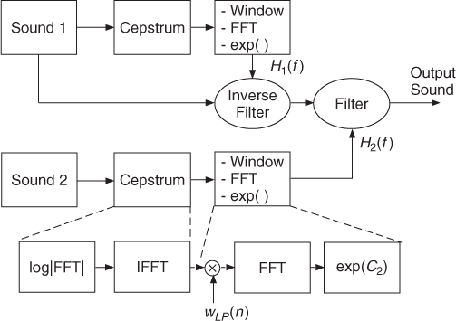
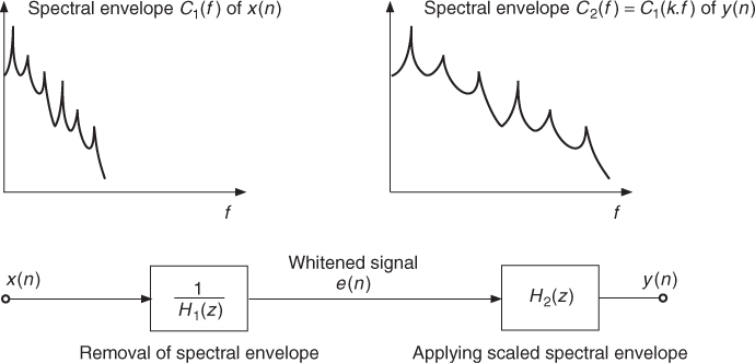
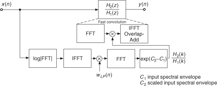
Signal processing based on cepstrum analysis is also called homomorphic signal processing [OS75, PM96]. We have seen that we can derive the spectral envelope (in dB) with the cepstrum technique. Reshaping a sound is achieved by whitening (filtering) a sound with the inverse spectral envelope 1/|H1(f)| and then filtering with the spectral envelope |H2(f)| of the second sound (see Figure 8.16). The series connection of both filters leads to a transfer function H2(f)/H1(f). By taking the logarithm according to log|H2(f)|/|H1(f)| = log|H2(f)| − log|H1(f)|, the filtering operation is based on the difference of the two spectral envelopes. The first spectral envelope performs the whitening by inverse filtering and the second spectral envelope introduces the formants. The inverse filtering of the input sound 1 and subsequent filtering with spectral envelope of sound 2 can be performed in one step by the fast convolution technique.
Figure 8.16 Basic principle of homomorphic cross-synthesis. The spectral envelopes of both sounds are derived by the cepstrum method.
Here we present the core of a program given by M-file 8.12 that uses the spectral envelope of a sound (number 2) superimposed on a sound (number 1). Though musically very effective, this first program does not do any whitening of sound 1.
M-file 8.12 (UX_cross_synthesis_cepstrum.m)
% UX_cross_synthesis_cepstrum.m [DAFXbook, 2nd ed., chapter 8]
% ==== This function performs a cross-synthesis with cepstrum
clear all; close all
%----- user data -----
% [DAFx_sou, SR] = wavread(’didge_court.wav’); % sound 1: source/excitation
% DAFx_env = wavread(’la.wav’); % sound 2: spectral enveloppe
[DAFx_sou, SR] = wavread(’moore_guitar.wav’); % sound 1: source/excitation
DAFx_env = wavread(’toms_diner.wav’); % sound 2: spectral enveloppe
s_win = 1024; % window size
n1 = 256; % step increment
order_sou = 30; % cut quefrency for sound 1
order_env = 30; % cut quefrency for sound 2
r = 0.99; % sound output normalizing ratio
%----- initialisations -----
w1 = hanning(s_win, ’periodic’); % analysis window
w2 = w1; % synthesis window
hs_win = s_win/2; % half window size
grain_sou = zeros(s_win,1); % grain for extracting source
grain_env = zeros(s_win,1); % grain for extracting spec. enveloppe
pin = 0; % start index
L = min(length(DAFx_sou),length(DAFx_env));
pend = L - s_win; % end index
DAFx_sou = [zeros(s_win, 1); DAFx_sou; ...
zeros(s_win-mod(L,n1),1)] / max(abs(DAFx_sou));
DAFx_env = [zeros(s_win, 1); DAFx_env; ...
zeros(s_win-mod(L,n1),1)] / max(abs(DAFx_env));
DAFx_out = zeros(L,1);
%----- cross synthesis -----
while pin<pend
grain_sou = DAFx_sou(pin+1:pin+s_win).* w1;
grain_env = DAFx_env(pin+1:pin+s_win).* w1;
%===========================================
f_sou = fft(grain_sou); % FT of source
f_env = fft(grain_env)/hs_win; % FT of filter
%---- computing cepstrum ----
flog = log(0.00001+abs(f_env));
cep = ifft(flog); % cepstrum of sound 2
%---- liftering cepstrum ----
cep_cut = zeros(s_win,1);
cep_cut(1:order_sou) = [cep(1)/2; cep(2:order_sou)];
flog_cut = 2*real(fft(cep_cut));
%---- computing spectral enveloppe ----
f_env_out = exp(flog_cut); % spectral shape of sound 2
grain = (real(ifft(f_sou.*f_env_out))).*w2; % resynthesis grain
% ===========================================
DAFx_out(pin+1:pin+s_win) = DAFx_out(pin+1:pin+s_win) + grain;
pin = pin + n1;
end
%----- listening and saving the output -----
% DAFx_in = DAFx_in(s_win+1:s_win+L);
DAFx_out = DAFx_out(s_win+1:length(DAFx_out)) / max(abs(DAFx_out));
soundsc(DAFx_out, SR);
DAFx_out_norm = r * DAFx_out/max(abs(DAFx_out)); % scale for wav output
wavwrite(DAFx_out_norm, SR, ’CrossCepstrum’)
In this program n1 represents the analysis step increment (or hop size), and grain_sou and grain_env windowed buffers of DAFx_in_sou and DAFx_in_env. f_sou is the FFT of grain_sou and f_env is the spectral envelope derived from the FFT of grain_env. Although this algorithm performs a circular convolution, which theoretically introduces time aliasing, the resulting sound does not have artifacts.
Whitening DAFx_in_sou before processing it with the spectral envelope of DAFx_in_env can be done in a combined step: we calculate the spectral envelope of DAFx_in_sou and subtract it (in dB) from the spectral envelope of DAFx_in_env. The following code lines given by M-file 8.13 perform a whitening of DAFx_in_sou and a cross-synthesis with DAFx_in_env.
M-file 8.13 (UX_cross_synthesis_cepstrum_whitening.m)
%===========================================
f_sou = fft(grain_sou); % FT of source
f_env = fft(grain_env)/hs_win; % FT of filter
%---- computing cepstra ----
flog_sou = log(0.00001+abs(f_sou));
cep_sou = ifft(flog_sou); % cepstrum of sound 1 / source
flog_env = log(0.00001+abs(f_env));
cep_env = ifft(flog_env); % cepstrum of sound 2 / env.
%---- liftering cepstra ----
cep_cut_env = zeros(s_win,1);
cep_cut_env(1:order_env) = [cep_env(1)/2; cep_env(2:order_env)];
flog_cut_env = 2*real(fft(cep_cut_env));
cep_cut_sou = zeros(s_win,1);
cep_cut_sou(1:order_sou) = [cep_sou(1)/2; cep_sou(2:order_sou)];
flog_cut_sou = 2*real(fft(cep_cut_sou));
%---- computing spectral enveloppe ----
f_env_out = exp(flog_cut_env - flog_cut_sou); % whitening with source
grain = (real(ifft(f_sou.*f_env_out))).*w2; % resynthesis grain
% ===========================================
In this program flog_cut_sou and flog_cut_env represent (in dB) the spectral envelopes derived from grain_sou and grain_env for a predefined cut quefrency. Recall that this value is given in samples. It should normally be below the pitch period of the sound, and the lower it is, the more smoothed the spectral envelope will be.
8.3.2 Formant Changing
This effect produces a “Donald Duck” voice without any alteration of the fundamental frequency. It can be used for performing an alteration of a sound whenever there is a formant structure. However, it can also be used in conjunction with pitch-shifted sounds for recovering a natural formant structure (see Section 8.3.4).
The musical goal is to remove the spectral envelope from one sound and to impose another one, which is a warped version of the first one, as shown in Figure 8.17, where the signal processing is also illustrated. This means that we have to use a spectral correction that is a ratio of the two spectral envelopes. In this way the formants, if there are any, are changed according to this warping function. For example, a transposition of the spectral envelope by a factor of two will give a “Donald Duck” effect without time stretching. This effect can also be seen as a particular case of cross-synthesis, where the modifier comes from an interpolated version of the original sound. Though transposition of the spectral envelope is classical, other warping functions can be used.
Figure 8.17 Formant changing by frequency scaling the spectral envelope and time-domain processing.
From a signal-processing point of view the spectral correction for formant changing can be seen in the frequency domain as H2(f)/H1(f). First divide by the spectral envelope H1(f) of the input sound and then multiply by the frequency scaled spectral envelope H2(f). In the cepstrum domain the operation H2(f)/H1(f) leads to the subtraction C2(f) − C1(f), where C(f) = log|H(f)|. When using filters for time-domain processing, the transfer function is H2(f)/H1(f) (see Figure 8.17). We will shortly describe three different methods for the estimation of the two spectral envelopes.
Interpolation of the Input Signal
The spectral envelopes C1(f) and C2(f), or filters H1(f) and H2(f) can be obtained by different techniques. If C2(f) is a frequency-scaled version of C1(f), one can calculate the spectral envelope C2(f) from the analysis of a transposed version of the initial signal, as shown in Figure 8.18. The transposed version is obtained by time-domain interpolation of the input signal. The channel vocoder, LPC and the cepstrum method, allow the estimation of either the spectral envelope or the corresponding filter. One must take care to keep synchronicity between the two signals. This can be achieved by changing the hop size according to this ratio. The algorithm works as follows:
- Whitening: filter the input signal with frequency response
 or subtract the input spectral envelope C1(f) = log|H1(f)| from the log of the input magnitude spectrum.
 - The filter H1(f) or the spectral envelope C1(f) is estimated from the input signal.
- Formant changing: apply the filter with frequency response H2(f) to the whitened signal or add the spectral envelope C2(f) = log|H2(f)| to the whitened log of the input magnitude spectrum.
- The filter H2(f) or the spectral envelope C2(f) is estimated from the interpolated input signal.
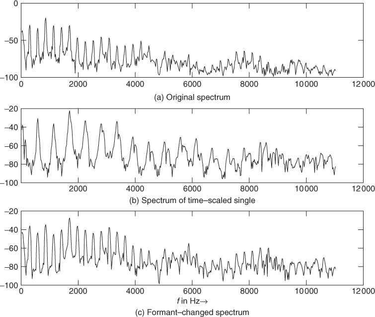
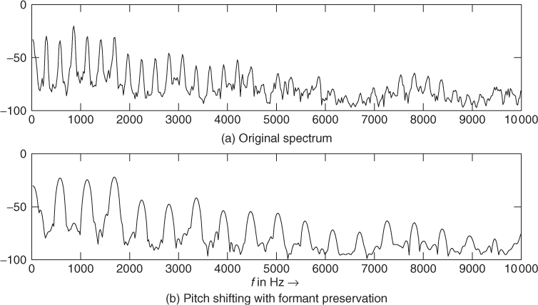
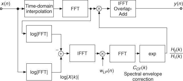
Formant changing based on the cepstrum analysis is shown in Figure 8.19. The spectral correction is calculated from the difference of the log values of the FFTs, of both the input signal and the interpolated input signal. This log difference is transformed to the cepstrum domain, lowpass weighted and transformed back by the exponential to the frequency domain. Then, the filtering of the input signal with the spectral correction filter H2(z)/H1(z) is performed in the frequency domain. This fast convolution is achieved by multiplication of the corresponding Fourier transforms of the input signal and the spectral correction filter. The result is transformed back to the time domain by an IFFT yielding the output signal. An illustrative example is shown in Figure 8.20. The M-file 8.14 demonstrates this technique.
Figure 8.18 Formant changing by time-domain processing.
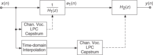
Figure 8.19 Formant changing by frequency-domain processing: cepstrum analysis, spectral correction filter computation and fast convolution.
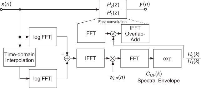
Figure 8.20 Example of formant changing: the upper plot shows the input spectrum and the middle plot the spectrum of the interpolated signal. The lower plot shows the result of the formant-changing operation, where the spectral envelope of the interpolated spectrum can be noticed.
M-file 8.14 (UX_fmove_cepstrum.m)
% UX_fmove_cepstrum.m [DAFXbook, 2nd ed., chapter 8]
% ==== This function performs a formant warping with cepstrum
clear; clf;
%----- user data -----
fig_plot = 0; % use any value except 0 or [] to plot figures
[DAFx_in, SR] = wavread(’la.wav’); % sound file
warping_coef = 2.0;
n1 = 512; % analysis hop size
n2 = n1; % synthesis hop size
s_win = 2048; % window length
order = 50; % cut quefrency
r = 0.99; % sound output normalizing ratio
%----- initializations -----
w1 = hanning(s_win, ’periodic’); % analysis window
w2 = w1; % synthesis window
hs_win = s_win/2; % half window size
L = length(DAFx_in); % signal length
DAFx_in = [zeros(s_win, 1); DAFx_in; ...
zeros(s_win-mod(L,n1),1)] / max(abs(DAFx_in)); % 0-pad + normalize
DAFx_out = zeros(L,1); % output signal
t = 1 + floor((0:s_win-1)*warping_coef); % apply the warping
lmax = max(s_win,t(s_win));
tic
%UUUUUUUUUUUUUUUUUUUUUUUUUUUUUUUUUUUUUUU
pin = 0;
pout = 0;
pend = L - s_win;
if(fig_plot)
pin = 6500;
pend = pin + s_win;
end
while pin<pend
grain = DAFx_in(pin+1:pin+s_win).* w1;
%===========================================
f = fft(grain)/hs_win; % spectrum of grain
flogs = 20*log10(0.00001+abs(f)); % log|X(k)|
grain1 = DAFx_in(pin+t).* w1; % linear interpolation of grain
f1 = fft(grain1)/hs_win; % spectrum of interpolated grain
flogs1 = 20*log10(0.00001 + abs(f1)); % log|X1(k)|
flog = log(0.00001+abs(f1)) - log(0.00001+abs(f));
cep = ifft(flog); % cepstrum
cep_cut = [cep(1)/2; cep(2:order); zeros(s_win-order,1)];
corr = exp(2*real(fft(cep_cut))); % spectral shape
grain = (real(ifft(f.*corr))).*w2;
fout = fft(grain);
flogs2 = 20*log10(0.00001+abs(fout));
%----- figures for real-time spectral shape up to SR/2 -----
if(fig_plot)
range = (1:hs_win/2);
subplot(3,1,1); plot((range)*SR/s_win, flogs(range));
title(’a) original spectrum’); drawnow;
subplot(3,1,2); plot((range)*SR/s_win, flogs1(range));
title(’b) spectrum of time-scaled signal’);
subplot(3,1,3); plot((range)*SR/s_win, flogs2(range));
title(’c) formant changed spectrum’);
xlabel(’f in Hz ightarrow’);
drawnow
end
% ===========================================
DAFx_out(pout+1:pout+s_win) = DAFx_out(pout+1:pout+s_win) + grain;
pin = pin + n1;
pout = pout + n2;
end
%UUUUUUUUUUUUUUUUUUUUUUUUUUUUUUUUUUUUUUU
toc
%----- listening and saving the output -----
soundsc(DAFx_out, SR);
DAFx_out_norm = r * DAFx_out/max(abs(DAFx_out)); % scale for wav output
wavwrite(DAFx_out_norm, SR, ’la_fmove.wav’);
Interpolation or Scaling of the Spectral Envelope
The direct warping is also possible, for example, by using the interpolation of the spectral envelope derived from a cepstrum technique: C2(f) = C1(k · f) or C2(f/k) = C1(f). There are, however, numerical limits: the cepstrum method uses an FFT and frequencies should be below half of the sampling frequency. Thus, if the transposition factor is greater than one, we will get only a part of the initial envelope. If the transposition factor is less than one, we will have to zero-pad the rest of the spectral envelope to go up to half of the sampling frequency. The block diagram for the algorithm using the cepstrum analysis method is shown in Figure 8.21. The following M-file 8.15 demonstrates this method.
M-file 8.15 (UX_fomove_cepstrum.m)
% UX_fomove_cepstrum.m [DAFXbook, 2nd ed., chapter 8]
% ==== This function performs a formant warping with cepstrum
clear; clf;
%----- user data -----
fig_plot = 0; % use any value except 0 or [] to plot figures
[DAFx_in, SR] = wavread(’la.wav’); % sound file
warping_coef = 2.0
n1 = 512; % analysis hop size
n2 = n1; % synthesis hop size
s_win = 2048; % window length
order = 50; % cut quefrency
r = 0.99; % sound output normalizing ratio
%----- initializations -----
w1 = hanning(s_win, ’periodic’); % analysis window
w2 = w1; % synthesis window
hs_win = s_win/2; % half window size
L = length(DAFx_in); % signal length
DAFx_in = [zeros(s_win, 1); DAFx_in; ...
zeros(s_win-mod(L,n1),1)] / max(abs(DAFx_in)); % 0-pad + normalize
DAFx_out = zeros(L,1);
x0 = floor(min((1+(0:hs_win)/warping_coef), 1+hs_win));
% apply the warping
x = [x0, x0(hs_win:-1:2)];% symmetric extension
tic
%UUUUUUUUUUUUUUUUUUUUUUUUUUUUUUUUUUUUUUU
pin = 0;
pout = 0;
pend = L - s_win;
while pin<pend
grain = DAFx_in(pin+1:pin+s_win).* w1;
%===========================================
f = fft(grain)/hs_win;
flog = log(0.00001+abs(f));
cep = ifft(flog);
cep_cut = [cep(1)/2; cep(2:order); zeros(s_win-order,1)];
%---- flog_cut1|2 = spectral shapes before/after formant move
flog_cut1 = 2*real(fft(cep_cut));
flog_cut2 = flog_cut1(x);
corr = exp(flog_cut2-flog_cut1);
grain = (real(ifft(f.*corr))).*w2;
% ===========================================
DAFx_out(pout+1:pout+s_win) = DAFx_out(pout+1:pout+s_win) + grain;
pin = pin + n1;
pout = pout + n2;
end
%UUUUUUUUUUUUUUUUUUUUUUUUUUUUUUUUUUUUUUU
toc
%----- listening and saving the output -----
soundsc(DAFx_out, SR);
DAFx_out_norm = r * DAFx_out/max(abs(DAFx_out)); % scale for wav output
wavwrite(DAFx_out_norm, SR, ’la_fomove.wav’);
Figure 8.21 Formant changing by scaling the spectral envelope.
Direct Warping of Filters
A direct warping of the spectral envelope filter H1(z) to H2(z) is also possible. The warping of a filter transfer function can be performed by the allpass function ![]() . Substituting z−1 in the transfer function H1(z) by
. Substituting z−1 in the transfer function H1(z) by ![]() yields the warped transfer function H2(z). Further details on warping can be found in Chapter 11 and in [Str80, LS81, HKS+00].
yields the warped transfer function H2(z). Further details on warping can be found in Chapter 11 and in [Str80, LS81, HKS+00].
8.3.3 Spectral Interpolation
Spectral interpolation means that instead of mixing two sounds, we mix their excitation signals independently of their spectral envelopes, as shown in Figure 8.22. If we have the decomposition of sound grains in the frequency domain according to E(f) · H(f), where E(f) represents the Fourier transform of the excitation and H(f) is the spectral envelope (H(f) = exp[C(f)]), we can perform spectral interpolation between two sounds by mixing according to
8.40 ![]()
The excitation grains and the spectral envelopes are added. This transformed representation is then used for the resynthesis operation. We introduce cross-terms by this method, which musically means that the excitation source of one sound also influences the spectral envelope of the second and conversely. For regular mixing of two sounds the result would be k1E1(f) · H1(f) + k2E2(f) · H2(f). The M-file 8.16 performs time-varying spectral interpolation between two sounds. We go from a first sound to another one by independently mixing the sources and resonances of these two sounds.
M-file 8.16 (UX_spectral_interp.m)
% UX_spectral_interp.m [DAFXbook, 2nd ed., chapter 8]
% ==== This function performs a spectral interpolation with cepstrum
%
% k: spectral mix, calculated at every step in this example, as
% starts with gain=0 for sound 1 and gain=1 for sound 2
% finishes with gain=1 for sound 1 and gain=0 for sound 2
% so we move from sound 1 to sound 2
clear;
%----- user data -----
[DAFx_in1,SR] = wavread(’claire_oubli_voix.WAV’); % sound 1
DAFx_in2 = wavread(’claire_oubli_flute.WAV’); % sound 2
n1 = 512; % analysis hop size
n2 = n1; % synthesis hop size
s_win = 2048; % window length
w1 = hanning(s_win, ’periodic’); % analysis window
w2 = w1; % synthesis window
cut = 50 % cut-off quefrency
%----- initializations -----
L = min(length(DAFx_in1), length(DAFx_in2));
DAFx_in1 = [zeros(s_win, 1); DAFx_in1; ...
zeros(s_win-mod(L,n1),1)] / max(abs(DAFx_in1)); % 0-pad + norm
DAFx_in2 = [zeros(s_win, 1); DAFx_in2; ...
zeros(s_win-mod(L,n1),1)] / max(abs(DAFx_in2)); % 0-pad + norm
DAFx_out = zeros(length(DAFx_in1),1);
tic
%UUUUUUUUUUUUUUUUUUUUUUUUUUUUUUUUUUUUUUU
pin = 0;
pout = 0;
pend = L - s_win;
while pin<pend
%---- k factor (spectral mix) wich varies between 0 and 1
k = pin / pend;
kp = 1 - k;
%---- extracting input grains
grain1 = DAFx_in1(pin+1:pin+s_win) .* w1;
grain2 = DAFx_in2(pin+1:pin+s_win) .* w1;
%===========================================
%---- computing spectral shape of sound 1
f1 = fft(fftshift(grain1));
flog = log(0.00001+abs(f1));
cep = fft(flog);
cep_coupe = [cep(1)/2; cep(2:cut); zeros(s_win-cut,1)];
flog_coupe1 = 2*real(ifft(cep_coupe));
spec1 = exp(flog_coupe1);
%---- computing spectral shape of sound 2
f2 = fft(fftshift(grain2));
flog = log(0.00001+abs(f2));
cep = fft(flog);
cep_coupe = [cep(1)/2; cep(2:cut); zeros(s_win-cut,1)];
flog_coupe2 = 2*real(ifft(cep_coupe));
spec2 = exp(flog_coupe2);
%----- interpolating the spectral shapes in dBs
spec = exp(kp*flog_coupe1+k*flog_coupe2);
%----- computing the output spectrum and grain
ft = (kp*f1./spec1+k*f2./spec2).*spec;
grain = fftshift(real(ifft(ft))).*w2;
%===========================================
DAFx_out(pout+1:pout+s_win) = DAFx_out(pout+1:pout+s_win) + grain;
pin = pin + n1;
pout = pout + n2;
end
%UUUUUUUUUUUUUUUUUUUUUUUUUUUUUUUUUUUUUUU
toc
%----- listening and saving the output -----
% DAFx_in = DAFx_in1(s_win+1:s_win+L);
DAFx_out = DAFx_out(s_win+1:s_win+L) / max(abs(DAFx_out));
soundsc(DAFx_out, SR);
wavwrite(DAFx_out, SR, ’spec_interp.wav’);
Figure 8.22 A possible implementation of spectral interpolation between two sounds.
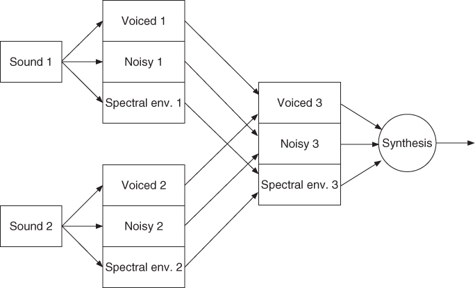
Spectral interpolation is the first step towards morphing, a term borrowed from the visual domain but with a much more ambiguous meaning in the audio domain. Time synchronization between the two sounds has to be taken into account. The matter of pitch interpolation should be different from the mixing of excitation signals as it is presented here. Morphing usually relies on high-level attributes and spectral interpolation and follows more complicated schemes, such as shown in Figure 8.22. Advanced methods will be discussed in Chapter 10.
8.3.4 Pitch Shifting with Formant Preservation
In Chapter 6, we saw some pitch-shifting algorithms which transpose the entire spectrum, and consequently the spectral envelope. This typically alters the voice giving a “Donald Duck” or “barrel” feeling. For pitch shifting a sound without changing its articulation, i.e., its formant structure, one has to keep the spectral envelope of the original sound.
Inverse Formant Move Plus Pitch Shifting
A possible way to remove the artifacts is to perform a formant move in the inverse direction of the pitch shifting. This process can be inserted into a FFT/IFFT-based pitch-shifting algorithm before the reconstruction, as shown in Figure 8.23. For this purpose we have to calculate a correction function for this formant move.
Figure 8.23 Pitch shifting with formant preservation: the pitch shifting is performed in the frequency domain.

The following algorithm (see M-file 8.17) is based on the pitch-shifting algorithm described in Chapter 7 (see Section 7.4.4). The only modification is a formant move calculation before the reconstruction of every individual grain, which will be overlapped and added. For the formant move calculation, a crude interpolation of the analysis grain is performed, in order to recover two spectral envelopes: the one of the original grain and the one of its pitch-transposed version. From these two spectral envelopes the correction factor is computed (see previous section) and applied to the magnitude spectrum of the input signal before the reconstruction of the output grain (see Figure 8.23).
M-file 8.17 (UX_pitch_pv_move.m)
% UX_pitch_pv_move.m [DAFXbook, 2nd ed., chapter 7]
% ==== This function performs a ptch-shifting that preserves
% the spectral enveloppe
clear;
%----- user data -----
[DAFx_in, SR] = wavread(’la.wav’); % sound file
n1 = 512; % analysis hop size
% try n1=400 (pitch down) or 150 (pitch up)
n2 = 256; % synthesis hop size
% keep it a divisor of s_win (256 is pretty good)
s_win = 2048; % window length
order = 50; % cut quefrency
coef = 0.99; % sound output normalizing ratio
%----- initializations -----
w1 = hanning(s_win, ’periodic’); % analysis window
w2 = w1; % synthesis window
tscal = n2/n1; % time-scaling ratio
s_win2 = s_win/2;
L = length(DAFx_in);
DAFx_in = [zeros(s_win, 1); DAFx_in; ...
zeros(s_win-mod(L,n1),1)] / max(abs(DAFx_in)); % 0-pad + norm
%-- for phase unwrapping
omega = 2*pi*n1*[0:s_win-1]'/s_win;
phi0 = zeros(s_win,1);
psi = zeros(s_win,1);
%-- for linear interpolation of a grain of length s_win
lx = floor(s_win*n1/n2);
DAFx_out = zeros(lx+length(DAFx_in),1);
x = 1 + (0:lx-1)'*s_win/lx;
ix = floor(x);
ix1 = ix + 1;
dx = x - ix;
dx1 = 1 - dx;
warp = n1/n2 % warpinf coefficient, = 1/tscal
t = 1 + floor((0:s_win-1)*warp);
lmax = max(s_win,t(s_win))
tic
%UUUUUUUUUUUUUUUUUUUUUUUUUUUUUUUUUUUUUUU
pin = 0;
pout = 0;
pend = L - lmax;
while pin<pend
grain = DAFx_in(pin+1:pin+s_win).* w1;
%===========================================
f = fft(fftshift(grain));
r = abs(f);
phi = angle(f);
%---- unwrapping the phase ----
delta_phi = omega + princarg(phi-phi0-omega);
phi0 = phi;
psi = princarg(psi+delta_phi*tscal);
%---- moving formant ----
grain1 = DAFx_in(pin+t) .* w1;
f1 = fft(grain1)/s_win2;
flog = log(0.00001+abs(f1))-log(0.00001+abs(f));
cep = ifft(flog);
cep_cut = [cep(1)/2; cep(2:order); zeros(s_win-order,1)];
corr = exp(2*real(fft(cep_cut))); % correction enveloppe
%---- spec env modif.: computing output FT and grain ----
ft = (r.* corr.* exp(i*psi));
grain = fftshift(real(ifft(ft))).*w2;
%---- pitch-shifting: interpolating output grain -----
grain2 = [grain;0];
grain3 = grain2(ix).*dx1+grain2(ix1).*dx;
% plot(grain);drawnow;
%===========================================
DAFx_out(pout+1:pout+lx) = DAFx_out(pout+1:pout+lx) + grain3;
pin = pin + n1;
pout = pout + n1;
end
%UUUUUUUUUUUUUUUUUUUUUUUUUUUUUUUUUUUUUUU
toc
%----- listening and saving the output -----
% DAFx_in = DAFx_in(s_win+1:s_win+L);
DAFx_out = coef * DAFx_out(s_win+1:s_win+L) / max(abs(DAFx_out));
soundsc(DAFx_out, SR);
wavwrite(DAFx_out, SR, ’la_pitch_pv_move.wav’);
An illustrative example of pitch shifting with formant preservation is shown in Figure 8.24. The spectral envelope is preserved and the pitch is increased by a factor of two.
Figure 8.24 Example of pitch shifting with formant preservation.
Resampling Plus Formant Move
It is also possible to combine an interpolation scheme with a formant move inside an analysis-synthesis loop. The block diagram in Figure 8.25 demonstrates this approach. The input segments are interpolated from length N1 to length N2. This interpolation or resampling also changes the time duration and thus performs pitch shifting in the time domain. The resampled segment is then applied to an FFT/IFFT-based analysis/synthesis system, where the correction function for the formant move is computed by the cepstrum method. This correction function is based on the input spectrum and the spectrum of the interpolated signal and is computed with the help of the cepstrum technique. Then the correction function is applied to the interpolated input spectrum by the fast convolution technique.
Figure 8.25 Pitch shifting with formant preservation: the pitch shifting is performed in the time domain.
The following M-file 8.18 performs interpolation of successive grains with a ratio given by the two numbers Ra = n1 and Rs = n2 and performs a formant move to recover the original spectral envelope.
M-file 8.18 (UX_interp_move.m)
% UX_interp_move.m [DAFXbook, 2nd ed., chapter 8]
% ==== This function performs a ptch-shifting that preserves
% the spectral enveloppe
clear;
%----- user data -----
[DAFx_in, SR] = wavread(’la.wav’); % sound file
n1 = 400; % analysis hop size
% try n1=400 (pitch down) or 150 (pitch up)
n2 = 256; % synthesis hop size
% keep it a divisor of s_win (256 is pretty good)
s_win = 2048; % window length
order = 50; % cut quefrency
coef = 0.99; % sound output normalizing ratio
%----- initializations -----
w1 = hanning(s_win, ’periodic’); % analysis window
w2 = w1; % synthesis window
tscal = n2/n1 % time-scaling ratio
hs_win = s_win/2; % half window size
L = length(DAFx_in);
DAFx_in = [zeros(s_win, 1); DAFx_in; ...
zeros(s_win-mod(L,n1),1)] / max(abs(DAFx_in)); % 0-pad + norm
%-- for linear interpolation of a grain of length s_win
lx = floor(s_win*n1/n2);
DAFx_out = zeros(ceil(tscal*length(DAFx_in)),1);
x = 1 + (0:s_win-1)'*lx/s_win;
ix = floor(x);
ix1 = ix + 1;
dx = x - ix;
dx1 = 1 - dx;
warp = n1/n2 % warpinf coefficient, = 1/tscal
lmax = max(s_win,lx)
tic
%UUUUUUUUUUUUUUUUUUUUUUUUUUUUUUUUUUUUUUU
pin = 0;
pout = 0;
pend = L - lmax;
while pin<pend
%===========================================
%----- FT of interpolated grain
grain1 = (DAFx_in(pin+ix).*dx1 + DAFx_in(pin+ix1).*dx).* w1;
f1 = fft(grain1)/hs_win;
%----- FT of reference grain, for formant matching
grain2 = DAFx_in(pin+1:pin+s_win).* w1;
f2 = fft(grain2)/hs_win;
%----- correction factor for spectral enveloppe
flog = log(0.00001+abs(f2))-log(0.00001+abs(f1));
cep = ifft(flog);
cep_cut = [cep(1)/2; cep(2:order); zeros(s_win-order,1)];
corr = exp(2*real(fft(cep_cut)));
%----- so now make the formant move
grain = fftshift(real(ifft(f1.*corr))).*w2;
% plot(grain);drawnow;
%===========================================
DAFx_out(pout+1:pout+s_win) = DAFx_out(pout+1:pout+s_win) + grain;
pin = pin + n1;
pout = pout + n2;
end
%UUUUUUUUUUUUUUUUUUUUUUUUUUUUUUUUUUUUUUU
toc
%----- listening and saving the output -----
% DAFx_in = DAFx_in(s_win+1:s_win+L);
DAFx_out = coef * DAFx_out(s_win+1:length(DAFx_out)) / max(abs(DAFx_out));
soundsc(DAFx_out, SR);
wavwrite(DAFx_out, SR, ’la_interp_move.wav’);
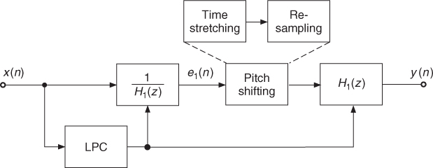
Resampling of the Excitation Signal
Instead of moving the formants, an alternative technique is to calculate an excitation signal by removing the spectral envelope, to process the excitation signal by a pitch shifting algorithm and to filter the pitch shifted excitation signal with the original spectral envelope. LPC algorithms can be used for this approach. Figure 8.26 shows a block diagram of pitch shifting with formant preservation using the LPC method. First, a predictor is computed and the predictor is used for the inverse filtering of the input signal, which yields the excitation signal. Then the excitation signal is applied to a pitch shifting algorithm and the output signal is filtered with the synthesis filter H1(z). The processing steps can be performed completely in the time domain. The pitch shifting is achieved by first time stretching and subsequent resampling.
Figure 8.26 Pitch shifting with formant preservation with the LPC method.