
Chapter 8. Understanding user requirements
The Chemical Tracking System (CTS) project was holding its first requirements elicitation workshop to learn what chemists would need to do with the system. The participants included a business analyst, Lori; the product champion for the chemists, Tim; two other chemist representatives, Sandy and Peter; and the lead developer, Ravi.
“Tim, Sandy, and Peter have identified 14 use cases that chemists would need to perform using the Chemical Tracking System,” Lori told the group. “You said the use case called ‘Request a Chemical’ is top priority and Tim already wrote a brief description for it, so let’s begin there. Tim, how do you visualize the process to request a chemical with the system?”
“First,” said Tim, “you should know that only people who have been authorized by their lab managers are allowed to request chemicals.”
“Okay, that sounds like a business rule,” Lori replied. “I’ll start a list of business rules because we’ll probably find others. It looks like we’ll have to verify that the user is on the approved list.” Lori then guided the group through a discussion of how they envisioned creating a request for a new chemical. She used flipcharts and sticky notes to collect information about preconditions, postconditions, and the interactions between the user and the system. Lori asked how a session would be different if the user were requesting a chemical from a vendor rather than from the stockroom. She asked what could go wrong and how the system should handle each error condition. After about 30 minutes, the group had a solid handle on how a user would request a chemical. They moved on to the next use case.
A necessary prerequisite to designing software that meets user needs is to understand what the users intend to do with it. Some teams take a product-centric approach. They focus on defining the features to implement in the software, with the hope that those features will appeal to prospective customers. In most cases, though, you’re better off taking a user-centric and usage-centric approach to requirements elicitation. Focusing on users and their anticipated usage helps reveal the necessary functionality, avoids implementing features that no one will use, and assists with prioritization.
User requirements are found in the second level of requirements that you saw in Figure 1-1 in Chapter 1. They lie between the business requirements that set the objectives for the project and the functional requirements that describe what developers must implement. This chapter addresses two of the most commonly employed techniques for exploring user requirements: use cases and user stories.
Analysts have long employed usage scenarios to elicit user requirements ([ref004]). The usage-centered perspective was formalized into the use case approach to requirements modeling ([ref126]; [ref041]; [ref146]). More recently, proponents of agile development introduced the concept of a “user story,” a concise statement that articulates a user need and serves as a starting point for conversations to flesh out the details ([ref043]).
Both use cases and user stories shift from the product-centric perspective of requirements elicitation to discussing what users need to accomplish, in contrast to asking users what they want the system to do. The intent of this approach is to describe tasks that users will need to perform with the system, or user-system interactions that will result in a valuable outcome for some stakeholder. That understanding leads the BA to derive the necessary functionality that must be implemented to enable those usage scenarios. It also leads to tests to verify whether the functionality was implemented correctly. Usage-centric elicitation strategies will bring you closer to understanding the user’s requirements on many classes of projects than any other technique we have used.
Use cases and user stories work well for exploring the requirements for business applications, websites, kiosks, and systems that let a user control a piece of hardware. However, they are inadequate for understanding the requirements of certain types of applications. Applications such as batch processes, computationally intensive systems, business analytics, and data warehousing might have just a few use cases. The complexity of these applications lies in the computations performed, the data found and compiled, or the reports generated, not in the user-system interactions.
Nor are use cases and user stories sufficient for specifying many embedded and other real-time systems. Consider an automated car wash. The driver of the car has just one goal—to wash the car—with perhaps a few options: underbody spray, sealer wax, polish. However, the car wash has a lot going on. It has a drive mechanism to move your car; numerous motors, pumps, valves, switches, dials, and lights; and timers or sensors to control the activation of these physical components. You also have to worry about diagnostic functionality, such as notifying the operator when a tank of liquid is nearly empty, as well as fault detection and safety requirements. What happens if the drive mechanism fails while a car is in the tunnel, or if the motor on a blower fails? A requirements technique often used for real-time systems is to list the external events to which the system must react and the corresponding system responses. See Chapter 12 for more about event analysis.
Use cases and user stories
A use case describes a sequence of interactions between a system and an external actor that results in the actor being able to achieve some outcome of value. The names of use cases are always written in the form of a verb followed by an object. Select strong, descriptive names to make it evident from the name that the use case will deliver something valuable for some user. Table 8-1 lists some sample use cases from a variety of applications.
Sample use case | |
Chemical tracking system | Request a Chemical Print Material Safety Data Sheet Change a Chemical Request Check Status of an Order Generate Quarterly Chemical-Usage Reports |
Airport check-in kiosk | Check in for a Flight Print Boarding Passes Change Seats Check Luggage Purchase an Upgrade |
Accounting system | Create an Invoice Reconcile an Account Statement Enter a Credit Card Transaction Print Tax Forms for Vendors Search for a Specific Transaction |
Online bookstore | Update Customer Profile Search for an Item Buy an Item Track a Shipped Package Cancel an Unshipped Order |
As used on agile development projects, a user story is a “short, simple description of a feature told from the perspective of the person who desires the new capability, usually a user or customer of the system” ([ref045]). User stories often are written according to the following template, although other styles also are used:
As a <type of user>, I want <some goal> so that <some reason>.
Using this template provides an advantage over the even shorter use case name because, although they both state the user’s goal, the user story also identifies the user class and the rationale behind the request for that system capability. These are valuable additions. The user class—which need not be a human being—in a user story corresponds to the primary actor in a use case (described later in this chapter). The rationale could be provided in the brief description of the use case. Table 8-2 shows how we could state some of the use cases from Table 8-2 in the form of user stories.
Application | Sample use case | Corresponding user story |
Chemical tracking system | Request a Chemical | As a chemist, I want to request a chemical so that I can perform experiments. |
Airport check-in kiosk | Check in for a Flight | As a traveler, I want to check in for a flight so that I can fly to my destination. |
Accounting system | Create an Invoice | As a small business owner, I want to create an invoice so that I can bill a customer. |
Online bookstore | Update Customer Profile | As a customer, I want to update my customer profile so that future purchases are billed to a new credit card number. |
At this level, use cases look much like user stories. Both are focused on understanding what different types of users need to accomplish through interactions with a software system. However, the two processes move in different directions from these similar starting points, as illustrated in Figure 8-1. Both approaches can also produce other deliverables, such as visual analysis models, but Figure 8-1 illustrates the core distinction.
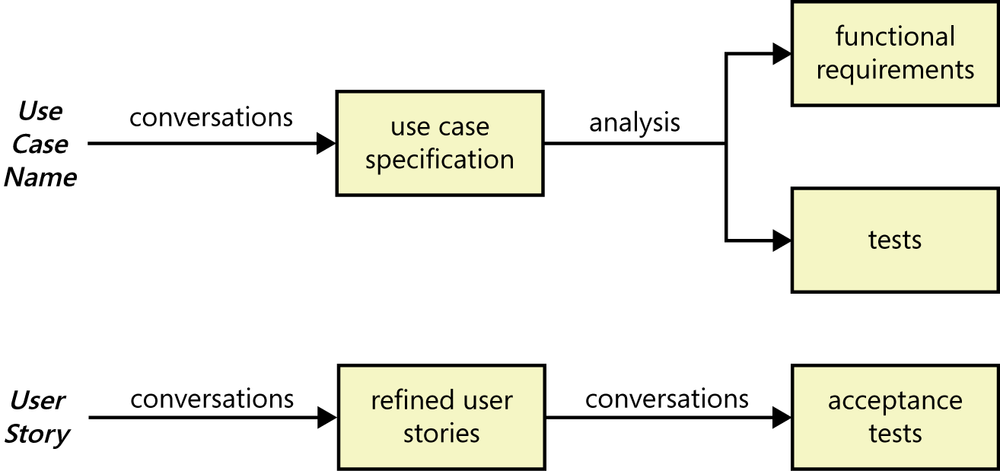
With use cases, the next step is for the BA to work with user representatives to understand how they imagine a dialog taking place with the system to perform the use case. The BA structures the information collected according to a use case template; you’ll see an example later in the chapter. The template contains numerous spaces in which to store information that can provide a rich understanding of the use case, its variants, and related information. It’s not necessary to fully complete the template if the developers can get the information they need from a briefer specification, but referring to the template during elicitation will help the participants discover all the pertinent information. From the use case specification, the BA can derive the functional requirements that developers must implement, and a tester can identify tests to judge whether the use case was properly implemented. Developers might implement an entire use case in a single release or iteration. Alternatively, they might implement just a portion of a particular use case initially, either for size or priority reasons, and then implement additional parts in future releases.
As employed on agile projects, a user story serves as a placeholder for future conversations that need to take place on a just-in-time basis among developers, customer representatives, and a business analyst (if one is working on the project). Those conversations reveal the additional information that developers must know to be able to implement the story. Refining the user stories through conversations leads to a collection of smaller, focused stories that describe individual chunks of system functionality. User stories that are too large to implement in one agile development iteration (called epics) are split into smaller stories that can be implemented within a single iteration. See Chapter 20 for more about epics and user stories.
Rather than specifying functional requirements, agile teams typically elaborate a refined user story into a set of acceptance tests that collectively describe the story’s “conditions of satisfaction.” Thinking about tests at this early stage is an excellent idea for all projects, regardless of their development approach. Test thinking helps you identify variations of the basic user story (or use case), exception conditions that must be handled, and nonfunctional requirements such as performance and security considerations. If the developer implements the necessary code to satisfy the acceptance tests—and hence to meet conditions of satisfaction—the user story is considered to be correctly implemented.
User stories provide a concise statement of a user’s needs. Use cases dive further into describing how the user imagines interacting with the system to accomplish his objective. The use case should not get into design specifics, just into the user’s mental image about the interaction. User stories offer the advantage of simplicity and conciseness, but there is a tradeoff. Use cases provide project participants with a structure and context that a collection of user stories lacks. They provide an organized way for the BA to lead elicitation discussions beyond simply collecting a list of things that users need to achieve with the system as a starting point for planning and discussion.
Not everyone is convinced that user stories are an adequate requirements solution for large or more demanding projects ([ref087]). You can examine each element of a use case (flows, preconditions, postconditions, and so on) to look for pertinent functional and nonfunctional requirements and to derive tests. This helps you avoid overlooking any requirements that developers must implement to let users perform the use case. But user stories do not replicate that structure and rigor, so it’s easier for the team to miss some acceptance tests. A BA or developer must have experience in effective user story development to avoid overlooking relevant functionality. A use-case analysis might reveal that several use cases involve similar exceptions (or other commonalities) that could perhaps be implemented as a single consistent error-handling strategy within the application. Such commonalities are more difficult to discern with a collection of user stories.
For more information about how to elicit and apply user stories when exploring user requirements, see [ref043], [ref045], or [ref157]. The rest of this chapter will focus on the use case technique, pointing out similarities and contrasts with the user story approach where appropriate.
The use case approach
As mentioned earlier, a use case describes a sequence of interactions between a system and an external actor that results in some outcome that provides value to the actor. An actor is a person (or sometimes another software system or a hardware device) that interacts with the system to perform a use case. For example, the Chemical Tracking System’s “Request a Chemical” use case involves an actor named Requester. There is no CTS user class named Requester. Both chemists and members of the chemical stockroom staff may request chemicals, so members of either user class may perform the Requester role. Following are some questions you might ask to help user representatives identify actors:
Who (or what) is notified when something occurs within the system?
Who (or what) provides information or services to the system?
Who (or what) helps the system respond to and complete a task?
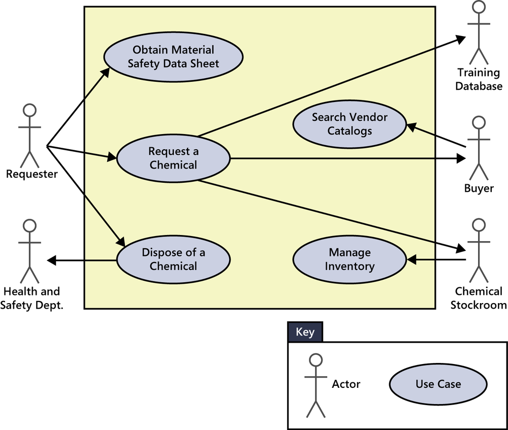
Use case diagrams provide a high-level visual representation of the user requirements. Figure 8-2 shows a partial use case diagram for the CTS, using the Unified Modeling Language (UML) notation ([ref025]; [ref188]). The box frame represents the system boundary. Arrows from each actor (stick figure) connect to the use cases (ovals) with which the actor interacts. An arrow from an actor to a use case indicates that he is the primary actor for the use case. The primary actor initiates the use case and derives the main value from it. An arrow goes from a use case to a secondary actor, who participates somehow in the successful execution of the use case. Other software systems often serve as secondary actors, contributing behind the scenes to the use case execution. The Training Database is just such a secondary actor in Figure 8-2. This system gets involved when a Requester is requesting a hazardous chemical that requires the Requester to have been trained in how to safely handle such dangerous materials.
Compare this use case diagram to the context diagram shown earlier in Figure 5-6 in Chapter 5. Both define the scope boundary between objects that lie outside the system and things inside the system. In the use case diagram, the box separates some internal aspects of the system—use cases—from the external actors. The context diagram also depicts objects that lie outside the system, but it provides no visibility into the system internals. The arrows in a context diagram indicate the flow of data, control signals, or physical materials (if you defined the “system” to include manual processes) across the system boundary. In contrast, the arrows in a use case diagram simply indicate the connections between actors and use cases in which they participate; they do not represent a flow of any kind. As with all forms of requirements representations, all readers of the models you create must have a consistent understanding of the notations used.
Use cases and usage scenarios
A use case describes a discrete, standalone activity that an actor can perform to achieve some outcome of value. A use case might encompass a number of related activities having a common goal. A scenario is a description of a single instance of usage of the system. A use case is therefore a collection of related usage scenarios, and a scenario is a specific instance of a use case. When exploring user requirements, you can begin with a general use case statement and develop more specific usage scenarios, or you can generalize from a specific scenario example to the broader use case.
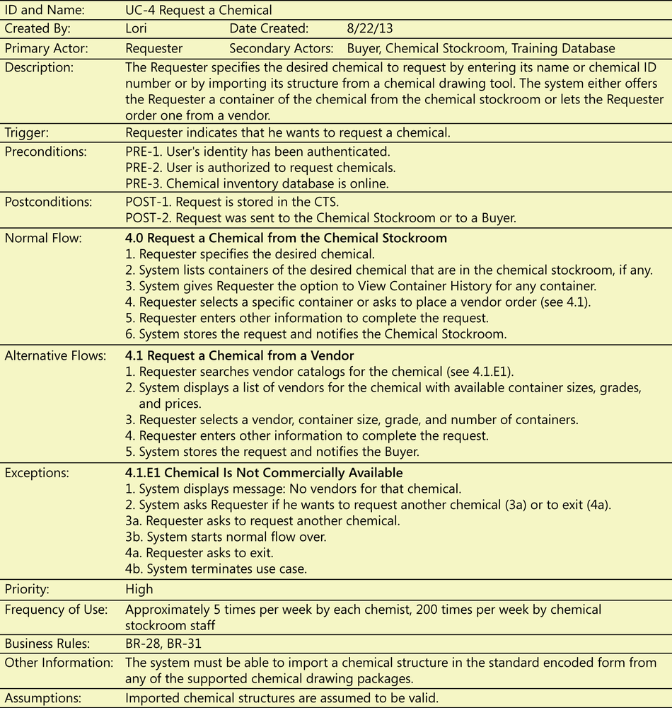
Figure 8-3 shows a comprehensive use case template filled in with an example drawn from the Chemical Tracking System. Appendix D shows more sample use cases written according to this template. As with all templates, you don’t complete this from top to bottom, and you don’t necessarily need all of the template information for every use case. The template is simply a structure in which to store the information you encounter during a use case discussion in an organized and consistent fashion. The template reminds you of all the information you should contemplate regarding each use case. If information that belongs in the template already exists somewhere else, simply point to it to include that information by reference. For instance, don’t incorporate the actual text of each business rule that affects the use case in the template; just list the identifiers for the relevant business rules so the reader can find that information when necessary.
The essential elements of a use case are the following:
A unique identifier and a succinct name that states the user goal
A brief textual description that describes the purpose of the use case
A trigger condition that initiates execution of the use case
Zero or more preconditions that must be satisfied before the use case can begin
One or more postconditions that describe the state of the system after the use case is successfully completed
A numbered list of steps that shows the sequence of interactions between the actor and the system—a dialog—that leads from the preconditions to the postconditions
Preconditions and postconditions
Preconditions define prerequisites that must be met before the system can begin executing the use case. The system should be able to test all preconditions to see if it’s possible to proceed with the use case. Preconditions could describe the system state (for a use case to withdraw cash from an automated teller machine, the ATM must contain money), but they don’t describe the user’s intent (“I need some cash”).
When the system detects the trigger event that indicates that a user wants to execute a particular use case, the system says to itself (though not necessarily to the user!), “Hold on a moment while I check these preconditions.” The trigger event itself is not one of the preconditions. If the preconditions are all satisfied, the system can begin executing the use case; otherwise, it cannot. Checking preconditions can prevent some errors that might otherwise take place if the system knows at the outset that it can’t successfully complete the use case but proceeds anyway. If the ATM is empty, it shouldn’t let a user even begin a withdrawal transaction. This is a way to make your applications more robust. Users aren’t likely to be aware of all of a use case’s preconditions, so the BA might need to get some input from other sources.
Postconditions describe the state of the system after the use case executed successfully. Postconditions can describe:
Something observable to the user (the system displayed an account balance).
Physical outcomes (the ATM has dispensed money and printed a receipt).
Internal system state changes (the account has been debited by the amount of a cash withdrawal, plus any transaction fees).
Many postconditions are evident to the user, because they reflect the outcome that delivers user value: “I’ve got my cash!” However, no user will ever tell a BA that the system should reduce its record of the amount of cash remaining in the ATM by the amount the user just withdrew. Users neither know nor care about such internal housekeeping details. But developers and testers need to know about them, which means that the BA needs to discover those—perhaps by working with a subject matter expert—and record them as additional postconditions.
Normal flows, alternative flows, and exceptions
One scenario is identified as the normal flow of events for the use case. It’s also called the main flow, basic flow, normal course, primary scenario, main success scenario, sunny-day scenario, and happy path. The normal flow for the “Request a Chemical” use case is to request a chemical that’s available in the chemical stockroom. As Figure 8-3 illustrates, the normal flow is written as a numbered list of steps, indicating which entity—the system or a specific actor—performs each step.
Other success scenarios within the use case are called alternative flows or secondary scenarios. Alternative flows deliver the same business outcome (sometimes with variations) as the normal flow but represent less common or lower-priority variations in the specifics of the task or how it is accomplished. The normal flow can branch off into an alternative flow at some decision point in the dialog sequence; it might (or might not) rejoin the normal flow later. The steps in the normal flow indicate where the user can branch into an alternative flow. A user who says, “The default should be…” is describing the normal flow of the use case. A statement such as “The user should also be able to request a chemical from a vendor” suggests an alternative flow, shown as 4.1 in Figure 8-3, which branches from step 4 in the normal flow.
Recall that user stories are concise statements of user needs, in contrast to the richer description that a use case provides. In the agile world, a user story sometimes covers the same scope as an entire use case, but in other cases a user story represents just a single scenario or alternative flow. If an agile development team were discussing requirements for the CTS, they might come up with user stories such as the following:
As a chemist, I want to request a chemical so that I can perform experiments.
As a chemist, I want to request a chemical from the Chemical Stockroom so that I can use it immediately.
As a chemist, I want to request a chemical from a vendor because I don’t trust the purity of any of the samples available in the Chemical Stockroom.
The first of these three stories corresponds to the use case as a whole. The second and third user stories represent the normal flow of the use case and the first alternative flow, from Figure 8-3.
Conditions that have the potential to prevent a use case from succeeding are called exceptions. Exceptions describe anticipated error conditions that could occur during execution of the use case and how they are to be handled. In some cases, the user can recover from an exception, perhaps by re-entering some data that was incorrect. In other situations, though, the use case must terminate without reaching its success conditions. One exception for the “Request a Chemical” use case is “Chemical Is Not Commercially Available,” labeled as 4.1.E1 in Figure 8-3. If you don’t specify exception handling during requirements elicitation, there are two possible outcomes:
It’s a safe bet that system crashes aren’t on the user’s list of requirements.
Some error conditions could affect multiple use cases or multiple steps in a use case’s normal flow. Examples are a loss of network connectivity, a database failure partway through an operation, or a physical device failure such as a paper jam. Treat these as additional functional requirements to be implemented, instead of repeating them as exceptions for all the potentially affected use cases. The goal is not to force-fit all known functionality into a use case. You’re employing usage-centric elicitation to try to discover as much of the essential system functionality as you can.
You won’t necessarily implement every alternative flow that you identify for a use case. You might defer some to later iterations or releases. However, you must implement the exceptions that can prevent the flows that you do implement from succeeding. Experienced programmers know that handling exceptions represents a lot of the coding effort. Overlooked exceptions are a common source of missing requirements. Specifying exception conditions during requirements elicitation helps teams build robust products. The steps in the normal flow indicate where known exceptions could take place, pointing to the section in the use case template for how the system should handle the exception.
Agile projects employing the user story approach address exceptions through the acceptance tests they create for each story. The third user story above pertained to requesting a chemical from a vendor. Conversations about this story might raise questions such as, “What if the chemical you want is not commercially available from any vendor?” This could lead to an acceptance test like, “If the chemical isn’t found in any available vendor catalogs, show a message to that effect.” As with any good testing approach, the set of acceptance tests for a user story must cover both expected behavior and things that could go wrong.
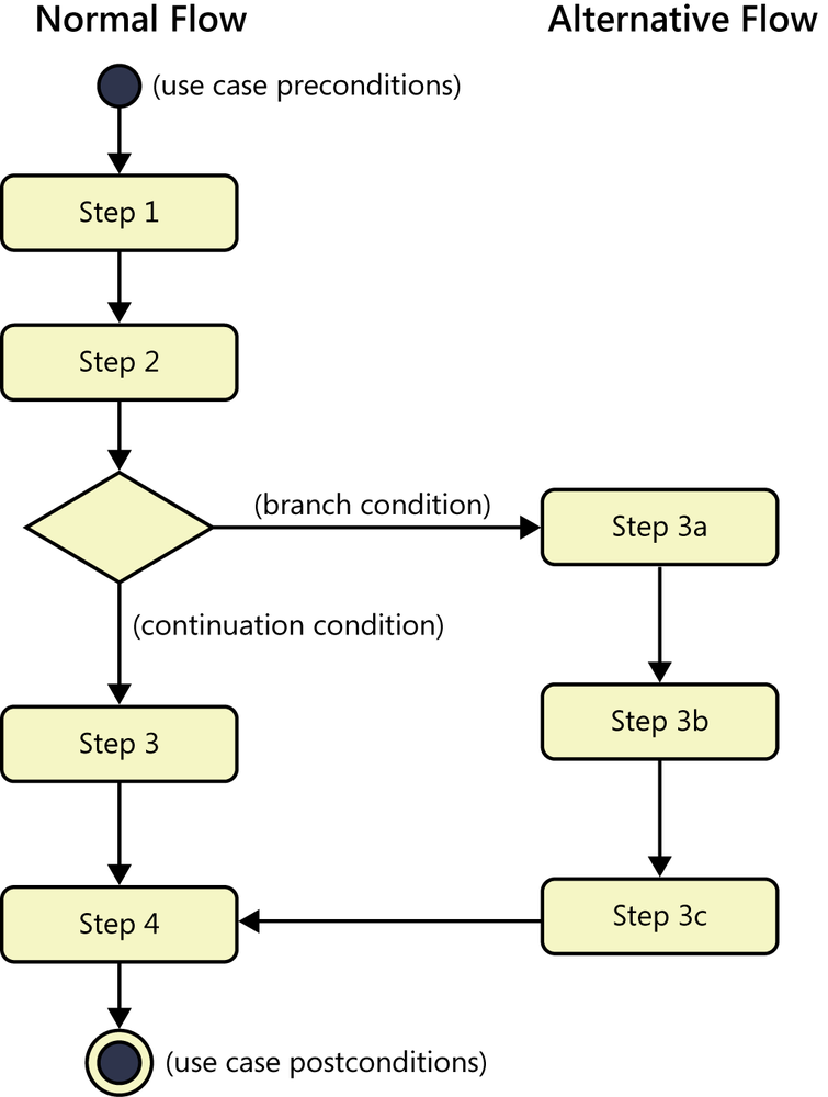
Although many use cases can be described in simple prose, a flowchart or a UML activity diagram is a useful way to visually represent the logic flow in a complex use case, as illustrated in Figure 8-4. Flowcharts and activity diagrams show the decision points and conditions that cause a branch from the normal flow into an alternative flow.
In the example in Figure 8-3, the actor’s ultimate goal—to request a chemical—is the same in both situations. Therefore, requesting a chemical from the stockroom or from a vendor are two scenarios within the same use case, not separate use cases. Some of the steps in an alternative flow will be the same as those in the normal flow, but certain unique actions are needed to accomplish the alternative path. This alternative flow might allow the user to search vendor catalogs for a desired chemical, then rejoin the normal flow and continue with the requesting process back at step 4.
Extend and include
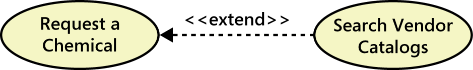
You can show two types of relationships, called extend and include, between use cases in a use case diagram. Figure 8-3 showed that the normal flow for the “Request a Chemical” use case is to request a chemical from the Chemical Stockroom; an alternative flow is to request a chemical from a vendor. In the use case diagram in Figure 8-2, the Buyer has a use case called “Search Vendor Catalogs.” Suppose you wanted to let the Requester execute that same “Search Vendor Catalog” use case as an option when requesting a chemical, as part of the alternative flow processing. A use case diagram can show that a standalone use case like “Search Vendor Catalogs” extends the normal flow into an alternative flow, as illustrated in Figure 8-5 ([ref009]).
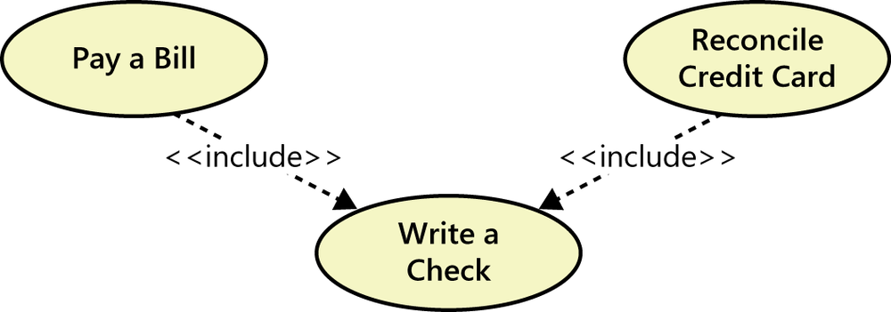
Sometimes several use cases share a common set of steps. To avoid duplicating these steps in each such use case, you can define a separate use case that contains the shared functionality and indicate that the other use cases include that subordinate use case. This is analogous to calling a common subroutine in a computer program. Consider an accounting software package. Two use cases are “Pay a Bill” and “Reconcile Credit Card,” both of which might involve the user writing a check to make the payment. You can create a separate use case called “Write a Check” that contains the common steps involved in writing the check. The two transaction use cases both include the “Write a Check” use case, as shown with the notation in Figure 8-6. “Write a Check” is a standalone use case, because that’s another task someone might perform with the accounting software.
Aligning preconditions and postconditions
In many applications, the user can chain together a sequence of use cases into a “macro” use case that describes a larger task. Some use cases for an e-commerce website might be “Search Catalog,” “Add Item to Shopping Cart,” and “Pay for Items in Shopping Cart.” If you could perform each of these activities independently, they are individual use cases. That is, you could have one session with the website in which you just searched the catalog, a second session in which you just added an item to your shopping cart without searching (perhaps by typing in the product number), and a third session in which you paid for the items in the shopping cart (implying that your cart must persist across logon sessions). However, you might also be able to perform all three activities in sequence as a single large use case called “Buy Product,” as shown in Figure 8-7. The description of the “Buy Product” use case could simply say to perform each of those other three use cases in turn: “Search Catalog,” “Add Item to Shopping Cart,” and then “Pay for Items in Shopping Cart.”
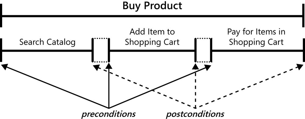
To make this process work, each use case must leave the system in a state that enables the user to commence the next use case immediately. That is, the postconditions of one use case must satisfy the preconditions of the next one in the sequence. Similarly, in a transaction-processing application such as an ATM, each use case must leave the system in a state that permits the next transaction to begin.
Use cases and business rules
Use cases and business rules are intertwined. Some business rules constrain which roles can perform all or parts of a use case. Perhaps only users who have certain privilege levels can perform specific alternative flows. That is, the rule might impose preconditions that the system must test before letting the user proceed. Business rules can influence specific steps in the normal flow by defining valid input values or dictating how computations are to be performed. Suppose an airline charges a premium for passengers who want certain preferred seats. If the passenger executes a use case to select a new seat on the airline’s website, the relevant business rules would change the passenger’s airfare if he chooses one of those seats. When specifying a use case, record the identifiers of any known business rules that affect the use case, and indicate which part of the use case each rule affects.
While you are exploring use cases you might uncover pertinent business rules. When the chemists who participated in requirements elicitation for the Chemical Tracking System discussed the use case to view an order stored in the system, one of them said, “Fred shouldn’t be able to see my orders, and I don’t want to see Fred’s orders.” That is, they came up with a business rule: a user may view only chemical orders that he placed. Sometimes you invent business rules during elicitation and analysis, sometimes your discussions reveal relevant rules that already exist in the organization, and sometimes you already know about existing rules that the system will have to respect.
Identifying use cases
You can identify use cases in several ways ([ref100]; [ref147]):
Identify the actors first, then lay out the business processes being supported by the system, and define the use cases for activities where actors and systems interact.
Create a specific scenario to illustrate each business process, then generalize the scenarios into use cases and identify the actors involved in each one.
Using a business process description, ask, “What tasks must the system perform to complete this process or convert the inputs into outputs?” Those tasks might be use cases.
Identify the external events to which the system must respond, then relate these events to participating actors and specific use cases.
Use a CRUD analysis to identify data entities that require use cases to create, read, update, delete, or otherwise manipulate them (see Chapter 13).
Examine the context diagram and ask, “What objectives do each of these external entities want to achieve with the help of the system?”
The CTS team followed the first approach, using the process described in the next several sections of this chapter. The three business analysts facilitated a series of two-hour use case elicitation workshops, which were held twice a week. They chose to use workshops for elicitation partly because none of them had tried the use case method before, so they needed to learn together. Also, they saw the value of group synergy in the workshop format over individual interviews. Members of the various user classes participated in separate, parallel workshops, working with different BAs. This worked well because only a few use cases were common to multiple user classes. Each workshop included the user class’s product champion, other selected user representatives, and a developer. Participating in elicitation workshops gives developers early insight into the product they will be expected to build. Developers also serve as the voice of reality when infeasible requirements are suggested.
Prior to beginning the workshops, each BA asked the users to think of tasks they would need to perform with the new system. Each of these tasks became a candidate use case. This is a bottom-up approach to use case elicitation, which complements the top-down strategy of identifying all the business processes the system will support and gleaning use cases from those. Comparing the lists of use cases generated from these different thought processes reduces the chance of overlooking one.
A few candidates were judged to be out of scope and weren’t pursued. As the group explored the remaining in-scope use cases in the workshops, they found that some of them were related scenarios that could be consolidated into a single, more general use case. The group also discovered additional use cases beyond those in the initial set. Expect to perform these sorts of adjustments as you go along.
Some users proposed use cases that were not phrased as tasks, such as “Material Safety Data Sheet.” A use case’s name should indicate a goal the user wants to accomplish, so you need to start with a verb. Does the user want to request, view, print, download, order, revise, delete, or create a material safety data sheet? Sometimes a suggested use case was just a single step the actor would perform as part of process, such as “Scan Bar Code.” The BA needs to learn what objective the user has in mind that involves scanning a bar code. The BA might ask, “When you scan the bar code on the chemical container, what are you trying to accomplish?” Suppose the reply is, “As a chemist, I need to scan the container’s bar code so I can log the chemical into my laboratory.” (Note how this is stated in the style of a user story.) The real use case, therefore, is “Log Chemical into Lab.” Scanning the bar code label is just one step in the interaction between the actor and the system that logs the chemical into the lab.
Don’t dive into high-resolution analysis of the first use case that someone proposes. Learn just enough about each use case so the team can prioritize them and do an initial allocation of use cases, or portions thereof, to forthcoming releases or iterations. Then you can begin exploring the highest-priority use cases, those that are allocated to the next development cycle, so developers can begin implementing them as soon as possible. Lower-priority use cases can wait for detailing until just before they’re scheduled to be implemented. This is the same strategy you would pursue when working with user stories on an agile project.
Exploring use cases
The participants in the CTS elicitation workshops began each use case discussion by identifying the actor who would benefit from the use case and writing the short description. Estimating the frequency of use provided an early indicator of concurrent usage and capacity requirements. Then they began defining the preconditions and postconditions, which are the boundaries of the use case; all use case steps take place between these boundaries. The preconditions and postconditions were adjusted as more information surfaced during the discussion.
Next, the BA asked the participants how they envisioned interacting with the system to perform the task. The resulting sequence of actor actions and system responses became the normal flow for the use case. Although each participant had a different mental image of what the future user interface would look like, the group reached a common vision of the essential steps in the actor-system dialog.
The BA captured the actor actions and their corresponding system responses on sticky notes, which he placed on a flipchart sheet. Sticky notes work well for such workshops. It’s easy to move them around, group them together, and replace them as the discussion progresses. Another way to conduct such a workshop is to project a use case template onto a large screen from a computer and populate the template during the discussion. The elicitation team developed similar dialogs for the alternative flows and exceptions. Many exceptions were discovered when the analyst asked questions similar to “What should happen if the database isn’t online at that moment?” or “What if the chemical isn’t commercially available?” The workshop is also a good time to discuss the user’s expectations of quality, such as response times and availability, security requirements, and UI design constraints.
After the workshop participants described each use case and no one proposed additional variations, exceptions, or other information, they moved on to another one. They didn’t try to cover all the use cases in one marathon workshop or to pin down every detail of every use case they discussed. Instead, they explored the use cases in layers, beginning with the broad strokes for the top-priority use cases and iteratively refining them just prior to implementation.
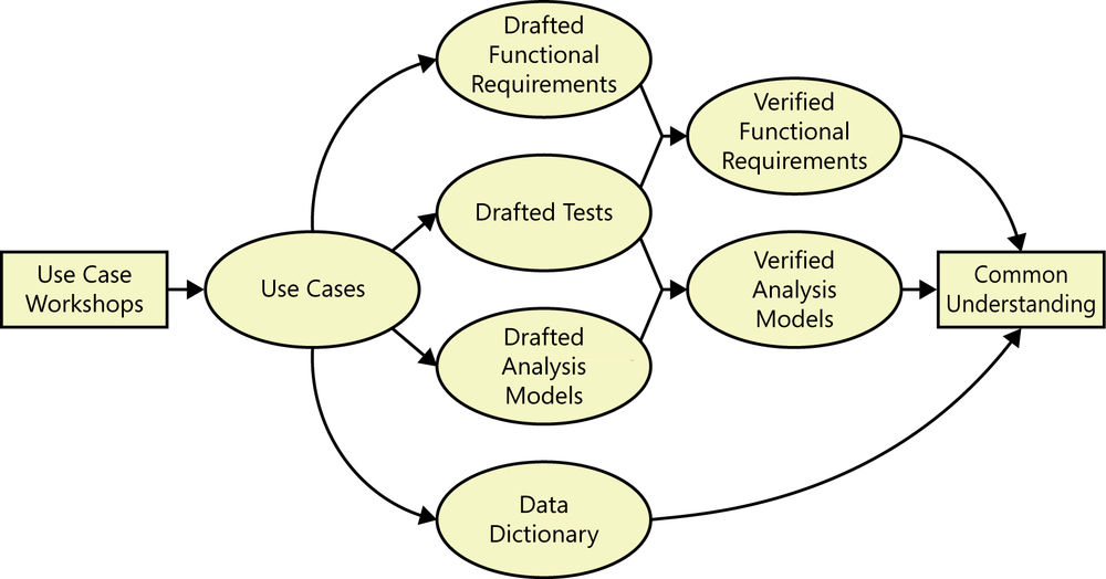
Figure 8-8 shows the sequence of work products created during the CTS use case elicitation process. Following the workshop, the analyst documented each use case by using the template illustrated in Figure 8-3, using his judgment to decide how complete the template needed to be for each use case.
When writing the steps in the use case flows, avoid language that refers to specific user interface interactions. “Requester specifies the desired chemical” is nicely general and UI-independent. It allows for multiple ways to accomplish the user’s intention of indicating the chemical to be requested: enter a chemical ID number, import a chemical structure from a file, draw the structure on the screen with the mouse (or a stylus on a tablet), or select a chemical from a list. Proceeding too quickly into specific interaction details constrains the thinking of the workshop participants.
Use cases often involve some additional information or requirements that do not fit within any of the template sections. Use the “Other Information” section to record pertinent performance and other quality requirements, constraints, and external interface knowledge. Eventually, all this information should find a home in the SRS or other elements of your requirements documentation. Also note any information that might not be visible to the users, such as the need for one system to communicate behind the scenes with another to complete the use case.
Validating use cases
The process in Figure 8-8 shows that after each workshop, the BAs on the Chemical Tracking System derived software functional requirements from the use cases. (For more about this, see the next section, Use cases and functional requirements.) The BAs also drew some analysis models, such as a state-transition diagram that showed all possible chemical request statuses and the permitted status changes. Multiple use cases can manipulate a chemical request, so the diagram pulls together information and operations that span several use cases. Chapter 12 illustrates several analysis models for the CTS; the state-transition diagram is in Figure 12-3.
A day or two after each workshop, the BA gave the use cases and functional requirements to the workshop participants, who reviewed them prior to the next workshop. These informal reviews revealed many errors: previously undiscovered alternative flows, new exceptions, incorrect functional requirements, and missing dialog steps. The team quickly learned to allow at least one day between successive workshops. The mental relaxation that comes after a day or two away allows people to examine their earlier work from a fresh perspective. One BA who held daily workshops found that the participants had difficulty spotting errors in the materials they reviewed because the information was too fresh in their minds. They mentally recited the recent discussion and didn’t see the errors.
Trap
Don’t wait until requirements specification is complete to solicit review feedback from users, developers, and other stakeholders. Early reviews help improve the subsequent requirements work.
Early in requirements development, the Chemical Tracking System’s test lead began creating conceptual tests—independent of implementation and user-interface specifics—from the use cases ([ref046]). These tests helped the team reach a shared understanding of how the system should behave in specific scenarios. The tests let the BAs verify whether they had derived the functionality needed to let users perform each use case. During the final elicitation workshop, the participants walked through the tests together to be sure they agreed on how the use cases should work.
Early conceptual test thinking like this is much cheaper and faster than writing code, building part of the system, executing tests, and only then discovering problems with requirements. It is analogous to the agile approach of fleshing out user stories with acceptance tests, but the CTS team wrote both functional requirements and tests. Comparing the two revealed errors in both before any code was written. Chapter 17 discusses generating tests from requirements.
The CTS team created multiple representations of the requirements they identified: a list of functional requirements, a set of corresponding tests, and analysis models, all based on use cases. Comparing these alternative views of the requirements is a powerful quality technique ([ref247]). The team used the tests to verify the functional requirements, looking for tests that couldn’t be “executed” with the set of requirements and for requirements that were not covered by tests.
If you create just a single representation, or view, of the requirements, you must trust it. You have nothing to compare it against to look for errors, gaps, and different interpretations. Agile project teams do not typically document functional requirements, preferring to create acceptance tests. Although thinking about testing during requirements exploration is an excellent idea on every project, it still leaves you with only a single representation of the requirements that you must trust as being correct. Similarly, traditional project teams that create only a set of functional requirements and leave testing until later in the project have only one representation. You’ll get the best results with a judicious combination of written requirements, tests, analysis models, and prototypes.
Use cases and functional requirements
Software developers don’t implement business requirements or user requirements. They implement functional requirements, specific bits of system behavior. Some practitioners regard the use cases as being the functional requirements. However, we have seen many organizations get into trouble when they simply pass their use cases to developers for implementation. Use cases describe the user’s perspective, looking at the externally visible behavior of the system. They don’t contain all the information that a developer needs to write the software. The user of an ATM doesn’t know about any back-end processing involved, such as communicating with the bank’s computer. This detail is invisible to the user, yet the developer needs to know about it. Developers who receive even fully dressed use cases often have many questions. To reduce this uncertainty, consider having a BA explicitly specify the functional requirements necessary to implement each use case ([ref008]).
Many functional requirements fall right out of the dialog steps between the actor and the system. Some are obvious, such as “The system shall assign a unique sequence number to each request.” There is no point in duplicating those elsewhere if they’re clear from the use case. Other functional requirements don’t appear in the use case description. For instance, the way use cases are typically documented does not specify what the system should do if a precondition is not satisfied. This is an example of how use cases often do not provide all the necessary information for a developer to know what to build. The BA must derive those missing requirements and communicate them to developers and testers ([ref247]). This analysis to get from the user’s view of the requirements to the developer’s view is one of the many ways the BA adds value to a project.
The Chemical Tracking System employed the use cases primarily as a tool to reveal the necessary functional requirements. The analysts wrote only casual descriptions of the less complex use cases. They then derived all the functional requirements that, when implemented, would allow an actor to perform the use case, including alternative flows and exception handlers. The analysts documented these functional requirements in the SRS, which was organized by product feature.
You can document the functionality associated with a use case in several ways. None of the following methods is perfect, so select the approach that best fits with how you want to document and manage your project’s software requirements.
Use cases only
One possibility is to include the functional requirements along with each use case specification, if they aren’t already evident. You’ll still need to document nonfunctional requirements and any functionality that’s not associated with a use case. Additionally, several use cases might need the same functional requirement. If five use cases require that the user’s identity be authenticated, you don’t want to write five different blocks of code for that purpose. Rather than duplicate them, cross-reference functional requirements that appear in multiple use cases. The use cases could be collected in a user requirements document.
Use cases and functional requirements
Another option is to write fairly simple use cases and document the functional requirements derived from each one in an SRS or a requirements repository. In this approach, you should establish traceability between the use cases and their associated functional requirements. That way, if a use case changes, you can quickly find the affected functional requirements. The best way to manage the traceability is with a requirements management tool.
Functional requirements only
One more option is to organize your functional requirements by use case or by feature, and include both the use cases and the functional requirements in the SRS or requirements repository. This is the approach that the CTS team used, and we’ve done the same on several website development projects. We wrote most of our use cases in very concise form, not completing the full template from Figure 8-3. The details were then specified through a set of functional requirements. This approach doesn’t result in a separate user requirements document.
Use cases and tests
If you write both detailed use case specifications and functional requirements, you might notice some duplication, particularly around the normal flow. There is little value in writing the same requirement twice. So another strategy is to write fairly complete use case specifications, but then write acceptance tests to determine if the system properly handles the basic behavior of the use case, alternative success paths, and the various things that could go wrong.
Use case traps to avoid
As with any software engineering technique, there are many ways to go astray when applying the use case approach ([ref161]; [ref146]). Watch out for the following traps:
Too many use cases. If you’re caught in a use case explosion, you might not be writing them at the appropriate level of abstraction. Don’t create a separate use case for every possible scenario. You’ll typically have many more use cases than business requirements and features, but many more functional requirements than use cases.
Highly complex use cases. I once reviewed a use case with four dense pages of dialog steps, with a lot of embedded logic and branching conditions. It was incomprehensible. I’ve heard of even longer use cases, going on page after page. You can’t control the complexity of the business tasks, but you can control how you represent them in use cases. Select one success path through the use case and call that the normal flow. Use alternative flows for the other logic branches that lead to success, and use exceptions to handle branches that lead to failure. You might have many alternatives, but each one will be short and easy to understand. If a flow exceeds 10 to 15 steps in length, confirm whether it truly describes just a single scenario. Don’t arbitrarily split a legitimately long flow just because it has a lot of steps, though.
Including design in the use cases. Use cases should focus on what the users need to accomplish with the system’s help, not on how the screens will look. Emphasize the conceptual interactions between the actors and the system. For example, say “System presents choices” instead of “System displays drop-down list.” Don’t let the UI design drive the requirements exploration. Use screen sketches and dialog maps (see Chapter 12) to help visualize the actor-system interactions, not as firm design specifications.
Including data definitions in the use cases. Use case explorations naturally stimulate data discussions, thinking about what data elements serve as inputs and outputs during the interaction. Some use case authors include definitions of the pertinent data elements right in the use case specification. This makes it difficult for people to find the information because it isn’t obvious which use case contains each data definition. It can also lead to duplicate definitions, which get out of sync when one instance is changed and others are not. Store data definitions in a project-wide data dictionary and data model, as discussed in Chapter 13.
Use cases that users don’t understand. If users can’t relate a use case to their business processes or goals, there’s a problem. Write use cases from the user’s perspective, not the system’s point of view, and ask users to review them. Keep the use cases as simple as you can while still achieving the goal of clear and effective communication.
Benefits of usage-centric requirements
The power of both use cases and user stories comes from their user-centric and usage-centric perspective. The users will have clearer expectations of what the new system will let them do than if you take a feature-centric approach. The customer representatives on several Internet development projects found that use cases clarified their notions of what visitors to their websites should be able to do. Use cases help BAs and developers understand the user’s business. Thinking through the actor-system dialogs reveals ambiguity and vagueness early in the development process, as does generating tests from the use cases.
Overspecifying the requirements up front and trying to include every conceivable function can lead to implementing unnecessary requirements. The usage-centric approach leads to functionality that will allow the user to perform certain known tasks. This helps prevent “orphan functionality” that seems like a good idea but that no one uses because it doesn’t relate directly to user goals.
Developing user requirements helps with requirements prioritization. The highest-priority functional requirements are those that originate in the top-priority user requirements. A use case or user story could be of high priority for several reasons:
It describes part of a core business process that the system enables.
Many users will use it frequently.
A favored user class requested it.
It’s required for regulatory compliance.
Other system functions depend on its presence.
Trap
Don’t spend a lot of time detailing use cases that won’t be implemented for months or years. They’re likely to change or disappear before construction begins.
There are technical benefits to use cases, too. They reveal some of the important domain objects and their responsibilities to each other. Developers using object-oriented design methods can turn use cases into object models such as class and sequence diagrams. As business processes change over time, the tasks that are embodied in specific user requirements will change. If you’ve traced functional requirements, designs, code, and tests back to their parent user requirements—the voice of the user—it will be easier to cascade those changes through the entire system.