
Bearingless induction motors
In this chapter the bearingless induction motor (or induction type bearingless motor) is introduced. In a squirrel cage induction machine, short-circuit paths are constructed in the rotor iron from cast aluminium or fabricated copper in a cage-like structure. The revolving magnetic field set up by the stator winding currents induces voltages in the rotor circuit producing current. Since there is a phase shift between the rotor current and stator field, a torque is generated due to the interaction of the rotor current and the revolving magnetic field. However, in a bearingless induction motor the rotor current causes interference in the suspension force generation if the rotor circuit is not constructed correctly [1,2] i.e., a simple cage, as found in a standard cage induction motor, is not very suitable and modification is recommended. Hence, in the first section, the rotor structure and transfer characteristics are discussed. In the second section, a primitive controller block diagram is given in order to provide the basic concepts of a bearingless induction motor drive employing an indirect field-oriented controller [3,4]. Then an airgap flux-linkage-oriented controller is introduced. In the third section a direct field-oriented controller is put forward [5,6]. This detects the airgap flux linkage from flux sensors or terminal voltage and current. In the final section a comparison between the 2-pole and 4-pole motor drive is made, including the self-excitation phenomenon of the suspension winding [7].
13.1 Rotor structure and suspension force
Figure 13.1(a) shows the typical rotor lamination of a cage induction motor. The circular silicon steel sheet has a centre hole punched for the shaft, and the small holes (or slots) around the circumference are to accommodate the rotor bars for construction of the cage. The rotor slots can be open to the rotor surface or closed depending on the design. Open slots reduce leakage inductance whereas closed slots make casting an aluminium cage more straightforward. For high speed applications the slots are circular and closed for improved rotor robustness. Lamination thickness is typically 0.5, 0.35 mm or thinner. Thin sheets reduce the iron core loss although the manufacturing cost is increased. They form a cylindrical iron stack for the rotor core. In super-high-speed machines the rotor iron core is made from a solid cylindrical piece of iron rather than laminated sheets to enhance shaft stiffness with the sacrifice of rotor losses and performance.
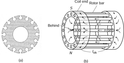
Figure 13.1 Iron core and squirrel cage windings: (a) rotor iron core; (b) squirrel cage rotor windings
Figure 13.1(b) shows the typical short-circuit conductor arrangement of the squirrel cage rotor. The bars are located in the rotor slots with an axial core length of lstk. Two end-rings connect the rotor bars together. The cage, as previously mentioned, is fabricated from copper bars and rings or cast in aluminium. In super-high-speed applications, a copper compound metal is employed to improve robustness but with a conductivity reduction. In most bearingless induction motors the rotor structure is more complex than the simple cage arrangement shown in Figure 13.1(b) and, since they are still prototype machines, the rotor cage is fabricated from copper bars, inserted into the core and connected by copper end-pieces (end-ring sections), which are braised or soldered on. This is the easiest way to fabricate a prototype rotor.
Suppose that a 2-pole revolving magnetic field is applied to a squirrel cage rotor. Electromotive forces (EMFs) are induced so that a 2-pole current distribution is generated in the rotor short circuit (the cage). The arrows in Figure 13.1(b) show the direction of the current flow at an instance in time. The current in the short circuits generate a 2-pole flux wave as indicated by N and S in the figure. The 2-pole flux rotates at the slip frequency with respect to the rotor reference frame (i.e., a reference frame rotating at rotor speed) in steady-state conditions where slip frequency = slip × supply frequency. Torque is generated as a product of the rotor current and magnetic field. To enhance torque, low resistance in the rotor circuit is necessary. If a 4-pole revolving magnetic field is also applied to the squirrel cage rotor then a 4-pole current distribution flows in the rotor short circuits. Hence the squirrel cage rotor can generate torque for both the 4-pole and 2-pole revolving magnetic fields (and even higher pole numbers) and it is not pole-specific.
A standard squirrel cage rotor causes problems when used in a bearingless induction machine to generate a suspension force. Suppose that an additional 2-pole winding is used for suspension force generation. For a step change in suspension force there has to be a step change in the 2-pole stator flux. Because voltage is induced into the rotor circuit, which generates rotor current, the rotor flux does not change suddenly. Hence the interaction of stator (primary) and rotor (secondary) circuits produces a delay in the 2-pole flux which in turn delays the suspension force response. In addition to the response delay, the rotor current also makes alignment of the flux – hence the force is also difficult to orientate.
To overcome the problems associated with the squirrel cage rotor, a pole-specific short circuit can be used. Figure 13.2(a) shows a pole-specific rotor short circuit for a 2-pole induction motor. Two rotor bars are connected by two end-rings. If a rotating 2-pole magnetic field is generated in the airgap by the stator winding currents, as indicated by N and S, EMFs are induced and current is generated in the rotor; with the flow shown by the arrows. If a 4-pole revolving magnetic field is applied, rotor current does not flow because the net rotor flux linkage between the bars is zero since the N and S poles linking to the short circuit cancel each other out, and the EMFs induced into the short circuits sum to zero. Hence the short circuit is 2-pole pole-specific. If a rotor has 16 slots then eight short circuits should be constructed so that eight end-rings are required at each end. These eight short circuits need to be isolated.
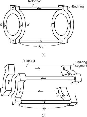
Figure 13.2(b) shows a 4-pole pole-specific short circuit. The four rotor bars are connected by four end-ring segments (rather than complete rings) – two at each end – to form one short circuit. If the current flows in the direction indicated by the arrows then a 4-pole magnetic field is generated in the airgap. If there are 16 slots in the rotor core then 4 short circuits should be constructed with a mechanical phase-shift angle of 22.5 deg. If a 4-pole revolving magnetic field is applied then current is generated in the short circuits. However, there is no current when a 2-pole revolving magnetic field is applied because the EMFs induced into the circuits sum to zero.
Now, let us go back and consider a standard cage rotor to understand why it is impractical in a bearingless induction machine application. Figure 13.3 shows equivalent circuits for a bearingless induction motor with both 4-pole and 2-pole 3-phase windings. Rs and Rr are the stator and rotor resistances, ls and lr are stator and rotor leakage inductances and Lm and Rm are the magnetizing inductance and iron loss resistance. The subscripts 2 and 4 indicate the 2-pole and 4-pole windings. The slip is s2 for the 2-pole and s4 for the 4-pole winding current. These equivalent circuits are usually used for steady-state characteristics calculation in conventional induction motors driven with sinusoidal voltage and current.
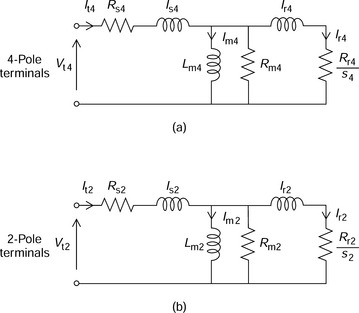
Figure 13.3 Equivalent circuits of the bearingless induction motor: (a) equivalent circuit of 4-pole winding terminals; (b) equivalent circuit of 2-pole winding terminals
Let us suppose that the 4-pole and 2-pole windings are assigned as the motor and suspension force windings respectively. When no torque is generated, s4 is zero resulting in a high value (infinity) of the effective resistance Rr4/s4 so that Ir4 is zero (i.e., there is no rotor current) and the terminal current It4 is equal to excitation current Im4, assuming that iron loss is negligible. Note that the excitation current Im4 generates the airgap flux.
When torque is required, s4 increases and Rr4/s4 decreases so that we now get a rotor current Ir4. Torque is the product this rotor current and the stator component of the airgap flux. The airgap flux is mostly determined by the airgap length as well as the saturation of the rotor and stator iron material. Rr4/s4 can be split into Rr4 (rotor resistance, i.e., rotor copper loss = I2t4Rr4) and Rr4 × (1 − s4)/s4 (electromechanical energy conversion = I2t4Rr4 × (1 − s4)/s4). Therefore Rr4 and s4 are normally designed to be as small as possible at rated power for efficient operation (though there is often a compromise with the starting torque requirement, which requires a higher rotor resistance). For general-purpose 3-phase induction motors with ratings of a few kW (connected to a standard fixed-frequency supply), the rated slip s4 is in the range of 0.02 (standard cage-rotor motors) to 0.1 (wound-rotor and specialized machines). For high speed or large motors (which are usually higher in efficiency), s4 decreases to perhaps 0.005 or even less. If the rotor shaft rotational speed is ωrm then the slip for the 4-pole winding is
where ω4 is the frequency (in rad/s) of the 4-pole winding voltage and current. If a squirrel cage rotor is employed, the rotor bars and end-rings are optimized to make Rr4 (and also Rr2) as small as possible. For the 2-pole winding, the slip is
where ω2 is frequency of the 2-pole winding voltage and current. The 4-pole winding is assigned as the motor winding so that, at low slip, ωrm ≈ ω4/2. For static suspension force generation, the current frequency of the windings should be equal so that ω2 = ω4, hence s2 = 0.5. This is a high slip so that the rotor current is the dominant component of the terminal current It2 rather than the excitation current Im2. This leads to a very inefficient machine and problems with the suspension force generation.
The 4-pole and 2-pole winding fluxes are generated by the excitation currents Im4 and Im2. Im4 is usually kept constant to provide excitation for torque generation so that Im2 is proportional to the suspension force. To regulate the excitation current, the terminal current It2 is controlled by a regulator. The current transfer function Im2/It2 is
where
and
This transfer function illustrates that the first pole frequency is ωa2 and the amplitude starts to role off at a rate of −20 dB/dec. The second pole frequency ωb2 is between 12 and 20 times higher than the first pole frequency since lr2/Lm2 is in the range of 0.05–0.08. The suspension force response is influenced by this current transfer function.
Next, let us consider the case when a pole-specific rotor is employed. If a 4-pole arrangement is employed then Rr2 is infinite because there is no 2-pole rotor current due to the 2-pole revolving magnetic field. Hence the excitation current is proportional to the terminal current It2 (neglecting iron loss). Therefore the transfer function Im2/It2 is unity. In practice Im2/It2 decreases at high frequency because of the iron loss. However, the frequency at this point is usually high enough to not affect the mechanical dynamics.
In Figure 13.4, the curves show the phase angle characteristics. The curve for the squirrel cage rotor is calculated using (13.3) while the curve for the pole-specific rotor includes the iron loss resistance. Note that the pole-specific rotor exhibits a better transfer function. The data points indicate experimental results for verification. A static suspension force is applied to the test machine and the direction of the suspension force command vector is obtained. At zero speed, the suspension force command is exactly opposite to the applied suspension force. As the speed increases, the suspension force command is automatically generated with a phase-lead angle to compensate for the phase lag of the generated suspension force. The command amplitude also increases to compensate for the decrease in gain. For the cage rotor, at a speed of about 5 rev/s, the phase lag angle is too large to maintain magnetic suspension. However, the pole-specific rotor provides a good frequency characteristic.
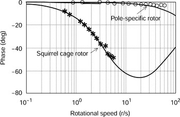
When the roles of the 4-pole and 2-pole windings are reversed, i.e., when the 2-pole winding is assigned as the motor winding, the transfer function of the squirrel cage improves but the pole-specific rotor is still superior.
13.2 Indirect type drives
In this section the indirect type of bearingless induction motor drive is introduced. A primitive controller structure is first considered for ease of understanding. The controller structure is almost the same as that used for the primitive bearingless motor except for amplitude and phase angle compensation of the motor winding current. This controller is valid under steady-state conditions. For fast response, an airgap field-oriented controller is then introduced. It is found that the airgap flux linkage is regulated even under fast acceleration during a short transient over-current period.
Figure 13.5 shows the block diagram of a primitive controller. The controller is divided into two parts: one is a radial position controller and the other is a motor controller. The motor controller structure is slightly different from that of the primitive bearingless motor although the radial position controller has the same structure. The bearingless machine has 4-pole and 2-pole windings designated as motor and suspension force windings respectively. The mechanical synchronous speed command ω*4m is doubled to generate an electrical synchronous speed command 2ω*4m and the cosine and sine functions of 2ω*4mt are obtained. These functions are the airgap flux linkages and hence they are the commands used for the radial displacement derivatives of airgap flux linkages λ′gc and λ′gs, where λ′gc and λ′gs are proportional to airgap flux linkages λgc and λgs. This assumes that the mutual inductance between the 4-pole and 2-pole windings is proportional to the rotor displacement. Since the amplitudes of the cosine and sine functions are unity, the amplitude of the airgap flux linkage is unity. The orientation of the airgap flux linkage is given by 2ω*4mt. The amplitude and direction of the airgap flux linkage is independently generated and the current amplitude I*mp and phase angle θ* are adjusted so that the actual airgap flux linkage follows the commands λgc and λgs. In the modulation block, suspension currents are generated from suspension force commands, and the amplitudes of flux linkage derivatives are taken to be unity in the calculation.
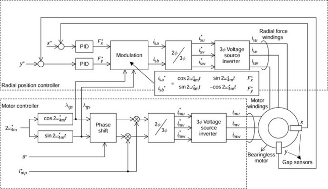
Current commands are generated with an amplitude of I*mp and phase-lead angle of θ*. For example, the u-phase motor current is
The amplitude and phase-lead angle should be adjusted so that the motor airgap flux linkage corresponds to the flux commands λgc and λgs. Since the airgap flux linkage is generated by the excitation current Im4 in Figure 13.3, the line current is obtained from (13.3). Substituting 4 for 2 and solving for It4/Im4 yields
where
and
The amplitude and phase angle of the transfer function of It4/Im4 is shown in Figure 13.6. Note that correspondence of the motor airgap flux linkage with respect to the flux command is realized when the amplitude and phase-lead angle are gradually increased as a function of slip. This fact can be explained from Figure 13.3(a) as follows:
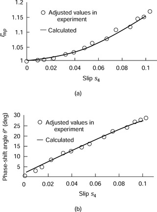
Figure 13.6 Amplitude and phase-shift angle of motor current: (a) current amplitude compensation; (b) current phase-shift angle θ compensation
(a) When the slip is zero, the rotor current is zero so that the terminal current is equal to the excitation current Im4 (neglecting the iron loss current).
(b) As the slip increases, the impedance of Rr4/s4 decreases and the rotor current Ir4 is no longer zero. Since the impedance of the rotor circuit is composed of lr4 and Rr4/s4 in series, but the mutual reactance is the inductance Lm4 only, Ir4 will lead with respect to Im4.
(c) The line current It4 is the phasor sum of the rotor and excitation currents so that It4 is advanced with respect to Im4. The amplitude also increases.
To see the effectiveness of the primitive controller several tests can be carried out. The primitive controller is effective when the motor is generating torque in the following tests [3]:
(a) The suspension force command is decoupled when a static force is applied to a shaft.
(b) No interference in the perpendicular radial axes is seen in a disturbance force suppression test.
(c) The airgap flux linkage commands λgc and λgs correspond to the detected flux waveforms obtained through search coils wound around stator teeth.
These facts indicate that airgap flux linkage components in the bearingless motor correspond to the airgap flux linkage commands.
However, there is a problem if there is a sudden change in rotational speed command 2ω*4m since the primitive controller is only valid under steady-state conditions. In order to realize airgap flux linkage steering during fast acceleration and deceleration in an application, field-oriented control theory is required (which is often referred to as vector control theory).
Figure 13.7 shows an example of the indirect type of a vector controller [8,9]. The controller regulates the airgap flux linkage vector even during transient conditions. The angular speed of the shaft ωrm is detected by a rotary encoder. The shaft speed is multiplied by the number of pole pairs, i.e., 2 for a 4-pole motor winding. Then 2 ωrm is compared with the rotational speed command 2ω*rm and a torque current command iqs is generated through the PI speed controller. An excitation current command idm is given as a constant. The slip frequency 2ωs and d-axis current are generated using the following equations
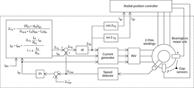
One can see a derivative operator in the numerator of (13.6). However, in a practical system, an integration function is implemented in a later block to counteract this derivative operation. Note that the induction machine parameters, such as the rotor resistance and the mutual and leakage inductances, are required for the indirect vector controller. These parameters may vary with temperature, magnetic saturation or operation point. On-line identification of the machine parameters is possible using several methods, such as a model reference adaptive system, observers and so on. Advanced readers are encouraged to study papers on induction motor parameter identification.
The slip frequency is added to 2ωrm so that the instantaneous speed of the airgap flux linkage 2ω0 is obtained. Integration of the angular speed, i.e.,
provides the instantaneous angular position of airgap flux linkage. The sinusoidal and cosinusoidal functions of 2φ0 provide the components of the airgap flux linkage vectors λgc and λgs respectively. These components are used in the modulation block.
In the current generator, 3-phase symmetrical current commands are generated using the d- and q-axis stator currents ids and iqs, as well as the airgap flux linkage position φ0. For an example, the u-phase motor current is
The v- and w-phase currents have phase shifts of 2π/3. The motor currents are regulated using these instantaneous currents. Hence the rotational angular position of airgap flux linkage in an actual bearingless induction motor should correspond to φ0 and the amplitude of the airgap flux linkage is constant, which is determined by the current command idm. Even in transient conditions, such as during fast acceleration and deceleration, the control is valid.
Figure 13.8 shows the performance during a fast acceleration. A step in speed command 2ω*rm from 1200 to 2700 r/min is given to the bearingless induction machine drive. The torque current command iqs increases as a step function to the maximum value of 10 A in this case. The speed increases as a ramp function. The dynamic response is determined by the rotational inertia of the system. If the vector controller is not used then significant fluctuations of 100 μm are seen in the radial displacements x and y during the period from 20 ms after the acceleration start-up to the end of the acceleration. The fluctuation is delayed for 20 ms because of a delay in the change of airgap flux linkage.
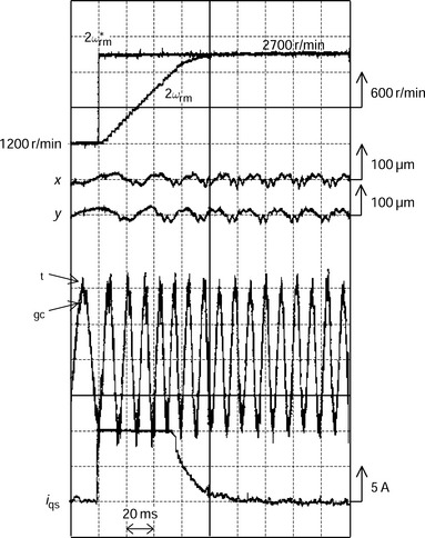
In the radial displacement waveforms, there is no serious fluctuation when the airgap-oriented vector controller is employed. Only a small variation in x and y, caused by shaft unbalance and mechanical tolerance, is seen. The frequency of these small radial vibrations gradually increases as the speed increases.
The cosinusoidal waveform of airgap flux linkage λgc and detected flux waveform Ψt are also shown. Ψt is detected by a search coil wound around the stator teeth which corresponds to the position of cosinusoidal flux component. If a primitive controller is employed, a phase-shift and amplitude difference is seen in Ψt after 20 ms of the step in speed command. However, good correspondence is seen in this figure. This result indicates that the airgap flux linkage in the actual bearingless induction machine corresponds to the flux command [4].
13.3 Direct type drives
In the previous section an indirect vector controller was described. The indirect vector controller is cost-effective because it does not require flux sensors. However, it does require the machine parameters, which may vary with operational conditions. On the other hand a direct vector controller does not need the machine parameters because the revolving magnetic field is detected by flux sensors. Thus the direct vector controller is robust with respect to temperature variation. Some recent direct vector controllers do not need flux sensors, with the fluxes being estimated from the terminal voltage and line current, as well as the machine parameters; and a combination of indirect and direct control has also been recently proposed.
In the bearingless induction motor, instantaneous rotational position and amplitude of the airgap flux linkage vector are required for the radial position controller. These values are given by the motor vector controller described in the previous section. In this section, the airgap flux linkage is detected by flux sensors and sampling of the terminal voltage and current. There are advantages to direct detection of airgap flux linkage in bearingless induction motor drives:
(a) The motor driver can be operated independently of the radial position controller so that the motor controller does not need to provide airgap flux linkage information.
(b) Hence the motor driver can be a general-purpose inverter, operated with a constant V/f profile. These inverters are mass produced so that the cost is low.
(c) The motor windings can be supplied from a commercial power system with constant voltage and frequency.
In this section two types of direct flux detection are introduced.
13.3.1 Search coil method
Figure 13.9 shows a cross section of the stator iron core and search coil arrangement. For the 4-pole and 2-pole windings, one phase is shown. The 4-pole conductor phase-belts are located at the bottom of two adjacent stator slots and are distributed in four sections. The other stator slots will contain the v- and w-phases; the 4-pole winding is single layer, so there will only be one coil side per slot and phase coils will not share slots. The 2-pole conductor phase-belts are located at the top of four successive slots distributed in two bands. The individual 4-pole and 2-pole conductor arrangements are similar to single-layer windings found in conventional induction motors.
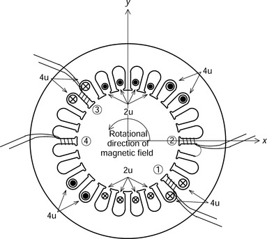
Four search coils are wound around different stator teeth and numbered 1 to 4. Let us suppose that the 4-pole windings are excited by a symmetrical 3-phase current to generate a revolving magnetic field. The 4u-conductors are excited by a cosinusoidal current so that search coil 2 detects the cosinusoidal flux component and search coil 1 detects the sinusoidal component. Coils 3 and 4 are placed on opposite stator teeth with respect to search coils 1 and 2. These additional search coils are needed to cancel the influence of the 2-pole suspension force flux component as shown in the next figure. Note that Hall probes can also be installed to detect airgap fluxes instead of search coils.
Figure 13.10 shows the detected waveforms for search coil fluxes Ψ1 and Ψ2. The voltage induced at the search coil terminals are integrated by an RC integrator circuit. The flux command λgc in the indirect controller is also shown. No suspension force is generated in the upper trace, but 2.6 kgf is generated in the middle and the lower traces. From these figures the following observations can be made:
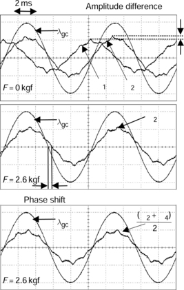
(a) The amplitudes of Ψ1 and Ψ2 are not exactly equal, with Ψ2 being slightly larger in amplitude.
(b) The phases of λgc and Ψ2 agree only when no suspension force is generated.
(c) λgc is in phase with the average of Ψ2 and Ψ4 even though a suspension force is generated.
When a suspension force is generated, both 4-pole and 2-pole revolving magnetic fields are generated so that the search coils detect the sum of these magnetic fields. However, the average of the output of two opposite search coils eliminates the 2-pole revolving magnetic field so that the averaged search coil voltage is independent of suspension force as noted in (c).
The amplitude difference noted in (a) is caused by space harmonics in the MMF distribution. The calculation is quite involved and MMF harmonics should be considered for the 24-slot stator; however, simply multiplying constants will provide compensation [10,11].
Figure 13.11 shows a system block diagram for direct flux detection in a bearingless induction motor drive. The sinusoidal and cosinusoidal flux components are obtained from
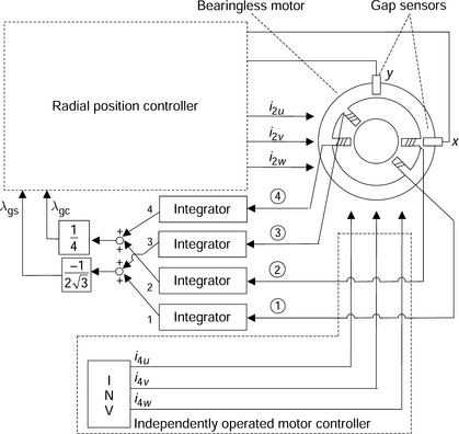
Note that the constants ![]() and 1/4 depend on the conductor arrangement and number of stator slots. One practical method is to adjust the detector gains after the integrator outputs are added. The detected flux components are used in the modulation block of the radial position controller. An open-loop inverter is connected to the motor winding terminals to drive the motor and it operates independently. In experiments, a step speed acceleration using a square-waveform inverter supply was performed and it was found that the magnetic suspension was stable during the acceleration [5].
and 1/4 depend on the conductor arrangement and number of stator slots. One practical method is to adjust the detector gains after the integrator outputs are added. The detected flux components are used in the modulation block of the radial position controller. An open-loop inverter is connected to the motor winding terminals to drive the motor and it operates independently. In experiments, a step speed acceleration using a square-waveform inverter supply was performed and it was found that the magnetic suspension was stable during the acceleration [5].
13.3.2 Detection from line voltage and current
Figure 13.12 shows a block diagram of another method for detecting the airgap flux linkage vector. The airgap vector is calculated from the voltage and current at the motor winding terminals so that search coils are not required. The stator flux linkage vector [λabs] is in a 2-phase coordinate system and obtained by the integration of the 2-phase voltage [vabs] and subtracting the stator resistance voltage drop, i.e., the product of stator resistance Rs and 2-phase current vector [iabs] so that
The rotor flux linkage vector [λabr] in 2-phase coordinates is
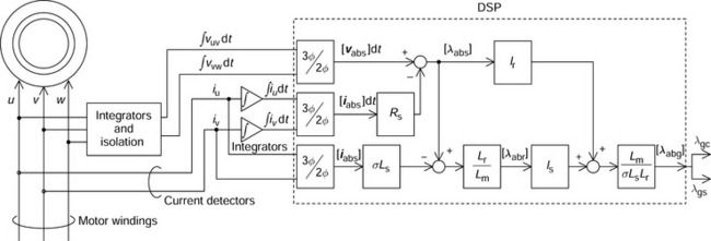
where Lr and Ls are the rotor and stator self-inductances. These are the sum of mutual inductance Lm and the respective rotor or stator leakage inductances. The leakage coefficient σ is given by
so that the airgap flux linkage vector is obtained from the stator and rotor flux linkage vectors
where ls and lr are stator and rotor leakage inductances. The components of the airgap flux linkage vectors are cosinusoidal and sinusoidal.
In the figure, the line-to-line voltages are integrated and isolated and then transformed into 2-phase coordinates to calculate the integral of the voltage vector. The line currents are detected so that the current vector can be calculated. The above equations are calculated to obtain the airgap flux linkage vector. The outputs λgc and λgs are fed to the modulation block in the radial position controller. These blocks can be processed using a digital signal processor. To verify the control strategy a detection and sampling system was also constructed and tested and successful magnetic suspension, with an open-loop inverter, was confirmed [12].
Note that the sensitivity of parameter Rs cannot be neglected at low speed. The stator resistance varies significantly with temperature and this may cause an error in the detected airgap flux linkage vector. It should also be noted that the amplitude of airgap flux may not always be constant; for example, in some control strategies the rotor flux amplitude rather than the total airgap flux is kept constant. In this case the airgap flux linkage vector should be calculated or detected for the modulation block. How this is done is described in the following section.
13.3.3 Modulation block suspension current commands
In the previous section, which described indirect vector controllers, the amplitude of the airgap flux linkage was kept constant. However, in practical applications, the excitation level may change depending on the operational conditions so that the detected airgap amplitude may vary. If this is the case, the suspension current calculation in the modulation block can be modified [13]. In a squirrel cage induction motor, the relationship between the suspension forces and currents can be written as [6]
where i4gd and i4gq are the airgap flux linkage component currents in the d- and q-axes for the 4-pole winding and i2gd and i2gq are the corresponding 2-pole winding currents. These currents are dc under steady-state conditions and this equation indicates that a suspension force is generated by the interaction of the 2-pole and 4-pole airgap flux linkage currents. Let us assume a 4-pole motor with a pole-specific rotor so that i2gd and i2gq are simply given as
Let us also assume that the airgap flux linkage is aligned with the d-axis so that i4gq = 0. The product of M′ and i4gd is defined as λ′g. Hence the suspension forces are given by
The radial winding current commands are generated from the inversion of the matrix in the above equation
The equations (13.17) and (13.18) provide some important points about the control of the bearingless induction motor:
(a) In (13.17) the suspension forces are proportional to λ′g, which is the product of M′ and airgap flux linkage current i4gd. M′ is the displacement derivative of mutual inductance between motor and suspension windings. Let us consider λg without the derivative; λg is the flux linkage of the suspension winding due to the airgap flux and it is almost proportional to the rotor displacement. It is easily obtained from inductance measurements. λ′g is the slope of the flux linkage characteristic of the suspension winding with respect to the rotor displacement so that λ′g is proportional to λg.
(b) The cosine and sine functions originate from the rotational coordinate transformation of the current. The angular position is 2ω4t (aligned with the d-axis with t = 0) so that λgcos4ω4t and λgsin4ω4t indicate perpendicular components of the airgap flux linkage.
(c) From points (a) and (b) the radial forces are given by a matrix product of the cosine and sine airgap flux components and the suspension winding currents.
(d) In a controller, the suspension currents can be calculated by detection or by feed-forward commands of the airgap flux in two perpendicular axes.
13.4 Two-pole motor drive
Since the induction motor has a cylindrical rotor, either of the 4-pole and 2-pole windings can be assigned as the motor drive winding. In this section a comparison of winding assignment is made.
A comparison of a machine with a 2-pole motor drive with 4-pole suspension winding with respect to the 4-pole motor winding arrangement is summarized below:
(a) Better transfer function of the suspension force to the currents when using a squirrel cage rotor.
(b) Reduced VA requirement at suspension force winding terminals.
(c) Self-excitation of the suspension force winding terminals with a squirrel cage rotor.
(d) Increased layers of end-ring segments in the pole-specific rotor.
Characteristic (a) is an advantage of the 2-pole motor drive. The transfer function of the suspension force to the suspension force winding current, shown in the first section of this chapter, has a phase-lag and amplitude reduction caused by the rotor short circuit. The phase-lag causes interference of the two perpendicular suspension forces and a decrease in phase margin of the radial position controller. Calculation of the transfer function of the 4-pole suspension winding should be based on an instantaneous flux representation rather than the equivalent circuit. The analysis should start from the flux linkage to current relationships, with a12 × 12 matrix to determine the flux linkages and currents of the rotor and both 3-phase stator winding sets, including a consideration of the radial rotor displacement [6]. The matrix relationship is simplified by a 3-phase to 2-phase transformation which results in an 8 × 8 matrix and then the stored magnetic energy is calculated. Suspension forces are derived from the partial derivatives of the stored magnetic energy so that the suspension force is a product of the airgap flux currents in the 2-pole and 4-pole windings as well as a derivative of mutual inductance with respect to a radial displacement. A state-space equation with eight states, i.e., 4-pole and 2-pole rotor and stator flux linkages in two perpendicular axes, is set up and the airgap flux currents and suspension forces are calculated. The suspension force and current relationship is derived through simulation to obtain the frequency characteristics. For low-power bearingless machines, squirrel cage circuits are acceptable because of the short time constant.
Characteristic (b) is also an advantage of the 2-pole motor drive. The frequency of a 2-pole motor drive is about a half of the 4-pole motor drive. In addition, the frequency of the suspension force winding current in the 2-pole motor is halved for static suspension force generation because the suspension current frequency is equal to the motor current frequency. Since the current frequency is halved, only half the terminal voltage is required so that the VA requirement, i.e., the product of voltage and current, is reduced.
Characteristic (c) can be an advantage in some applications. In generating a static suspension force for suspending the shaft weight, ω4 and ω2 are the same value. In a 2-pole motor drive, ω2 is nearly equal to the shaft speed ωrm so that the slip s4 is almost −0.5. A negative slip indicates generator operation, hence real power is generated. The output power is sufficient to supply the winding copper losses and inverter losses if the speed and suspension force are high enough so that the suspension power is provided by self-excitation [7].
An effective application can be vibration suppression at high speeds. A shaft is suspended by external bearings. As the speed increases, self-excitation occurs. Then a damping force is generated by the bearingless induction rotor which is located at the centre of the shaft length so that the shaft vibration is suppressed effectively.
Characteristic (d) is a disadvantage of the 2-pole motor drive. As shown in the first section of this chapter, a pole-specific short circuit can be constructed for better suspension force generation. The number of end-ring segments at each end is equal to the number of rotor bars. For example, 16 rotor bars require eight end-ring segment layers at each end. For the 4-pole motor drive, only 4 coil end-ring layers are necessary. Reduction of end-ring segment layers is possible if more than two rotor bars are connected to an end-ring segment. However, the radial force transfer characteristics are inferior because of the rotor short circuits between adjacent bars which produce non-pole-specific current [1].
References
[1] Chiba, A., Miyatake, R., Hara, S., Fukao, T., “Transfer Characteristics of Radial Force of Induction-Type Bearingless Motors with Four-Pole Rotor Circuits”. International Symposium on Magnetic Bearings ’96, Kanazawa (ISMB ’96), 1996:319–325. [August].
[2] Chiba, A., Fukao, T., “Optimal Design of Rotor Circuits in Induction-Type Bearingless Motors”. IEEE Transactions on Magnetics, Vol. 34, No. 4, 1998:2108–2110. [July].
[3] Chiba, A., Furuichi, R., Aikawa, Y., Shimada, K., Takamoto, Y., Fukao, T., “Stable Operation of Induction-Type Bearingless Motors Under Loaded Conditions”. IEEE Transactions on Industry Applications, Vol. 33, No. 4, 1997:919–924. [July/August].
[4] Chiba, A., Yoshida, K., Fukao, T., “Transient Response of Revolving Magnetic Field in Induction-Type Bearingless Motors with Secondary Resistance Variations”. International Symposium on Magnetic Bearings (ISMB ’98), Boston, USA, 1998:461–475. [August 7,].
[5] Yasuda, K., Kuwajima, T., Chiba, A., Fukao, T., “A Proposed Controller for Bearingless Induction Drives with Search Coils Wound Around Stator Teeth”. Proceedings of the Maglev 2000 June 7–10, 2000:435–440. [Rio de Janeiro, Brazil].
[6] Fujishiro, T., Hanawa, R., Sakata, Y., Chiba, A., Fukao, T., “An Analysis of an Induction Bearingless Motor with a Squirrel Cage Rotor”. Proceedings of the 8th International Symposium on Magnetic Bearing, 2002. ISMB 8 August 2002 at Mito, Japan.
[7] A. Chiba, M. Yamashita, K. Kobayashi and T. Fukao, “Principles of Self-excitation at Radial Force Winding Terminals in Bearingless Induction Motors with a Squirrel Cage Rotor”, IEEE IAS 2000 Annual Meeting, Rome 00CH37129, pp. 235–240.
[8] A. Chiba, M. Yamashita, K. Kobayashi and T. Fukao, “Principles of Self-excitation at Radial Force Winding Terminals in Bearingless Induction Motors with a Squirrel Cage Rotor”, IEEE IAS 2000 Annual Meeting, Rome 00CH37129, pp. 235–240.
[9] Novotny, D.W., Lipo, T.A., “Vector Control and Dynamics of AC Drives”. Oxford Science Publications, 1996.
[10] Kiryu, K., Chiba, A., Fukao, T., “A Radial Force Estimation with Search Coil Fluxes in a Bearingless Induction Motor Driven by Multi Inverters”. European Power Electronics Conference (EPE 2001) CDROM, 2001. [August Graz, Austria, 11 pages].
[11] Kiryu, K., Chiba, A., Fukao, T., “A Radial Force Detection and Feedback Effects on Bearingless Motors”. IEEE Industry Applications Conference, September 30, 2001. [at Chicago IEEE01CH37248C 0-7803-7114-3/01, 6 pages].
[12] K. Yasuda, T. Kuwajima, A. Chiba and T. Fukao, “A Feedback Controller With Airgap Flux Estimation in Induction Type Bearingless Motors”, 2000 National Convention Record IEE Japan 5–123, March 24, 2000 at Tokyo Institute of Technology, pp. 2090–2091 (in Japanese).
[13] Kuwajima, T., Yasuda, K., Chiba, A., Fukao, T., “Decoupling Control of the Radial Forces with Gap Flux Estimation”. IEEJ Technical Meetings on Static Power Converters, SPC-00-44 June 30, 2000:41–46.at Mie University (in Japanese)