
Synchronous reluctance bearingless motors
Since there are no rotor windings or permanent magnets the synchronous reluctance machine can be used for high-speed applications including operation at high temperature. Synchronous reluctance machines are also inherently low cost (for the same reasons), which makes them attractive in many applications.
In this chapter, synchronous reluctance bearingless motors are introduced and their principles, physical structure and a compensator structure are described. In these machines, the unbalanced magnetic pull due to rotor eccentricity has to be considered in order to realize stable and robust magnetic suspension. Hence compensation of the suspension force (which is proportional to the shaft displacement) is necessary. The described controller is also applicable to other bearingless motors which have a considerable force-displacement factor and require unbalanced magnetic pull compensation.
12.1 Torque characteristics
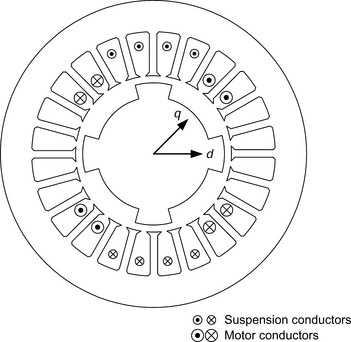
Figure 12.1 shows the cross section of a 4-pole synchronous reluctance bearingless motor with only the u-phase motor and suspension windings shown (of a 3-phase winding). Typically, both the rotor and the stator are constructed from laminated silicon steel and the stator is identical with that of a bearingless induction motor or a permanent magnet motor, i.e., the inner surface of the stator is cylindrical and the stator windings have general sinusoidal distribution. The stator has both n-pole motor windings and (n ± 2)-pole suspension windings. Because the rotor has salient poles, reluctance torque is produced when the 4-pole motor winding is excited and there is a phase angle. This is the sole source of torque in this type of motor so that in order to produce torque effectively with low current, the airgap should be designed to be as small as possible and a high saliency ratio is necessary to achieve high torque and power-factor.
12.1.2 Voltage and current
The terminal voltages for the synchronous reluctance bearingless motor, as derived in Chapter 7, are
Since these motors do not have permanent magnets, d-axis excitation is provided only by the d-axis component of the motor winding current. Depending on the saliency of the rotor, the d-axis inductance Ld should be much higher than q-axis inductance Lq and the ratio of Ld/Lq is defined as the saliency ratio.
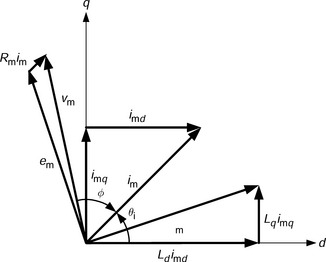
Figure 12.2 shows a phasor diagram for a synchronous reluctance motor having a saliency ratio Ld/Lq of 3, with the condition that the motor d-axis current is equal to the motor q-axis current. A ratio of 3 is typical for the type of rotor shown in Figure 12.1. In the phasor diagram, Ψm is the motor winding flux linkage, im is the motor current and νm is the terminal voltage. Since d-axis current is required for excitation, the phase angle φ between current and terminal voltage is rather large. Hence typical synchronous reluctance motors do not have high power-factor. Another way to consider the phasor diagram (to assess the reluctance torque) is to neglect the winding resistance and put the current on the d-axis and then on the q-axis. In both cases the phase angle between the voltage and current will be 90 deg which means there is no input power and hence no torque. When the current is not on these axes then the difference between Ld and Lq leads to a phase angle which is less than 90 deg which means there is input power and hence a reluctance torque (or output power if the angle is greater than 90 deg and the machine is generating). For a certain current magnitude the peak torque will occur when the motor winding current is at 45 deg electrical deg.
It is possible to increase the saliency ratio and the power-factor by some modifications of the rotor. For example, a high saliency ratio can be obtained with flux barriers in the rotor.
12.1.3 Torque
The torque of synchronous reluctance machines can be written as:
where pp is the number of pole-pairs of the motor windings. From (12.2), the torque can be controlled with both d-axis and q-axis motor winding current or, put another way, the magnitude and phase angle of the motor current. Hence the current phase angle θi is defined by
There are several methods for regulating the motor currents [1,2]. Suppose that current phase angle is regulated while the magnitude of the current is kept constant. In this operation, the copper losses are constant and the maximum torque is obtained at a phase angle θi = π/4. Hence, the copper losses are a minimum at this phase angle for any torque. Next, suppose that the magnitude of the flux linkage is kept constant so that both the d- and q-axis currents are regulated to satisfy the following constraint:
In this operating mode, the iron losses due to the motor flux are almost constant and the maximum torque is obtained at θi = arctan (Ld/Lq). Hence the iron losses are minimized at this phase angle for any torque. Moreover, this phase angle is also optimal for a fast torque response under a limited terminal voltage condition. Therefore the optimal phase angle for minimizing the motor losses is between the above phase angles so that
For correct operation the phase angle should be determined by taking into account these losses, as well as the terminal voltage, the rotational speed and any variations of the motor constants. Torque can be regulated using the current amplitude.
12.2 Radial force characteristics
The synchronous reluctance bearingless motor produces a suspension force by the superposition of the n-pole motor flux and the (n ± 2)-pole suspension flux. If a bearingless motor has a 2-pole suspension winding in addition to the 4-pole motor winding then the suspension force can be derived (as in equations (7.20) and (7.21))
The radial forces F1x and F1y can be regulated using the suspension currents isa and isb so that the direction of the suspension force varies with both the rotor rotational angle and the ratio (M′dimd)/(M′qimq). The magnitude of the force is also a function of motor currents imd and imq. Hence the suspension currents must be regulated in accordance with (12.6) in order to produce the required radial force.
12.2.2 Unbalanced magnetic pull
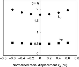
Figure 12.3 shows the measured d- and q-axis inductances for the motor windings with respect to the normalized rotor radial displacement. These inductances can be derived from self and mutual inductances for a 2- or 3-phase stator winding. If we approximate the variation of the d- and q-axis inductances to first-order equations of radial displacements x and y from the centre so that these inductances are then constant, then no radial force due to rotor eccentricity would be generated according to the analysis, as described in Chapter 6 [3,4]. However, due to the small airgap of the synchronous reluctance machine, the inductances vary significantly with rotor displacement (whereas in thick permanent magnet machines they do not); hence the unbalanced magnetic pull should not be neglected. Therefore let us assume that the variations of the inductances are second-order equations [5] so that
The magnetic energy stored in the d- and q-axis inductances varies in accordance with the rotor displacement. From the expressions of inductance in (12.7) and (12.8), the radial forces can be derived, and it is found that they are proportional to the radial displacement, where
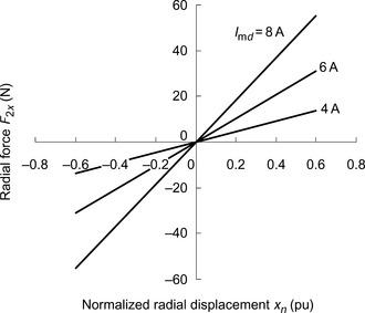
Figure 12.4 shows the resultant unbalanced magnetic pull. Since the inductances increase with rotor displacement, the generated unbalanced magnetic pull is in the displaced direction (where the airgap flux is most concentrated), so that the displacement-originated force is proportional to the radial displacement. A proportional gain controller can regulate the suspension currents to produce a radial force which is also proportional to the radial displacement; however, this force acts towards the stator centre, i.e., in the opposite direction of the unbalanced magnetic pull. Thus, in a feedback controller, the proportional gain Kp can be modified to become
as a result of the unbalanced magnetic pull. The influence on the suspension system can be seen in the frequency range where the proportional gain is dominant.
A test machine, having a coefficient of unbalanced magnetic pull ad = 4000 Nm−1 A2 has a motor d-axis current imd = 8 A. The proportional gain of the suspension controller Kp = 5 × 10⁵N/m, including a sensor gain. Derive the decrease in loop gain (in dB) at the frequency where the proportional gain is dominant. The decrease is caused by an unbalanced magnetic pull.
The unbalanced magnetic pull per meter of radial displacement is 4000 × 82 N/m. The sum of proportional gain and unbalanced magnetic pull is
Therefore, the difference in loop gain becomes
Hence the loop gain is decreased by 6.2 dB in the middle frequency range due to the unbalanced magnetic pull caused by the exciting current.
12.3 Drive systems
Synchronous reluctance bearingless motors have both a motor control system and a suspension control system. These have dependent relationships with each other due to the characteristics of the radial force. In this section, a drive system for a synchronous reluctance bearingless motor with a 4-pole motor winding and 2-pole suspension winding is introduced.
12.3.1 Suspension control system
Figure 12.5 shows the suspension control system where the radial positions are detected and compared with the references. These positions are also used for the calculation and cancellation of the unbalanced magnetic pull; this is done by subtracting the calculated unbalanced magnetic pulls F*2x and F*2y from the outputs of the suspension controllers. Hence, the suspension controllers can be designed without considering the unbalanced magnetic pull. Block A in Figure 12.5 converts the suspension force commands into appropriate suspension current commands using the following equation [6]:
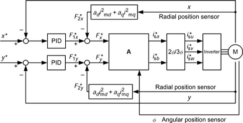

which is derived from (12.6). If the motor has 3-phase windings, the 2-phase current commands should be transformed into 3-phase values using the block 2φ/3φ where
12.3.2 Motor control system
Figure 12.6 shows the motor control system. The rotor angular position is required for coordinate transformation from rotational to stationary coordinates and the derivative of the angular position is required to maintain the rotational speed. A torque command T*r is generated from the speed error in the speed regulator, which is a proportional-integral (PI) controller. In block B, the d- and q-axis current commands are determined from the torque command using

which is derived from (12.2). There are several combinations of i*md and i*mq which can produce the desired torque. The d- and q-axis motor current commands are then transformed into stationary coordinates in block dq/ab where
And from this the 2-phase current commands are transformed into 3-phase current commands in block 2φ/3φ so that
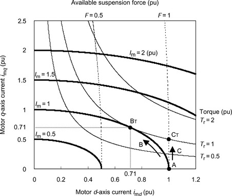
Figure 12.7 shows the available torque and radial force in the motor current plane from a motor where the ratio M′d/M′q is 10. The winding currents, torque and suspension force are normalized values. If the torque of the motor is zero then the q-axis current should be set to zero and the d-axis current imd to 1 in order to produce the maximum radial force F = 1. Hence, operating point A provides the maximum suspension force with no load operation. If the torque current is increased along arrow B to produce torque with the motor current magnitude at the limit, then the available radial force decreases. The maximum torque is achieved at point BT. Another control strategy which increases both the torque and suspension force is to operate along the line indicated by arrow C. Maximum torque is obtained at operating point CT and both the torque and suspension force are 1 pu. The characteristics described by arrows B and C are determined by the combination of i*md and i*mq.
12.3.3 Magnetic saturation
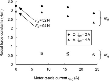
When torque is required, and if the motor current is increased along arrow C in Figure 12.7, then the flux density of the motor increases. Moreover, when suspension force is required, the flux density increases in some parts of the motor [7,8]. This flux density increase may result in magnetic saturation, especially in the stator teeth. Figure 12.8 shows the analysed radial force constants of a test machine at imd = 8 A. The machine has the following dimensions: rotor diameter = 49.2mm, rotor stack length=50.0mm and stator inner diameter = 50.0mm. The maximum flux density in the stator teeth is 0.9T when only d-axis current imd = 8 A is provided. The radial force constants decrease with an increase in torque current and suspension current. It is obvious from (12.6) that these variations of the radial force constants may cause the loop gain to decrease, resulting in force direction variation in the suspension control system. Therefore, the suspension control system performance may be poor when the motor produces high suspension force and torque. To avoid this, the parameters in the suspension control, as described by (12.13), should be calibrated in order to cancel these variations if the motor is operated in the nonlinear region. One solution was described in the previous chapter; the parameter variations are also significant in synchronous reluctance machines. There are several ways to obtain estimates of the parameter variations:
2. Parameter tables obtained by analysis or off-line measurements [9].
3. Approximated equations obtained by analysis or off-line measurements.
12.3.4 Characteristics of a test machine
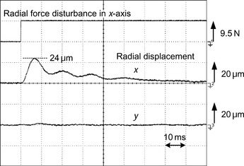
Figure 12.9 shows the radial displacement of a test machine when imd = 6 A and imq = 11 A [5]. A radial step force of 9.5 N is applied to the rotor by adding a step disturbance to the suspension force command. It is shown that the radial positions on the x- and y-axes are stably controlled and that there is no interaction between the two axes even at high torque where there are magnetic saturation conditions. This is because parameters M′d and M′q have been identified and calculated correctly.
Figures 12.10 and 12.11 show the open-loop bode plots for a suspension control system [5]. The results in Figure 12.10 were measured without compensators for the negative displacement-stiffness, i.e., without cancellation of the unbalanced magnetic pulls F*2x and F*2y as shown in Figure 12.5. Due to the variations of unbalanced magnetic pull, the loop gain of the suspension control system decreases with an increase of the d-axis current. On the other hand, in Figure 12.11, the results were obtained with the negative-displacement-stiffness compensators, and here it is shown that the loop gain of the system is successfully kept constant for all d-axis current values.
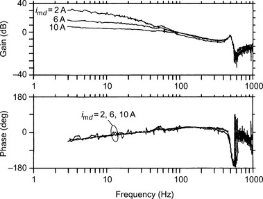
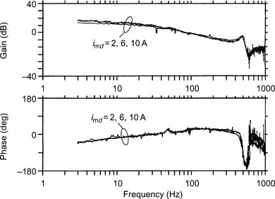
If the d-axis current is changed during operation, the negative-displacement-stiffness compensator is necessary to obtain the constant characteristics of the suspension control system for any d-axis current. It is advantageous to compensate for the unbalanced magnetic pull even if the motor is operated with a constant d-axis current in order to design the suspension controller.
References
[1] Fukao, T., Chiba, A., Matsui, M., “Test Results on a Super High Speed Amorphous Iron Reluctance Motor”. IEEE Transactions on IA, Vol. 25, No. 1, 1989:119–125.
[2] Chiba, A., Fukao, T., “A closed-Loop Operation of Super High-Speed Reluctance Motor for Quick Response”. IEEE Transactions on IA, Vol. 28, No. 3, 1992:600–606.
[3] Chiba, A., Chida, K., Fukao, T., “Principles and Characteristics of a Reluctance Motor with Windings of Magnetic Bearing”. IEEJ Proc. IPEC-Tokyo 1990 (International Power Electronics Conf.), 1990:919–926.
[4] Chiba, A., Rahman, M.A., Fukao, T., “Radial Force in a Bearingless Reluctance Motor”. IEEE Transactions on IA, Vol. 27, No. 2, 1991:786–790.
[5] Ichikawa, O., Michioka, C., Chiba, A., Fukao, T., “An Analysis of Radial Forces and a Rotor Position Control Method of Reluctance Type Bearingless Motors”. Transactions of IEE Japan, Vol. 117–D, No. 9, 1997:1123–1131.(in Japanese)
[6] Ichikawa, O., Michioka, C., Chiba, A., Fukao, T., “A Decoupling Control Method of Radial Rotor Positions in Synchronous Reluctance Type Bearingless Motors”. IEEJ Proc. IPEC-Yokohama 1995 (International Power Electronics Conf.), 1995:346–351.
[7] Chiba, A., Hanazawa, M., Fukao, T., Rahman, M.A., “Effects of Magnetic Saturation on Radial Forces of Bearingless Synchronous Reluctance Motors”. IEEE Transactions on IAS, Vol. 32, No. 2, 1996:354–362.
[8] Michioka, C., Sakamoto, T., Ichikawa, O., Chiba, A., Fukao, T., “A Decoupling Control Method of Reluctance-Type Bearingless Motors Considering Magnetic Saturation”. IEEE Transactions on IAS, Vol. 32, No. 5, 1996:1204–1210.
[9] Hertel, L., Hofmann, W., “Magnetic Couplings in a Bearingless Reluctance Machine”. Proc. ICEM 2000 (International Conf. on Electrical Machines), Vol. 3, 2000:1776–1780.