
Mechanical structure and position regulation
There are two main mechanical arrangements for rotational electric machines – radial gap machines and axial gap machines. Although most of the proposed bearingless motors are radial gap machines it is possible to construct axial flux types of this machine. In this chapter, different mechanical structures for the bearingless motor are introduced and the axial-gap type of bearingless motor is described in detail. This actively regulates the thrust and inclination movements of the rotor. One aspect highlighted is that radial vibration is shown to be suppressed with a small rotor incline at the critical speeds.
17.1 Mechanical structure
17.1.1 Radial gap bearingless motor
Figure 17.1 shows the typical structure of a radial gap motor. All the airgap flux components flow in the radial direction. One of the advantages of the radial gap motor is that the normal forces exerted on the rotor surface cancel each other out if the rotor is positioned at the stator centre.
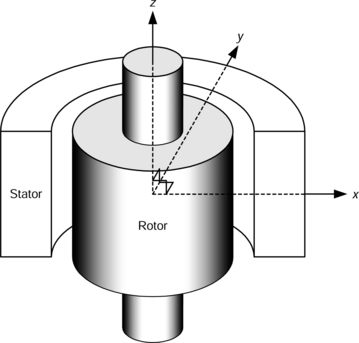
Some modifications of the rotor and stator structures are possible as described in Chapter 1. For example, two tandem radial gap bearingless motor units can regulate four radial degrees of freedom. Radial gap machines also produce a small axial force along the z-axis due to the rotor tending to centre itself on the axial centre of the stator – this force is due mainly to the main motor flux. If the rotor is allowed to have a small amount of axial movement then this axial force may be sufficient for the z-axis suspension. However, if precise z-axis positioning is needed then an additional magnetic thrust bearing is required.
17.1.2 Axial gap bearingless motor
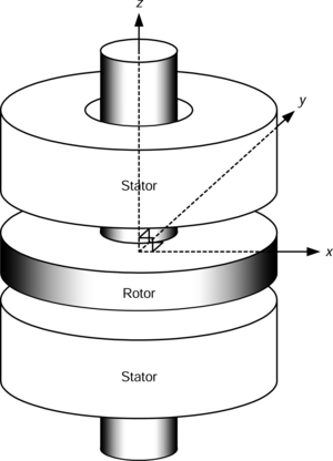
Figure 17.2 shows the typical structure of an axial-gap motor. All the flux in the airgap flows in the axial or z direction. Most of the flux is produced to generate the motor torque and this also generates a large axial force between the rotor and stator which is not cancelled out as in the radial-flux machine. However, by arranging two axial gap machines as shown in Figure 17.2, it is possible to cancel the axial forces. The axial position of the rotor can be maintained with the motor current. Inclination torques (i.e., torques that do not act around the normal z-axis of the motor) around the x- and y-axes (in the rotor disk plane) can be generated by an unbalanced airgap flux distribution caused by injecting suspension currents. These torques are used to keep the rotor disk position at the horizontal and axial centre (or any angle of incline that is required). Therefore axial and rotational positioning is realized. There also exists a small radial force, similar to the axial force in a radial-gap bearingless motor, which keeps the rotor at the radial centre.
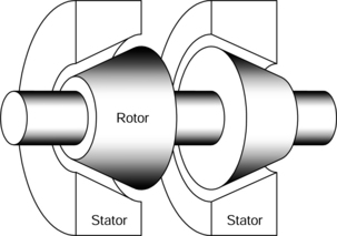
Another possible structure is shown in Figure 17.3 where the radial and axial magnetic suspensions are combined. Radial positioning of the rotor can be controlled by the superposition of the motor and suspension fluxes while the axial position of the rotor can be controlled by the motor flux. Therefore a magnetic thrust bearing is not necessary.
17.2 Axial gap bearingless motors
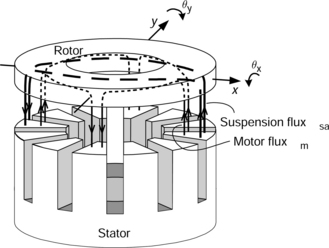
Figure 17.4 shows an example of an axial-gap bearingless motor. A rotor disk between the two stators is magnetically suspended without mechanical contact. If a wheel is attached, either outside or inside the rotor, then a compact pump can be realized. Permanent magnets in a 4-pole arrangement are mounted on the upper surface of the disk rotor producing, in conjunction with the upper stator, a permanent magnet motor. Four salient poles are located on the lower surface so that a synchronous reluctance motor structure is produced in conjunction with the lower stator. The stator of the synchronous reluctance motor has both motor windings and suspension windings located in slots.
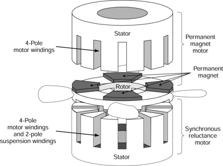
Figure 17.5 shows the main flux paths of the synchronous reluctance motor. All the airgap flux is assumed to flow in the axial direction producing a large axial force. By superimposing the (n ± 2)-pole suspension flux on the n-pole motor flux, the airgap flux density becomes unbalanced and an inclination torque is produced.
The axial position and the incline of the rotor have to be regulated for successful magnetic suspension. The axial position of the rotor can be maintained by the reluctance motor currents while the incline of the rotor around x- and y-axes can be maintained by the synchronous reluctance motor suspension currents. The radial position is passively stable due to the centring force caused by flux in both motors.
17.2.2 Axial position regulation
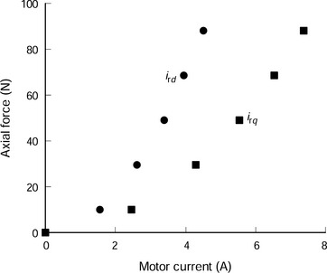
The permanent magnets on the rotor surface produce an axial force in the upward direction. On the other hand, the winding currents of the synchronous reluctance motor produce an adjustable axial force in the opposite (downward) direction, and the axial position of the rotor can be controlled with the synchronous motor currents. Figure 17.6 shows the axial forces generated by the d- and q-axis reluctance motor currents ird and irq. These axial forces were measured in a test machine with an airgap length of 0.48 mm and a stator outer diameter of 120 mm for the synchronous reluctance motor. Both the d- and q-axis currents produce axial force [1] which can be written as
The q-axis reluctance motor current irq is injected to produce a reluctance torque where
Therefore, the motor current commands i*rd and i*rq should be determined using (17.1) and (17.2). For zero torque, ird is maximum and irq = 0. If torque is required then the d-axis reluctance motor current should be decreased as the q-axis reluctance motor current is increased in order to produce constant axial force. From (17.1) and (17.2), the torque can be written in terms of the axial force and q-axis current [2] where
which has a maximum value of
It is obvious that the q-axis reluctance motor current should be in the range
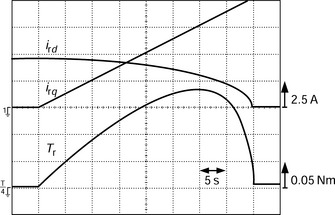
Figure 17.7 shows the measured torque when a constant axial force of 62.5 N is required to maintain the axial position of the rotor. This illustrates the increase of the q-axis current and the decrease of the d-axis current as the torque increases to the maximum point. The torque response of the synchronous reluctance motor should be determined by taking this restriction into account. Note that the permanent magnet motor can produce significant torque without this restriction since axial force is generated without any motor winding current and only q-axis current is required for torque production.
17.2.3 Inclination control
If an (n ± 2)-pole suspension flux is superimposed on the n-pole motor flux then the flux distribution in the airgap is unbalanced and an inclination torque is generated on the rotor. This inclination torque enables the control of rotor angular positions around x- and y-axes. For example, the 2-pole suspension flux Ψsa and the 4-pole motor flux Ψm are superimposed as shown in Figure 17.5. The flux density is increased in the right-hand side airgap and decreased in the left-hand side airgap. This unbalance of flux distribution produces a clockwise inclination torque around the y-axis. Hence, the inclination torques around x- and y-axes can be written in a similar fashion to the radial forces in a radial-gap synchronous reluctance bearingless motor as described in Chapter 12:
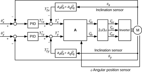
Figure 17.8 shows a block diagram of a rotor inclination control system. The position feedback for the incline of the rotor is obtained from the difference in measurements from a pair of axial-position sensors. Torque commands T*1x and T*1y are calculated from the inclination angular positions around each radial axis which allows the cancellation of the displacement-originated torques T*2x and T*2y. The torque commands T*x and T*y are transformed into suspension current commands in block A using (17.5) so that:
17.2.4 Radial damping control
Radial positioning of the rotor is passively stable without an additional magnetic bearing due to the radial centring force. However, continuous vibrations can occur at a certain rotational speeds because of low damping. It is possible to improve the damping by using rotational torque control of the synchronous reluctance motor and also introducing a small rotor incline [3].
Figure 17.9 shows a mechanism for radial force production which provides improved damping. The rotor is slightly inclined while generating reluctance torque. The flux distribution is unbalanced because of the unsymmetrical airgap length under the salient poles. A flux decrease results in a torque decrease under salient pole 1 and a flux increase results in a torque increase under salient pole 3. While the sum of the torque produced across all the poles is unchanged, the torque unbalance under poles 1 and 3 produces radial force along the negative y-axis. A radial force can be produced in any desired radial direction by adjusting the rotor incline angle. However, the torque unbalance is opposite for the permanent magnet motor side but the large airgap, due to the permanent magnets, results in a negligible torque unbalance compared to the synchronous reluctance motor.
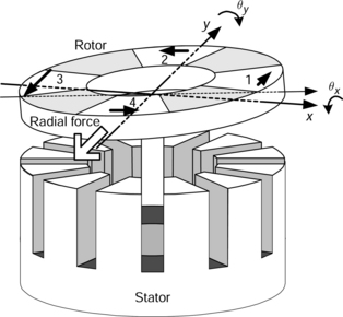
Figure 17.10 shows measured radial forces for the test machine. These radial forces were generated from both the permanent magnet and synchronous reluctance motors. These confirm that a small radial force is produced by a slight incline of the rotor. The magnitude of the radial force is approximately proportional to both the incline angle and the torque current of synchronous reluctance motor so that:
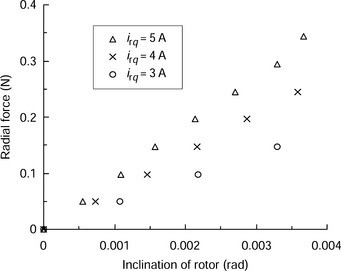
The radial force shown in Figure 17.10 is too small to suspend the 5 kg rotor. However, it is high enough to improve the radial damping. Figure 17.11 shows a block diagram of the radial damping control system. The radial position of the rotor is detected with radial gap sensors. Radial force commands F*x and F*y are produced by the damping regulators, which include derivative controllers and low-pass filters. The incline angle commands are supplied to the inclination control system, as shown in Figure 17.8, producing the radial forces. The bearingless motor produces a radial force to centre the rotor; this force has a force-displacement factor kx, and this can cause a continuous radial vibration at a natural frequency. By controlling the radial damping forces Fx and Fy these vibrations can be suppressed.
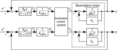
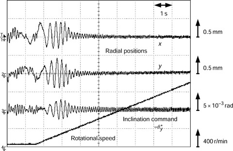
Figure 17.12 shows the experimental results from the radial damping system. During this experiment, the q-axis reluctance motor current was constant at 5 A. Without the damping system, serious radial vibration is seen during the initial acceleration. However, when the damping system is activated the radial vibrations at rotational speed are initially amplified but quickly decay, illustrating the radial damping effect.
17.2.5 Nonlinear characteristics
The control systems of an axial-gap bearingless motor are described above and are based on approximate and simplified models of the bearingless motor. In an actual system, there are motor parameter variations and control system interactions which depend on the operating conditions. In order to operate the motor with acceptable performance some modifications may be required, such as
1. Advanced robust controller design which accounts for parameter variation and gives disturbance suppression [4].
2. Identification and cancellation of parameter variations using an applicable method [5].
In the test machine shown in Figure 17.4, the excitation flux of the permanent magnet motor produces an axial force of 120 N and the rotor weight is 5.0 kg. Suppose that the synchronous reluctance motor has constants of kzd = 3.0 N/A2, kzq = 1.0 N/A2 and kt = 9.0 × 10⁻³ N/A2. Determine the maximum torque produced by the synchronous reluctance motor in the steady-state condition.
If the synchronous reluctance motor produces an axial force Frz along the negative z-axis, the following force equation should be satisfied:
Therefore Frz = 71 N. Substituting this force and the motor constants into the maximum torque condition, derived from (17.3), we obtain the maximum torque as:
References
[1] Li, J.Q., Satoh, T., Ichikawa, O., Michioka, C., Chiba, A., Fukao, T., “The Axial Force of the Shaftless Axial Gap Bearingless Motor”. 1995 National Convention Record I.E.E. Japan, Vol. 5, 1996:5–166.(in Japanese)
[2] Ichikawa, O., Tomita, I., Michioka, C., Chiba, A., Fukao, T., “An Operating Method of the Shaftless Axial-gap Bearingless Motors Considering the Axial Force and the Torque”. The 9th Symposium on Electromagnetics and Dynamics, 1997:525–528.(in Japanese)
[3] Ichikawa, O., Chiba, A., Fukao, T., “Two-axis Vibration Control of Axial Gap Bearingless Motors Using Unbalanced Rotational Torque”. Proc. of the 2000 Japan Industry Applications Society Conf., Vol. 1, 2000:265–266.(in Japanese)
[4] Ichikawa, O., Chiba, A., Fukao, T., “Construction Method of a Position Controller of Axial Gap Bearingless Motors”. IEEJ Proc. of Meeting of Rotating Machinery, RM-98–141, 1998:127–132.(in Japanese)
[5] Saito, F., Ichikawa, O., Takahashi, K., Fukao, T., “Hierarchical Levitation and Rotation Control System of Axial-gap Bearingless Motors”. IEEJ Proc. of Meeting of Semiconductor Power Converter, SPC-99-11, 1999:61–66.(in Japanese)