
Buried permanent magnet bearingless motors
Recently, buried permanent magnet (BPM) motors, often referred to as interior permanent magnet (IPM) motors, have become more commonplace. By employing a field-weakening control, adjustable speed operation can be realized over a wide speed range. In addition, a reluctance torque is generated which increases the motor efficiency. In this chapter, the BPM bearingless motor is introduced. The linear position control strategy employed in cylindrical and inset permanent magnet types of motor is not applicable because partial magnetic saturation occurs in the BPM motor so that the suspension force parameters λ′m, M′q and M′d are influenced by the operating currents. Therefore a successful position control strategy is introduced to solve this problem with off-line and on-line identification methods of parameter variations. The rotor structure and features are described. One of the advantages of this machine is that enhanced radial force can be obtained.
11.1 BPM rotor structures
Figure 11.1(a-c) shows the BPM rotor structures. The advantages of the BPM rotors are as follows:
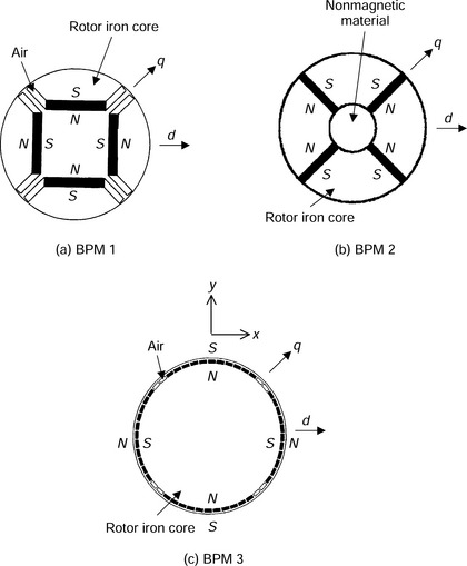
1. The airgap length can be small compared with those in the other types of permanent magnet machines, resulting in an increase in the suspension force for unity suspension winding MMF.
2. The leakage flux goes around the permanent magnets in the rotor core, helping to prevent the irreversible demagnetization of the permanent magnets.
3. Since the permanent magnets are buried in the rotor core, they are protected against centrifugal force at high speed operation.
The structures BPM 1 and BPM 2, shown in Figure 11.1(a,b), are typical interior permanent magnet and spoke types of rotor [1]. The q-axis flux paths are sufficient to increase the saliency ratio. However, these types of rotor are not very suitable for a bearingless motor arrangement. Since the suspension forces are generated by the superimposition of the permanent magnet field and the suspension flux, and the suspension flux goes through the thick permanent magnets and the nonmagnetic material, the suspension forces for a unity suspension winding MMF are small. On the other hand, the rotor structure BPM 3 in Figure 11.1(c) has thin permanent magnets buried just below the rotor surface, which improves radial suspension force generation because of the low permanent magnet magnetic reluctance [2–4]. Therefore, this type of rotor is suitable for a BPM bearingless motor; and the suspension force, the permanent magnet demagnetization and the control strategy for this machine are introduced in this chapter.
11.2 Suspension force for unity current and permanent magnet demagnetization
The BPM 3 rotor shown in Figure 11.1(c) has a ratio of suspension force per unity suspension winding current which is higher than the other types of permanent magnet bearingless motors described in previous chapters. This is due to the small airgap length and the thin permanent magnets. In this section, the suspension force per unity current is compared in order to emphasize that the BPM 3 rotor structure is suitable in radial force generation. The ability to withstand irreversible demagnetization is also described.
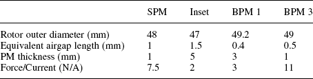
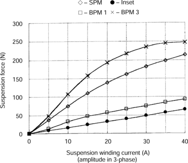
Figure 11.2 shows the suspension forces analysed by the finite element method (FEM) with no torque. The horizontal axis is the amplitude of the suspension winding current in 3-phase coordinates. The analysis is carried out for the SPM and inset types of motor as well as the BPM types 1 and 3 as shown Figure 11.1(a,c). The SPM and inset types are analysed for the structures described in Figures 9.6 and 10.1 and the specifications of these rotors are summarized in Table 11.1. In the SPM and inset types, the equivalent airgap length is large because these motors require a cylindrical cover to fix the permanent magnets to the rotor surface. The stator structure and dimensions are the same for all motors. If the suspension winding current is above 15A, the suspension forces are saturated in the SPM and BPM 3 motors. This is caused by magnetic saturation in the stator teeth. Table 11.1 also shows the suspension force divided by the suspension winding current ratio (F/Is3). F/Is3 for the BPM 1 and inset types are lower due to the thick permanent magnets whereas F/Is3 for BPM 3 is higher due to the small airgap length and thin permanent magnets (F/Is3 for BPM 3 is 5.5 times of that of the inset-type).
As discussed in Chapter 9, permanent magnet demagnetization is an important issue in permanent magnet bearingless motors. The torque and suspension force are restricted by irreversible demagnetization of the permanent magnets. By burying the permanent magnets in the rotor iron core a uniform flux distribution across the magnet surface is obtained so that the problem of partial irreversible demagnetization is eased. As a result, the resistance to irreversible demagnetization of the BPM type of rotor is much better [2].
11.3 Rotor position control strategy
11.3.1 Influence of suspension force parameter variations
The BPM bearingless motor is a salient-pole motor so that, using the control system shown in Figure 7.17, the rotor radial position can be, in principle, stably regulated. However, the suspension force becomes saturated due to partial magnetic saturation caused by the q-axis motor flux since the airgap length is smaller than the SPM and inset types of machine. Hence the suspension force parameters λ′m, M′q and M′d all have load variation. If one assumes that these parameters are constant then the magnetic suspension cannot be stable. Therefore the identification of the parameter variations and the controller integration of these variables are key issues for successful suspension.
Figure 11.3 shows an example of the suspension force analysed by FEM using the BPM machine shown in Table 11.2 and Figure 11.1(c) [3,4]. The suspension windings which generate the MMFs in the x and y directions are Nsa and Nsb. In this analysis, the currents isa and isb are set to 4 and 0 A in these windings. The suspension force in the x direction is almost constant even though the q-axis current is increasing because it is generated by superposition of the suspension flux onto the permanent magnet field. However, the suspension force in the y direction becomes saturated above a q-axis current of 3 A. The y-axis force is caused by the superposition of the suspension flux onto the q-axis motor flux. Since the stator teeth are magnetically saturated above 3 A, the y-axis force likewise saturates.
Table 11.2
| Parameter | Symbol | Value |
| Radius of stator inner surface | r | 25 mm |
| Radius of rotor iron core | R | 24.5 mm |
| PM thickness | lm | 1mm |
| Buried PM depth | ld | 0.5 mm |
| Airgap length | lg | 0.5 mm |
| Rotor axial length | l | 50 mm |
| PM residual flux density | Br | 1T |
| Effective number of turns of Motor winding | n4 | 72.7 turns |
| Suspension winding | n2 | 30.6 turns |
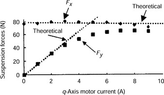
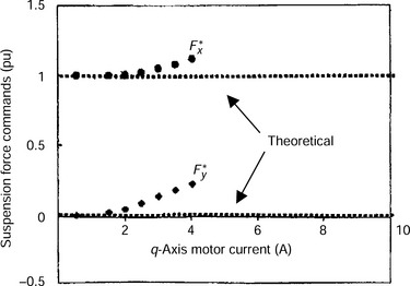
Figure 11.4 shows an example of the measured suspension force commands using constant parameters [3,4]. When the suspension force is generated only in the x direction, the theoretical suspension force commands F*x and F*y are 1 and 0 pu respectively. However, the measured suspension force commands F*x and F*y are not equal to theoretical values when the q-axis motor current is above 2A and the suspension forces have mutual interference in two perpendicular axes. Hence the control system has less damping resulting in a large rotor position fluctuation, and the rotor shaft touches down at high current.
11.3.2 Successful suspension with nonlinear magnetic characteristics
In order to regulate the rotor position accurately, it is important to consider the magnetic saturation caused by the q-axis motor current. The suspension winding currents can only be successfully controlled by considering the parameter variations. Hence it is necessary to express the suspension force parameters as functions of the motor winding currents, and in this section, therefore, an identification method for the suspension force parameters is introduced and an example of suspension force decoupling is described [3,4].
Figure 11.5 shows the variation of the suspension force parameter M′q (as an example of the identification of the suspension force parameters). Initially substituting isq = 0 into (7.16) and solving for M′q yields
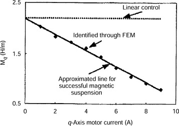
For some values of imq and isd, the suspension force Fj in the j direction is calculated by FEM analysis and then the calculated Fj and the currents imq and isd are substituted into (11.1); Figure 11.5 shows the results. M′q decreases with increasing q-axis motor current and it is therefore necessary to approximate M′q to a line, in this particular machine case, in order to keep the suspension loop gain constant.
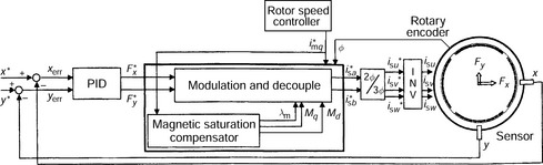
Figure 11.6 shows a successful control system for the BPM type bearingless motor. In the magnetic saturation compensator, M′q is a function of the q-axis current command i*mq. λ′m and M′d can also be functions of I*mq. However, this is not the case in this example; although in some bearingless motor controls, saturation compensators would be required for λ′m and M′d.
In this example, M′q is derived using a series of static FEM analyses. This method is useful for obtaining rough parameter variation estimates off-line. However, FEM results always have a discrepancy from the actual machine parameters because of mechanical tolerances, end effects and other effects. Hence on-line identification is necessary; this can be done using the static force and torque generation tests shown previously in Figure 11.4. The discrepancies of the radial force commands do include radial force parameter errors [3]. Identification is possible up to 4 A, and parameter estimates at higher current values can be obtained by extrapolation for implementation in the controller. More accurate parameter identification is possible if the measured range is extended above 4 A with the parameters again extrapolated.
Examples of some experimental results for the suspension force decoupling, and also the suppression response to a suspension force disturbance and rotor acceleration, are described below [3,4].
Figure 11.7 shows the test results of the suspension force decoupling. The suspension force commands F*x and F*y remain at 1 and 0 pu even though the q-axis motor current is increased.
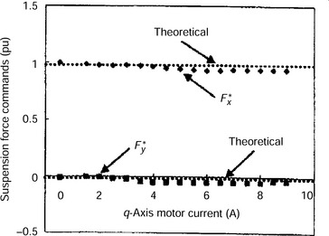
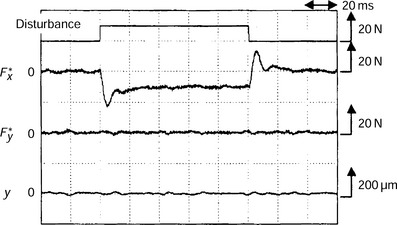
Figure 11.8 shows the suppression response of a x-axis suspension force disturbance. The y-axis suspension force command and the displacement are not influenced due to good decoupling.
Finally, Figure 11.9 shows the rotor acceleration test result. The rotor speed ω is accelerated from 1000 to 2140 r/min using a reference step function. It can be seen that the rotor radial vibrations are suppressed during the rotor acceleration when the motor currents are maximum.
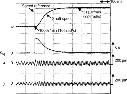
Figures 11.7–11.9 illustrate that the decoupling of the suspension forces in two perpendicular axes can be achieved. Hence the rotor shaft is stably supported even though partial magnetic saturation occurs.
References
[1] Ohishi, T., Okada, Y., Miyamoto, S., “Levitation Control of IPM Type Rotating Motor”. Proceedings of the Fifth International Symposium on Magnetic Bearings, 1996:327–332.
[2] Ooshima, M., Miyazawa, S., Shima, Y., Chiba, A., Nakamura, F., Fukao, T., “Increase in Radial Forces of a Bearingless Motor with Buried Permanent Magnet-Type Rotor”. The 4th International Conference on Movic Proceedings, Vol. 3, 1998:1077–1082.
[3] Fujie, N., Yoshimatsu, R., Chiba, A., Ooshima, M., Rahman, M.A., Fukao, T., “A Decoupling Control Method of Buried Permanent Magnet Bearingless Motors Considering Magnetic Saturation”. Proceedings of IPEC-Tokyo 2000, Vol. 1, 2000:395–400.
[4] Fujie, N., Yoshimatsu, R., Chiba, A., Ooshima, M., Fukao, T., “Influence of Magnetic Saturation on Armature Reaction Flux in Buried Permanent Magnet Type Bearingless Motors”. IEE Japan, The Papers of Technical Meeting on Linear Drives LD-99–153, 1999:33–38.(in Japanese)