
Cylindrical permanent magnet synchronous bearingless motors
The advantages of the permanent magnet type of bearingless motor can be summarized as (1) small size and lightweight, (2) high power-factor and high efficiency and (3) suspension forces that can be generated without excitation current in the main winding. In this chapter, some structures and a control system suitable for cylindrical permanent magnet synchronous bearingless motors are shown. Armature reaction flux is considered in this type of machine in order to regulate the rotor radial position accurately. The rotor radial position control strategy uses this information to calculate the magnitude and the direction of the airgap flux and this is described together with the calculation of the resultant flux from the permanent magnet field excitation and the q-axis flux. It is then shown how the permanent magnet thickness and the airgap length are determined for an optimal design. The influence of the stator winding MMF on the permanent magnet demagnetization is also described. The test results from a prototype of a surface permanent magnet synchronous bearingless motor are included as examples.
9.1 Structure of surface permanent magnet (SPM) rotor
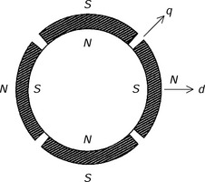
Figure 9.1 shows a typical SPM rotor structure [1–4]. A 4-pole structure is described here as an example. Four permanent magnets are mounted on the iron surface. These are magnetized to produce four magnetic poles. A steel can or carbon-fibre casing usually wraps the permanent magnets in order to fix them to the rotor. It is important to design the permanent magnets to avoid irreversible demagnetization because the suspension flux is superimposed on to the magnetic field and can act in the opposite direction to the magnet polarity. Conversely, however, thin permanent magnets result in more effective radial suspension force generation; this will be discussed in section 9.4.
9.2 Radial suspension force and suspension winding current
In this section, the theoretical relationship between the radial suspension force and the suspension winding current is derived. The permanent magnet MMF is replaced by an equivalent motor winding current component Imp [5,6].
The equivalent 4-pole current ![]() for the motor winding and magnets is represented as
for the motor winding and magnets is represented as
where ![]() denotes a phasor in a 2-phase coordinate system. Imq is the q-axis component, which is the actual motor winding current. The d-axis main winding current should be zero to realize high torque. Imp is the equivalent d-axis component of the permanent magnet MMF and
denotes a phasor in a 2-phase coordinate system. Imq is the q-axis component, which is the actual motor winding current. The d-axis main winding current should be zero to realize high torque. Imp is the equivalent d-axis component of the permanent magnet MMF and ![]() , where E0 is a synchronous internal voltage and Xm is an armature reaction reactance, so that Imp is hereafter referred to as the equivalent permanent magnet current.
, where E0 is a synchronous internal voltage and Xm is an armature reaction reactance, so that Imp is hereafter referred to as the equivalent permanent magnet current.
Stationary and synchronously rotating coordinate systems are drawn in Figure 9.2, where the perpendicular axes in the stationary coordinate are defined as the a- and b-axes. The counter-clockwise direction is defined as the positive angular and rotational direction. In addition, the motor windings Nma and Nmb generate MMFs on the a- and b-axes respectively. Hence the equivalent currents imae and imbe in motor windings Nma and Nmb are represented as
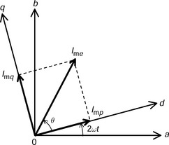
and ω is the mechanical angular speed. The resultant flux of the permanent magnet field excitation and the q-axis winding current can be considered as the 4-pole flux generated by the equivalent currents imae and imbe. The magnitude of the resultant flux is represented by a product of the self-inductance and the current amplitude Ime. The phase-lead mechanical angle θ/2 is in the rotational direction of the revolving field, and it is caused by the armature reaction.
Let us define the currents flowing in the suspension windings Nsa and Nsb in the stator core as isa and isb respectively. The directions of the MMFs generated by the suspension winding currents isa and isb correspond to x- and y-axes respectively. Replacing i4a, i4b, i2a, and i2b, in (6.39) with imae, imbe, isa and isb and substituting (9.2) and (9.3) into imae and imbe produces the radial forces Fx and Fy:
Equation (9.6) shows the relationship between the perpendicular radial suspension force components Fx and Fy and the suspension winding currents isa and isb. Solving (9.6) for isa and isb yields
From (9.4) and (9.5), the amplitude Ime and the phase-lead angle θ of the equivalent current in the motor winding are calculated using the q-axis current Imq. Then the amplitude and phase of the suspension winding currents are obtained using (9.7) in accordance with Ime and θ. Hence, by considering the armature reaction, the cylindrical permanent magnet synchronous bearingless motor can be successfully operated without mutual interference between the radial suspension force components in the two perpendicular axes.
9.3 Equations of voltage and current
In this section, the voltage and current equations of the motor and the suspension windings are derived using the equivalent current in the motor windings shown in the previous section [7].
For a 4-pole machine, the amplitude Vm2 of sinusoidal voltage at the motor winding terminals in a 2-phase coordinate system can be written as
where Lm is the self-inductance of the motor winding. Similarly, the fundamental voltage amplitude Vs2 at the suspension winding terminals in the 2-phase coordinate system is also written as
where Ls is the self-inductance of the suspension winding and Is2 is the fundamental amplitude of the suspension winding current. From (9.7), Is2 can be obtained from
Substituting (9.10) into (9.9) yields
When a cylindrical permanent magnet synchronous bearingless motor operates at 3000 r/min and the q-axis current Imq is 7.8 A, the equivalent permanent magnet current Imp is 20 A and the self-inductances Lm and Ls of motor and suspension windings are 4.5 and 0.7 mH respectively. The derivative of mutual inductance M′ is 0.32 H/m.
(a) Derive the equivalent current amplitude Ime in the motor winding.
(b) When a suspension force of 49 N is generated, derive the fundamental amplitude Is2 of the suspension winding current and also derive the rms value of the suspension winding current in the 3-phase coordinate system.
(c) Derive the voltage amplitudes Vm2 and Vs2 at the motor and suspension winding terminals.
(a) Substituting Imp = 20 A, Imq = 7.8 A into (9.4) yields Ime = 21.5A.
(b) Substituting ![]() , M′ = 0.32H/m, Ime = 21.5 A into (9.10) yields Is2 = 7.12 A so that the rms value is
, M′ = 0.32H/m, Ime = 21.5 A into (9.10) yields Is2 = 7.12 A so that the rms value is ![]() .
.
(c) Substituting ω = 2π × 3000/60 rad/s, Lm = 4.5 mH and Ime = 21.5 A into (9.8) yields Vm2 = 60.8 V. Also substituting ω = 2π × 3000/60 rad/s, Ls = 0.7 mH and Is2 = 7.12 A into (9.9) yields Vs2 = 3.13 V.
9.4 Guideline for permanent magnet thickness and airgap length
In this section the airgap flux density and radial suspension force for unity current are analytically derived. Using this analysis, the optimum design points of the permanent magnet thickness and airgap length are obtained [8,9].
9.4.1 Airgap flux density
Figure 9.3(a) shows the cross section of a cylindrical permanent magnet synchronous bearingless motor. As discussed later, thin permanent magnets are more effective in the generation of the radial suspension force. Therefore small permanent magnets are mounted on the rotor iron core. The radii of the stator inner surface and the rotor iron core are expressed as r and R respectively and the permanent magnet thickness as lm. There is a guard ring to fix the permanent magnets and the thickness of this nonmagnetic ring is included in the airgap length lg. The angular coordinates in stationary and synchronously rotating frames are Ψs and Ψr respectively, and the rotor angular position with respect to time is ωt. Figure 9.3(b) shows a segment of the rotor iron surface. The permanent magnet width and the segment width per permanent magnet are w and w′ respectively. Therefore the permanent magnet area S and the segment area S′ are wl and w′l, where l is the axial length of the rotor. Figure 9.3(c) shows the corresponding magnetic equivalent circuit so that the permanent magnet MMF can be written as
where Br is the remanent flux density of the permanent magnet and μ0 is the permeability of free space. The reluctances Rg and Rm of the airgap and the permanent magnets are therefore
and
Neglecting magnetic saturation and slot ripple, the flux in a segment can be obtained from
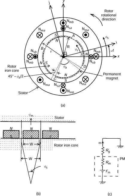
Figure 9.3 Cross section and magnetic equivalent circuit: (a) cross section; (b) enlarged rotor surface; (c) magnetic equivalent circuit
Hence the airgap flux density Bgp can be written as
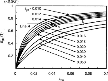
The normalized permanent magnet thickness lm/r and airgap length lg/r with respect to the radius r of the stator inner surface are defined as lmn and lgn, respectively, so that the airgap flux density Bgp can be rewritten:
Figure 9.4 shows the relationship between the airgap flux density Bgp and the normalized permanent magnet thickness lmn for lines of constant airgap length lgn. In general the airgap flux density in an electric motor dictates the motor parameters and performance, most notably the voltage for a given rotational speed (the voltage constant in a dc machine), the efficiency and the utilization of the magnetic steel. The parameters are also governed by the motor geometry, especially the magnet reluctance to effective airgap reluctance ratio. For example, the design point has to be on the line A for an airgap flux density Bgp of 0.6 T (which is 0.6/0.9 = 0.71 T in Figure 9.4) if the permanent magnets have a remanent flux density Br of 1 T with an area ratio S/S′ of 0.9. When the normalized airgap length lgn is 0.016, point a is the design point and therefore the normalized permanent magnet thickness is 0.04. When lgn = 0. 03, point b is the design point. Thus, the desired flux density can be obtained for a given airgap length. This design method is correct for a conventional synchronous permanent magnet machine. However, in the bearingless motor it is necessary to generate a radial suspension force effectively. In the next section, the optimum permanent magnet thickness and optimum airgap length will be analytically derived.
9.4.2 Radial suspension force for unity current
From (9.10) the radial suspension force for unity suspension current under the no-load condition is
where the suspension force ![]() . Note that Ime is equal to Imp at no-load because Imq = 0 in (9.4). An increase in the q-axis motor flux results in an increase in the radial suspension force for unity current, which is desirable. In (9.18) the derivative M′ can be obtained from the mutual inductance matrix shown in (6.32). Differentiating the mutual inductance with respect to the rotor displacement yields
. Note that Ime is equal to Imp at no-load because Imq = 0 in (9.4). An increase in the q-axis motor flux results in an increase in the radial suspension force for unity current, which is desirable. In (9.18) the derivative M′ can be obtained from the mutual inductance matrix shown in (6.32). Differentiating the mutual inductance with respect to the rotor displacement yields
where n4 and n2 are the effective number of turns of the motor and suspension windings respectively, and (lm + lg) is the effective airgap length in the permanent magnet type machine. From Figure 9.3(a) and equation (9.16) the fundamental component Bgp(Ψr) of the airgap flux density due to the permanent magnet field excitation is
For unity current in the motor winding, the MMFs Ama and Amb can be represented as
If the q-axis current Imq is equal to zero then the equivalent current Ime = Imp. So the equivalent currents imae and imbe in (9.2) and (9.3) are
From (9.21) to (9.24) the resultant MMF Amp is
Since the reluctance in the effective airgap between the stator and rotor iron cores can be obtained from

the airgap permeance P per segment arc angle ΔΨs can be derived using
From (9.25) and (9.26) the airgap flux ψgM per ΔΨs becomes
Hence the airgap flux density BgM(Ψr) can be derived by dividing the ψgM by the permanent magnet area S. Since S = (R + lm)ΔΨsl then BgM(Ψr) can be written as
Equating (9.20) and (9.28) and then solving for Imp yields
where the kip is given by
If lm and lg are much less than r, and kip is nearly equal to 1, then Imp can be approximated to
Substituting (9.19) and (9.31) into (9.18) yields the radial suspension force for unity current as
The first term of (9.32) cannot be increased without an increase in motor dimensions or an improvement of the permanent magnet material. The second term depends significantly on the ratios of the permanent magnet thickness and the airgap length to the radius of stator inner surface. If the second term reaches a maximum then the radial suspension force is also at a peak.
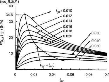
Figure 9.5 shows the characteristics for the relationship between the radial suspension force for unity rms suspension current and the normalized permanent magnet thickness for varying airgap length. It is seen that the radial suspension force for unity current is maximum for the condition of lmn = lgn. This maximum value increases with decreasing lgn. Therefore it is recommended that the permanent magnet thickness is set to be equal to the airgap length and that the airgap length is as small as possible. However, if the permanent magnet thickness is set to be equal to the airgap length, the airgap flux density of the permanent magnet field excitation is expressed as Bgp = 0.5 BrS/S′ by (9.17) so that the flux density Bgp is no more than 0.6 T, even if rare-earth permanent magnets with a cylindrical structure are employed where Br = 1.2T and S/S′ = 1. It will be less than 0.6 T if a segmented permanent magnet rotor structure where S/S′ < 1 is employed. In general, a high airgap flux density is preferred to maximize the rotational torque capability (except with high speed motors). In addition, thin permanent magnets may be irreversibly (or permanently) demagnetized. Therefore, it is necessary that the permanent magnet thickness and the airgap length should be designed so that the airgap flux density and the permanent magnet permanent demagnetization issues are addressed. This leads to a compromise between these issues and the need for a high radial suspension force per unity suspension current. The issue of irreversible demagnetization is discussed in section 9.5.
9.5 Irreversible permanent magnet demagnetization and MMF limitations of stator windings
In surface permanent magnet bearingless motors, thin permanent magnets are preferable to generate the radial suspension force with less current. Both motor and suspension fluxes are superimposed on the rotor permanent magnets. Therefore, irreversible (or permanent) demagnetization of the permanent magnets is a more serious problem in these motors than in conventional electric motors.
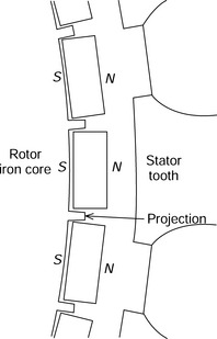
In order to protect the permanent magnets against irreversible demagnetization, a rotor structure with small laminated projections from the rotor iron core between the magnets (as shown in Figure 9.6) was proposed [7] so that the leakage flux goes through the permanent magnet, air, the projection and the rotor iron core before returning to the permanent magnet. Because of these small projections (that are fabricated into the rotor lamination stamping), the permanent magnets can also be easily fixed to the rotor. The protection of the magnet against irreversible demagnetization is slightly increased when compared to a rotor structure without the small inter-magnet projections. However, the magnet leakage flux is also increased.
It is therefore necessary that the maximum current ratings of the motor and suspension windings are properly determined so that the permanent magnets are not irreversibly demagnetized. In the next section the positioning of the permanent magnets which produces high demagnetization is assessed [10] and the maximum MMFs of the stator windings at the demagnetization limit are derived [11].
9.5.1 Permanent magnet positioning for high demagnetization
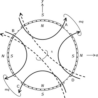
Figure 9.7 shows an example with q-axis motor current and suspension current flux paths. The rotor angular position ωt is 0 deg. When the q-axis motor flux ψmq is generated as shown, torque is generated in the counter-clockwise direction. In this case, ψmq goes through the permanent magnets denoted as A, B, C and D in the opposite direction to their magnetization. In addition, the suspension flux ψs is shown. Note that both ψmq and ψs go through permanent magnet D against the magnetization so that D is the most critical permanent magnet. The q-axis motor flux ψmq is synchronously rotating with the rotor but the suspension flux ψs is rotating with a frequency twice that of the rotor, i.e., ψs is not synchronized to the revolving rotor magnetic field. Therefore, not only D but also A, B and C will experience the same degree of demagnetization at some point with the possibility of irreversible demagnetization.
9.5.2 Limits of stator winding MMFs
In this section the MMF limits of the motor and suspension winding currents due to permanent magnet demagnetization are derived.
The flux density in the most critically demagnetized permanent magnet, including the effects of the motor and suspension MMFs as well as the permanent magnet magnetization itself, can be calculated. The permanent magnet field excitation has already been obtained in a previous section, so let us derive the flux due to the motor and suspension winding MMFs. When there is only a q-axis component in the motor winding current, from (9.2) to (9.5):
From (9.21), (9.22), (9.33) and (9.34), the resultant MMF Am is
Hence, from (9.26) and (9.35), the airgap flux due to the motor winding current ψMm per segment and angle becomes
The total resultant airgap flux ψgm per segment due to the permanent magnet flux ψm and the motor winding MMF flux ψMm can be obtained by (9.15) and (9.36). Let us consider the airgap region under the pole face. We can define the mechanical arc of the permanent magnets for one pole as Ψa, this is about 80 deg for the example in Figure 9.7.
The critical value of ψgm will occur at the angular positions of (90 − Ψa/2), (180 − Ψa/2), (270 − Ψa/2) and (−Ψa/2), as denoted by A, B, C and D in Figures 9.3(a) and 9.7. The surface of the permanent magnets will be most susceptible to demagnetization, so substituting Ψr = (90 − Ψa/2), (180 − Ψa/2), (270 − Ψa/2) and (−Ψa/2) into (9.36) gives the minimum flux per segment through the magnet surface, which can be expressed as
Now let us consider the influence of the suspension winding MMF. The maximum airgap flux ψMr per segment due to the suspension winding MMFs is similar to (9.36) so that
Hence, the minimum value ψmin on the surface of permanent magnets A, B, C and D is
From (9.37) to (9.39), the minimum flux density Bmin is therefore
As the MMF n4Imq of the motor winding and the MMF n2Is2 of the suspension winding increase, the flux density Bmin decreases. The minimum flux density occurs at the current limits.
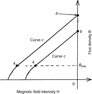
Figure 9.8 shows B–H curves for a rare-earth permanent magnet. When the operating point is between points b and k on curve c, the permanent magnet is not irreversibly demagnetized. However, if the reverse magnetic field is increased further then the operating point will be moved to the left of point k so that the permanent magnet is irreversibly demagnetized. The flux density at point k is the minimum value Bmin. Substituting this minimum value Bmin and the motor dimensions into (9.40) and solving for the MMF n4Imq and n2Is2, one can obtain the maximum MMF values. When the permanent magnet temperature rises, the B–H curve moves in the direction of point 0 from curve c to curve c′. Therefore, the permanent magnets can be permanently demagnetized at a lower magnetic field if the temperature is raised.
For a machine with the specification shown in Table 9.1:
(a) Derive the flux density BPM on the permanent magnet surface using the expression for the permanent magnet MMF.
(b) Derive the flux densities Bm and Bs due to the motor and suspension winding MMFs at a current rating of 7.8 A for both.
(c) Derive the minimum flux density Bmin on the permanent magnet surface at the current ratings.
(d) Derive Bmin when the motor and suspension winding currents are twice the rated values.
(a) The first term ![]() on the right-hand side of (9.40) is the flux density BPM on the permanent magnet surface. Substituting lm = lg = 1 mm and Br = 1T yields BPM = 0.5T.
on the right-hand side of (9.40) is the flux density BPM on the permanent magnet surface. Substituting lm = lg = 1 mm and Br = 1T yields BPM = 0.5T.
(b) The second and third terms on the right-hand side of (9.40) are the flux components due to the motor and suspension winding MMFs. Therefore, Bm = 0.17 T and Bs = 0.07 T at a current rating of 7.8 A.
(c) From the above results, Bmin = 0.26 T.
(d) Substituting Imq = Is2 = 7.8 × 2 = 15.6 A into (9.40) yields Bmin = 0T. If the acceptable flux density of the employed permanent magnet is 0 T then the maximum currents in the motor and suspension windings are 15.6 A, i.e., twice the rated current values.
9.6 Control system configuration
Accurate information on both the magnitude and direction of the airgap flux is required to regulate the rotor radial position precisely. In this section, a control system configuration which considers the armature reaction is introduced. Figure 9.9 shows the control system block diagram of a cylindrical permanent magnet synchronous bearingless motor [5,6]. In the rotor radial position controller, the rotor radial displacements x and y in x- and y-directions are detected by gap sensors. The differences between the detected displacements and the commands x* and y* are amplified by proportional-integral-derivative (PID) controllers so that the radial suspension force commands F*x and F*y in x- and y-directions are correctly determined. The rotor radial position commands are set to be the center position in x- and y-axes, i.e., x* = 0, y* = 0. As derived in (9.7), the radial suspension force commands are transformed into the radial suspension winding current commands i*sa and i*sb for the sa- and sb-phases so that
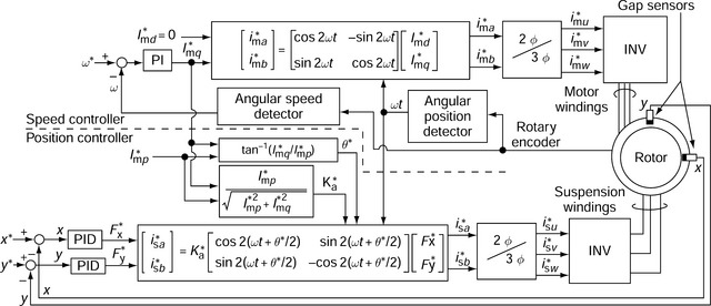
where I*mq is the q-axis motor current command and I*mp is the equivalent current command for the permanent magnets. The current command I*mq is determined by amplifying a speed error in a proportional-integral (PI) controller. The error is calculated using the detected angular speed ω (from a rotary encoder) and the speed command ω*. The current command I*mp = Eo/Xm, where Eo is the measured open-circuit voltage and Xm is the measured armature reactance. Substituting (9.42) into the right-hand side coefficient of (9.41) and rearranging yields
The first term l/m′I*mp on the right-hand side is a constant and the gains of the PID controllers are adjusted to be equal to l/m′I*mp. Let us now replace the second term as K*a so that
K*a is the ratio of the permanent magnet excitation to the resultant flux from both the permanent magnet excitation and the q-axis current. In the control system, the radial suspension force commands F*x and F*y are multiplied by K*a. This varies in accordance with the q-axis motor current command I*mq so that the loop gain of the rotor radial position controller can be successfully maintained at a constant value. The phase command θ* of the radial suspension winding current is determined by the calculation of tan−1(I*mq/I*mp), where I*mq/I*mp is the ratio of the q-axis current to the equivalent current of the permanent magnet field excitation.
The amplitude and phase of the radial suspension winding current commands I*sa and I*sb are controlled by the q-axis motor current command I*mq. As a result, by consideration of armature reaction, the shaft can be successfully suspended without mutual interference between the radial suspension force components in two perpendicular axes.
References
[1] Bichsel, J., “The Bearingless Electrical Machine”. NASA-CP-3152-PT-2, 1992:561–573.
[2] Okada, Y., Shimura, S., Ohishi, T., “Horizontal Experiments on a Permanent Magnet Synchronous Type and Induction Type Levitated Rotating Motor”. Proc. of IPEC-Yokohama, 1995:340–345.
[3] Steele, B.A., Stephens, L.S., “A Test Rig for Measuring Force and Torque Production in a Lorentz, Slotless Self Bearing Motor”. Proc. of 7th Int. Symposium on Magnetic Bearings, 2000:407–412.
[4] Nenninger, K., Amrhein, W., Silber, S., Trauner, G., Reisinger, M., “Magnetic Circuit Design of a Bearingless Single-Phase Slice Motor”. Proc. of 8th Int. Symposium on Magnetic Bearings, 2002:265–270.
[5] Ooshima, M., Miyazawa, S., Chiba, A., Nakamura, F., Fukao, T., “Parameter Measurements and Radial Position Control Characteristics of a Permanent Magnet-Type Bearingless Motor Under Loaded Conditions”. Trans. IEE, Japan, Vol. 120-D, No. 8/9, 2000:1015–1023.(in Japanese)
[6] Ooshima, M., Miyazawa, S., Chiba, A., Nakamura, F., Fukao, T., “Performance Evaluation and Test Results of a 11 000 r/min, 4 kW Surface-Mounted Permanent Magnet-Type Bearingless Motor”. Proc. of 7th Int. Symposium on Magnetic Bearings, 2000:377–382.
[7] Ooshima, M., Miyazawa, S., Deido, T., Chiba, A., Nakamura, F., Fukao, T., “Characteristics of a Permanent Magnet-Type Bearingless Motor”. IEEE Transactions on Industry Applications, Vol. 32, No. 2, 1996:363–370.
[8] Ooshima, M., Chiba, A., Fukao, T., Rahman, M.A., “Design and Analysis of Permanent Magnet-Type Bearingless Motors”. IEEE Transactions on Industrial Electronics, Vol. 43, No. 2, 1996:292–299.
[9] Ooshima, M., Miyazawa, S., Deido, T., Chiba, A., Nakamura, F., Fukao, T., “An Analysis and Characteristics of a Permanent Magnet-Type Bearingless Motor”. Trans. IEE Japan, Vol. 115-D, No. 9, 1995:1131–1139.(in Japanese)
[10] Chiba, A., Onoya, S., Kikuchi, T., Ooshima, M., Miyazawa, S., Nakamura, F., Fukao, T., “An Analysis of a Prototype Permanent-Magnet Bearingless Motor Using Finite Element Method”. Proc. of 5th Inc. Symposium on Magnetic Bearings, 1996:351–356.
[11] Ooshima, M., Miyazawa, S., Chiba, A., Nakamura, F., Fukao, T., “A Rotor Design of a Permanent Magnet-Type Bearingless Motor Considering Demagnetization”. IEEE Proceedings of the power conversion conference-NAGAOKA, Vol. 2, 1997:655–660.