
Applications and test machines
In this chapter some examples of bearingless drives that have been developed by various manufacturers are presented. The characteristics, requirements and development purposes are described. The applications for these drives are:
21.1 Canned pumps and drives [1–4]
Canned pumps are used in pumping applications where a fluid leak should be avoided and contact with steel components will cause corrosion. For example, hydrochloric acid is pumped around paper mill plants using canned pumps because the processing of wood chips and recycled paper uses this corrosive liquid. Ball bearings cannot be used here because of steel corrosion. Usually carbon slide bearings are used instead. These are cylindrical in shape. During operation there is no mechanical contact because there is fluid between the carbon cylinder and the stationary bearing sheath when pumping at speed. However, there is contact during starting, causing wear. In addition, the bearings may fail if small particles contaminate the fluid. Hence the life time of a carbon slide bearing is short and it is very difficult to see if the pump has a small but developing bearing problem. Therefore it is known for them to fail and seize suddenly in which case they should be replaced in very short time to prevent the loss of production. (Conventional bearings usually wear in a more gradual manner which can be diagnosed – allowing replacement in scheduled downtime.) The suspension problem in conventional canned pumps may be overcome by the use of a bearingless drive and/or magnetic bearings.
Figure 21.1 shows a picture of a test canned pump and drive developed by Ebara Research Co. Ltd, Japan. Figure 21.2 shows a cross section of the canned pump. The pump impeller is at the right-hand end of the unit. Fluid enters the impeller from the right and then is pumped in an upward direction. The other half of the unit consists of the bearingless motor units and a magnetic thrust bearing. There are two bearingless motor units and these are responsible for the torque and radial suspension of the rotor. The four radial axes are actively suspended by the two bearingless motor units, and the magnetic thrust bearing, which is located at the left-hand end, generates an axial magnetic force to balance the significant thrust force caused by the pump impeller. The rotating component is surrounded by a metal can made of Hastelloy, which is a corrosion-resistant metal. The inner surface of the stationary component is also protected by a thin cylindrical Hastelloy can and the space between the Hastelloy cans is filled by the fluid. While the pump is small, the motor and suspension components are quite large. The manufacturer of this pumping unit specializes in the integration of mechanical and electrical components in this way.
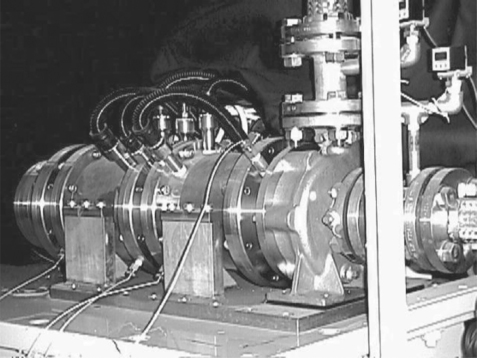
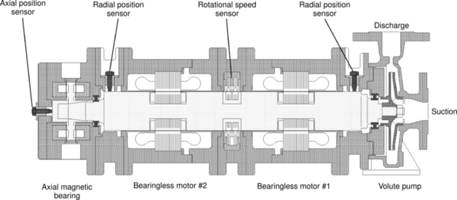
Table 21.1 shows the specification of the canned pump. The rotor diameter is 68 mm and the axial length is 50 mm for one bearingless unit. The input power is about 2.2 kW. The head is 24 m and the flow of the pump is 180l/min. Another 15-kW machine is also described in [2].
Table 21.1
| Rotor diameter | 68 mm |
| Rotor stack length | 50 mm |
| Airgap length | 0.6 mm |
| Rotating part length | 600 mm |
| Rotating part weight | 14 kg |
| Can thickness | 0.2 mm |
| Head | 24 m |
| Flow rate | 180l/min |
(Courtesy: Ebara Research Co. Ltd)
Figure 21.3 shows a picture of a 30-kW canned pump developed by Sulzer Pumps Ltd and Sulzer Electronics Ltd, Switzerland [3–4]. Figure 21.4 shows a cross section of this canned pump. The fluid enters from the left-hand side and pumped in the upward direction by the pump impeller. On the right-hand side of the impeller is a radial magnetic bearing. This takes the form of a homopolar permanent magnet machine. The windings are arranged to operate in differential mode so that no current is required when there is no radial force. A 3-phase winding set is used in the magnetic bearing which is driven by a 3-phase inverter. A controller from a general-purpose inverter is modified to act as the current regulators for the magnetic bearing, and only three power wires are required for two-axis active magnetic suspension. This is a nice development of the radial magnetic bearing and it should be noted that this is an application using a bearingless motor with a static magnetic field.
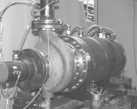
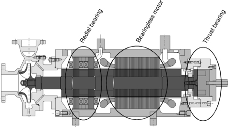
The middle part of the pump-drive is a bearingless unit with an input volt-ampere rating of 45 kVA. An induction type of bearingless motor is used. The bearingless unit generates torque and 2-axis radial forces. On the right-hand side is a magnetic thrust bearing. In total, five axes are actively controlled by magnetic forces. The head and flow for the pump are 62 m and 30 l/s respectively, and the radial force is rated at 3500 N.
21.2 Compact pumps, bubble bed reactor
21.2.1 Compact pump [5]
Figure 21.5 shows two pictures of compact pumps from Levitronix GmbH. These have ratings of 50 and 300 W. The plastic upper components are the pump casings while the lower metal components are the frames for the bearingless drives. Figure 21.6 shows a cross section of one of these pumps. The fluid enters the inlet at the top of the pump and is pumped out of the radially orientated outlet. A plastic pump impeller is located on the rotor which also has integrated permanent magnets. The permanent magnets are magnetized in the radial direction allowing the generation of torque and two-axis radial forces. The stator iron teeth are located around the rotor on the outside of the plastic casing. The stator teeth are bent down into a C-shape so that the diameter of the pump is minimized. The motor and suspension coils are wound around the stator teeth and the suspension coils are operated in differential mode to minimize the current requirements. Only two radial magnetic forces are actively regulated; however, the rotor is suspended passively to restrict the thrust and tilt movements, and also the rotor diameter and thickness are carefully designed to realize stable magnetic suspension with just two axes of active suspension. There is no mechanical seal in this pump so that no fluid leakage is expected. The applications for this sort of pump are external blood pumps, semiconductor process pumps, chemical process pumps, food process pumps and other pump applications where a mechanical seal should be avoided.
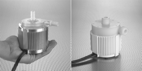
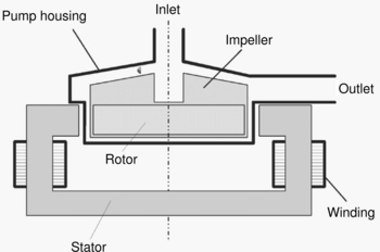
Table 21.2 gives the specifications of the two pumps. The head is 8 m and the flow is 18 l/min for the small pump and 25 m and 50 l/min for the large pump.
21.2.2 Bubble bed reactor [6]
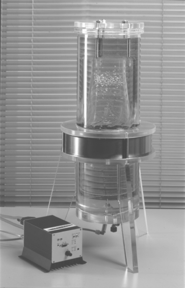
Figure 21.7 is a picture of a bubble bed reactor [6]. In this, animal cells are grown in the reactor fluid. Oxygen is supplied from a nozzle at the bottom and there is a downstream fluid flow so that the oxygen bubbles stay in the fluid. The downstream is generated by a pump impeller. Usually, the pump impeller is driven by an external drive. The torque transfer mechanism requires a mechanical suspension structure to support the impeller, and also a shaft and a mechanical seal are required. If the cell is broken at the seal then the fluid can be contaminated. Alternatively the bearingless motor provides a magnetic suspension force and rotational torque to the pump impeller without a mechanical seal so that the possibility of contamination is reduced. The impeller is actively suspended in two perpendicular axes in the fluid. Other degrees of freedom for the motion is restricted by the careful design of the rotor diameter and thickness.
In the electro-mechanical structure, the permanent magnets are magnetized in the axial direction and placed on a ferromagnetic ring. The permanent magnets provide homopolar radial flux flow across the airgap between magnetic bearing iron poles and the rotor ring. Attractive forces are generated between the bearing iron poles and the rotor ring and these are regulated by the current in the magnetic bearing winding.
21.2.3 Blood pump [7,8]
Figure 21.8 shows a picture of an implantable blood pump under development in Ibaraki University, Japan. Figure 21.9 shows a diagram of the electromagnetic structure. The stator core, not shown in the figure, is located inside the ring-shaped rotor. The rotor ring is supported by two-axis active magnetic suspension. Several eddy current sensors are illustrated and used for test purposes. On the rotor ring, a plastic impeller is attached; the blood comes in through the inlet on the top of the blood pump and exits through the outlet. The plastic impeller design is quite important to avoid haemolysis.
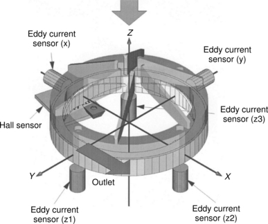
In blood pump applications, magnetic suspension is highly desirable. In conventional blood pumps used in surgery, the operation time is limited to several hours to avoid clogging problems. These are due to blood particles being destroyed in the blood pump. These broken particles adhere to the seal which may eventually clog because of this build-up. Also the broken particles can result in a thrombus. Therefore, supporting a pump impeller with magnetic suspension is an effective way to counteract these problems. A blood pump with integrated magnetic bearings has been shown to have a long operating life when tested in trials.
Another application is the artificial heart. Compact blood pumps implanted into the human body may help many people. There are many requirements for a blood pump; from an electromechanical point of view, these are
Electric power is supplied through human skin via a transformer. The primary side of the transformer is fixed on the outside of the body while the secondary side is buried under patient’s skin. If the required power is low then the power supply and pump can be compact. In normal human activity several watts are required to pump the blood, and a high efficiency motor and pump are required. Power losses in the magnetic suspension should be minimized to avoid a temperature rise – the pump should operate as close to body temperature as possible.
Another experimental blood pump has been manufactured in Switzerland and the USA [8]. The structure is basically similar to the compact pump described in this section. The diameter is 69 mm and thickness is 30 mm for the motor component. These compact structures provide a promising future for the development of the blood pump.
21.3 Spindle motor and semiconductor processing
Some computer-related machines are required to run at high speeds. In hard disk storage, disks are driven by an electrical motor at a constant speed, for example 15000r/min. To enhance the data transfer speed some hard disks have an even higher speed. High-speed hard disks can suffer from excessive heat generation. As the rotational speed increases, mechanical bearing loss also increases so that the motor power increases likewise. Hence the heat generation due to electrical and mechanical losses increases, resulting in raised temperature which shortens life time and increases the possibility of premature failure. If magnetic suspension is used then the drive loss can be reduced and hence lower motor power is required. There is now a need for even higher speed drives in DVD and CD applications.
Polygon mirror scanners are used in information-processing machines such as laser printers. These also require a high-speed drive. In order to enhance the processing speed, the rotational speed of the drive motor needs to be increased.
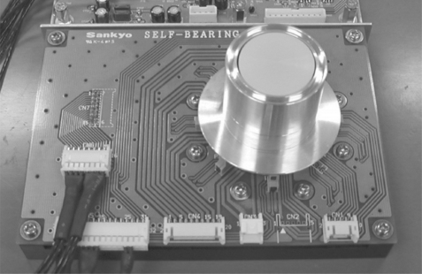
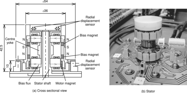
Figure 21.10 shows a drive developed by Sankyo Seiki Mfg Co., Japan. An aluminium sleeve is seen on the printed board. Figure 21.11(a,b) shows a cross section and side view of the spindle without the aluminium sleeve. The upper electromagnet is a hybrid type magnetic bearing while the lower one is a bearingless motor with radial magnetic suspension. The rotor is external to the stator. In addition, permanent magnet bias rings are seen; these produce the axial flux required for homopolar excitation of the stator cores. Radial displacement sensors are placed above the unit. Other radial displacement sensors are located on the printed board for the detection of radial movement of the lower end.
Another notable bearingless motor hard disk drive developed in Switzerland is described in [10].
21.3.2 Semiconductor processing [11]
In semiconductor wafer processing, the surface of the silicon wafer is chemically processed. Usually the silicon wafer is placed on a turntable during this chemical process, which includes the use of a corrosive chemical. The life expectancy of the turntable is limited because the supporting bearing is damaged by the corrosive chemical leaking in through the seal. If the turntable is suspended by magnetic suspension, the chemical process can be separated from the drive and bearing since the seal is eliminated. Moreover, both sides of the wafer can be processed simultaneously.
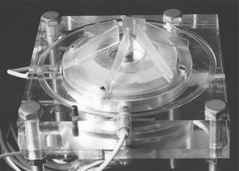
Figure 21.12(a,b) show a bearingless system for semiconductor processing. In Figure 21.12(a), the rotor, stator and controller are shown. In Figure 21.12(b), a cross section of the silicon wafer placed on the rotor ring is illustrated. This structure is similar to the bubble bed reactor bearingless motor.
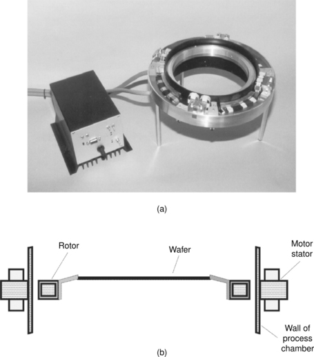
Figure 21.12 Semiconductor wafer suspension: (a)wafer suspension with a bearingless motor; (b) side view. (Courtesy: Levitronix GmbH)
In this chapter, we have seen several examples of bearingless motors that are either commercial prototypes or early production versions. As described in Chapter 1, the possible applications for the bearingless drive are varied and wide and some notable developments have been included in this chapter. Space constraint prevents the inclusion of further examples. Most of the applications take advantage of non-contact suspension and low suspension losses. More applications will be seen in the future as the drive technology is further developed.
References
[1] Satoh, T., Mori, S., Ohsawa, M., “Study of Induction-Type Bearingless Canned Motor Pump”. Institute of Electrical Engineering of Japan (IEEJ), International Power Electronics Conference (IPEC), Tokyo, Japan, April 3–7, 2000:389–394.
[2] Ohsawa, M., Mori, S., Satoh, T., “Study of the Induction type Bearingless Motor”. Seventh International Symposium on Magnetic Bearings (ISMB), 2000:389–394. [August Zurich].
[3] Redemann, C., Meuter, P., Ramella, A., Gempp, T., “Development and Prototype of a 30kW Bearingless Canned Motor Pump”. IPEC, 2000:377–385. [April, Japan].
[4] Redemann, C., Meuter, P., Ramella, A., Gempp, T., “30 kW Bearingless Canned Motor Pump on the Test Bed”. Seventh International Symposium on Magnetic Bearings (ISMB), 2000:189–194. [August 2000 Zurich].
[5] M. Neff, N. Barletta and R. Schoeb, “Bearingless Centrifugal Pump for Highly Pure Chemicals”, ISMB – 8, August 2002, Mito, pp. 283–287.
[6] Schoeb, R., Barletta, N., Weber, M., von Rohr, R., “Design of a Bearingless Bubble Bed Reactor”. ISMB, 1998:507–516.
[7] Masuzawa, T., Kita, T., Okada, Y., “An Ultradurable and Compact Rotary Blood Pump with a Magnetically Suspended Impeller in the Radial Direction”. International Society for Artificial Organ, Vol. 25, No. 5, 2001:395–399.
[8] Schoeb, R., Barletta, N., Fleischli, A., Foiera, G., Gempp, T., Reiter, H.G., Poirier, V.L., Gernes, D.B., Bourque, K., Loree, H.M., Richardson, J.S., “A Bearingless Motor for a Left Ventricular Assist Device (LVAD)”. Seventh International Symposium on Magnetic Bearings (ISMB), 2000:383–388. [August Zurich].
[9] Kanebako, H., Okada, Y., “New Design of Hybrid Type Self-Bearing Motor for High-Speed Miniature Spindle”. ISMB – 8 August, 2002:65–70. [Mito].
[10] Vuillemin, R., Aeschlimann, B., Kuemmerle, M., Zoethout, J., Belfroid, T., Bleuler, H., Cassat, A., Passeraub, P., Hediger, S., Besse, P.A., Argondizza, A., Tonoli, A., Carabelli, S., Genta, G., Heine, G., “Low Cost Active Magnetic Bearings for Hard Disk Drive Spindle Motor”. ISMB, Boston, US, 1998:3–9.
[11] www.levitronix.com.