
Homopolar, hybrid and consequent-pole bearingless motors
Bearingless motors can be classified into several groups. The major group produces suspension force by the interaction of n-pole and (n ± 2)-pole fluxes (or p-pole-pair and p ± 1-pole-pair). However, homopolar and hybrid bearingless motors belong to another group where the suspension force is generated by the interaction of a homopolar flux and a 2-pole flux, which is similar to the homopolar type of radial magnetic bearing, although the theory of operation can be unified by considering the homopolar airgap flux as a flux wave with zero pole number.
In this chapter, the structures and characteristics of homopolar, hybrid and consequent-pole bearingless motors are described.
14.1 Structures and principles
14.1.1 Homopolar magnetic bearing
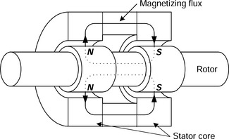
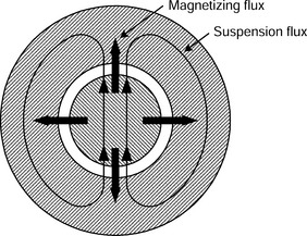
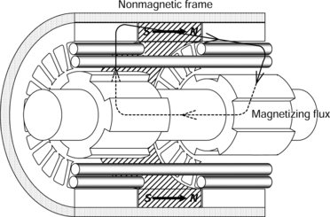
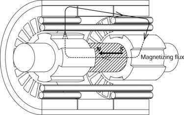
Figure 14.1 shows the structure of a homopolar-type radial magnetic bearing. Permanent magnets or field windings are normally placed between the stator cores to produce a magnetizing flux. This flux flows along the rotor axis and through both pairs of the cores. Therefore the surface of each rotor core is magnetized with a unidirectional flux or a single pole (which can also be considered as a zero pole since it is constant). Radial forces for rotor suspension can be generated with an additional suspension flux superimposed onto the magnetizing flux. Figure 14.2 shows the cross section of an N-pole (north-pole) rotor and stator with the main paths of the magnetizing and suspension fluxes illustrated. Radial arrows show the magnetizing flux; the other core combination would have these flowing in the opposite direction. The 2-pole suspension windings are wound separately on each stator core and the flux is always perpendicular to the rotor axis. In Figure 14.2, the flux is increased in the upper section of the airgap and decreased in the lower section of the airgap. The unbalance of this flux distribution produces a radial force in the upward direction on the rotor. The magnitude of the radial force is adjusted by varying either the magnetizing flux or the suspension flux. A horizontal radial force can be produced with a 2-pole suspension flux that is perpendicular to the 2-pole flux in Figure 14.2. Therefore, an adjustable radial force on the rotor can be generated in all directions on each rotor core so that the rotor radial position has four degrees of freedom; these can be controlled in the same way as the homopolar magnetic bearing shown in Figure 14.1. Since the rotor is symmetrical and the zero-pole flux is uniform, the radial force is produced independently of the rotor rotational position. The advantages of homopolar magnetic bearings are:
1. No bias current is required if permanent magnet magnetization is employed.
2. Low current requirement for magnetic suspension because the suspension flux does not flow through the permanent magnets so that the effective airgap length is relatively small.
Both the homopolar bearingless motor and the hybrid bearingless motor, as described below, have homopolar structures. The magnetizing flux of a hybrid motor flows along the rotor axis, while the mechanism for rotor suspension is the same as that of the homopolar magnetic bearing. The structures and mechanisms for torque and suspension force production are discussed in the following sections.
14.1.2 Homopolar bearingless motors
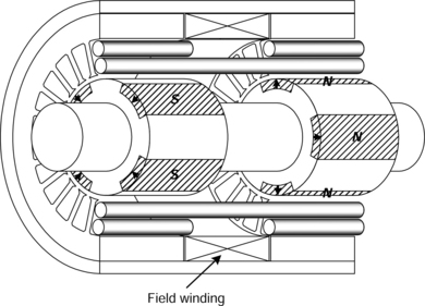
Figure 14.3 shows the structure and magnetizing flux path of a homopolar bearingless motor [1–3]. There are two rotor cores and two stator cores in the motor. Each stator core has both motor and suspension windings. The 8-pole motor winding is wound in both cores together while the 2-pole suspension windings are wound separately in each core. Each rotor core has four salient poles but no windings or permanent magnets (similar to the switched reluctance type machine). A field winding is wound between the stator cores. This winding can be replaced with permanent magnets between the stator or rotor cores. If this is the case then it becomes a hybrid bearingless motor.
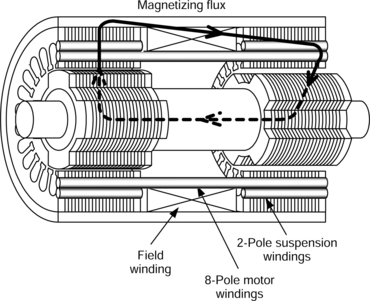
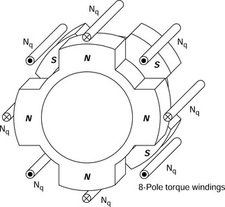
The main flux (as generated by the field current and a d-axis motor current) passes through the stator cores and circulates between the cores via the casing and shaft as shown in Figure 14.3. The salient poles on the left-hand rotor core are north poles whereas they are south poles on the right-hand rotor core. Looking into the rotor in the axial direction from the left, we can see that the south poles and north poles are offset by one rotor pole pitch as shown in Figure 14.4. The arrangement of the magnetized poles is similar to that of an 8-pole motor so that torque is generated in a similar manner to that of an 8-pole synchronous machine. The magnetizing flux can be generated by both the field current and d-axis motor current. With variation of the ratio of the field current and d-axis motor current, the power factor and the terminal voltage of the machine are adjustable.
The mechanism of producing radial force is virtually the same as for the homopolar magnetic bearing, as described in the previous section. By superimposing a 2-pole suspension flux on the magnetizing flux a suspension force in any direction can be generated. Although the airgap flux is concentrated in the salient poles of the rotor cores, a constant suspension current generates a constant radial force, which is independent of the rotor rotational position if the motor has an appropriate number of poles. One of the remarkable characteristics is that the rotational position of the revolving magnetic field is not required for the control of the radial force so that it is possible to suspend the rotor with a simple and robust controller.
14.1.3 Hybrid bearingless motors
There are several different arrangements of the hybrid bearingless motor based on the permanent magnet locations. Some typical structures are shown in Figures 14.5, 14.6 and 14.7. The structure shown in Figure 14.5 has permanent magnets between the stator cores to develop the magnetizing flux. The flux path of the magnetizing flux is the same as that of the homopolar magnetic bearing. Each stator core has a 2-pole suspension winding to produce radial force so that four radial degrees of freedom of rotor position can be magnetically regulated.
Several further variations and modifications are possible. For instance, one of the rotor cores can be cylindrical and act as a magnetic bearing only. Also the permanent magnets can be on the rotor surface. As an example, [4] describes a 6-pole permanent magnet motor. Figure 14.6 shows a magnetizing permanent magnet on the rotor where the permanent magnet is oriented in the axial direction and located around the shaft. Another modification uses four permanent magnets attached to the rotor surface [5]. The permanent magnets can be embedded between rotor poles as shown in Figure 14.7. This structure is similar to the consequent-pole bearingless motor.
14.1.4 Consequent-pole bearingless motors
The rotor and stator of the consequent-pole bearingless motor do not work in tandem and there is no homopolar flux, although the rotor has similar topology to the homopolar and hybrid machines (which have one magnet per rotor pole-pair); the production of the radial force is slightly different. However, the radial force production of consequent-pole machines is also different from the more usual type of permanent magnet bearingless motor (where there are two magnets per rotor pole-pair). Therefore this type of machine lies between the homopolar and multi-polar types of machine – it exhibits characteristics from both, in terms of torque and suspension force production.
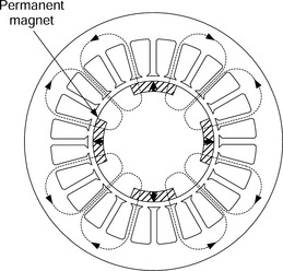
Figure 14.8 shows a cross-sectional view of a consequent-pole bearingless motor [6]. All the flux flows perpendicular to the rotor axis. The thick arrows indicate the polarities of the permanent magnets and the dotted lines show the 8-pole flux paths of the permanent magnets. The polarities are different from those of the conventional 4-pole inset permanent magnet motors (which have the same number of magnets). The surfaces of the permanent magnets are magnetized as north poles, and the surfaces of the iron poles are consequently magnetized as south poles. The stator has both an 8-pole motor winding and a 2-pole suspension winding (whereas a more standard p-pole-pair bearingless permanent magnet machine would have a p-pole-pair motor winding and a p + 1 or p − 1 pole-pair suspension winding). Torque is produced by the interaction of the 8-pole permanent magnet flux with the 8-pole motor winding currents. 2-pole suspension flux flows mainly through the salient iron poles on the rotor because the permanent magnets have high magnetic reluctance. Superposition of the permanent magnet and suspension current fluxes under the salient rotor poles produces an unbalanced airgap flux distribution which results in a radial force. Since the permanent magnet flux can be thought of as a homopolar flux under the iron rotor poles (where the suspension winding current generates a 2-pole flux) we can see that we have met the criterion for suspension, where we have airgap fields with pole-pairs differing by 1 (2 and homopolar – since 1 pole is not possible because there is no start or finish of the pole, we may also consider homopolar flux as zero-pole or dc). Therefore we can say that the radial force production is similar to that of the homopolar bearingless motor, where a constant radial force is generated with constant suspension winding current at any rotor angular position.
However, in terms of actual airgap fields (and not just flux under the iron poles) a more rigorous mathematical analysis for the consequent-pole machine considers the permeance modulation of the consequent-pole rotor on the 2-pole suspension winding MMF. For a p-pole-pair consequent-pole machine (in this case 8-pole), the rotor will modulate the 2-pole suspension winding MMF to produce p ± 1 pole-pair flux waves (i.e., 6-pole and 10-pole) which produces suspension. Hence, in terms of airgap flux waves, suspension production is different from the homopolar and hybrid machines, which have 2-pole and zero-pole airgap flux waves. Although, as already stated, in a consequent-pole machine, the homopolar action is really quasi-homopolar since it is thought to exist under the iron salient poles only. In the next section, a mathematical derivation is put forward which suggests a 6-pole consequent-pole rotor is not suitable due to a component of the radial force that is a function of rotor rotational position. Using the airgap permeance argument, we can see that a 6-pole consequent-pole rotor will modulate the 2-pole suspension winding MMF, producing 4-pole and 8-pole airgap components. Interaction of the 4-pole flux wave with the two-pole flux wave will produce this rotational-position-dependent radial force. This does not occur in the 8/2-pole winding combination. Hence an 8-pole consequent-pole rotor does not produce this rotational-position component of suspension force.
14.2 Number of poles
Most bearingless motors generate radial force by adding a revolving suspension flux onto the revolving motor flux. In order to generate radial force in a certain direction, the direction of the suspension flux must be varied in accordance with the direction of the motor flux. On the other hand, homopolar and hybrid bearingless motors generate radial force by superimposing a 2-pole suspension flux onto the homopolar flux. Hence the advantage of these types of bearingless motor (and the consequent-pole machine) is that the radial force in a certain direction can be generated with a fixed suspension current for any rotor rotational position and load condition. In the following sections, the radial force is shown to be independent of the rotor angular position and motor torque current.
14.2.2 Flux distributions
Due to the homopolar structure, the flux distributions in the homopolar and hybrid bearingless motors and also the quasi-homopolar distribution of the consequent-pole bearingless motor are quite different from other types of bearingless motor. In this section, the airgap flux density distribution of a homopolar bearingless motor is analysed in order to derive the characteristics of the suspension force. The conditions and assumptions for the analysis are as follows:
1. The magnetizing curve is linear.
2. Only field current If, q-axis motor current imq and suspension current isa are assumed and the MMFs of the motor and suspension currents are distributed sinusoidally.
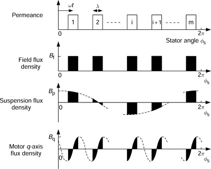
3. The motor winding is m-pole and the suspension winding is 2-pole. Each rotor core has m-poles. The pole arc is λ mechanical radians where 0 < λ ≤ 2π/m. The permeance between the poles is zero.
The airgap flux density can be calculated using the following equation:
where l is the axial stack length of the laminated rotor and stator cores, r is the mean radius of the airgap under the salient poles, P(φs) is the permeance of the airgap as a function of stator angle φs, and A(φs) is the MMF as a function of φs and the rotor angular position with respect to time is ωt. The sign of the flux density indicates the direction of flux across the airgap. Figure 14.9 shows airgap flux density distribution due to the field current, suspension current and q-axis motor current. The sum of these flux densities is
for rotor poles, and
for the inter-pole areas.
14.2.3 Suspension force
The radial forces in the x and y directions are calculated from the square of the sum of the airgap flux density Bg(φs):
If m = 2, i.e., each rotor core has 2 salient poles and the motor winding has 4 poles, the suspension forces can be obtained from:
These suspension forces are functions of rotational angle ωt and q-axis motor flux Bq.
If m = 3, i.e., each rotor core has 3 salient poles and the motor winding has 6 poles, the suspension forces can be obtained from:
These suspension forces are generated independent of the torque current. However, the radial forces vary with the rotor rotational angle ωt.
If m = 4, i.e., each rotor core has 4 poles and the motor windings are 8-pole, the suspension forces can be obtained from:
It is obvious from (14.10) and (14.11) that the radial force is independent of the rotor rotational angle ωt and the q-axis motor flux Bq. Thus, Figures 14.3 to 14.8 are drawn for the case of an 8-pole motor. For higher pole numbers, such as 10, 12, 14, and 16, the radial force is also independent of rotor position and q-axis motor current.
If permanent magnets are mounted on the surface of the rotor shaft or if the rotor core does not have salient iron poles [4–5] then radial forces of m = 3 can be derived by substituting λ = 2π/3 into (14.8) and (14.9), which yields the same equations as for the case of m = 4. It is obvious that the control system for a homopolar, hybrid or consequent-pole bearingless motor is more straightforward compared to that of the other bearingless motors if the number of poles is more than eight for salient pole rotors or more than six for surface-mount (non-salient) permanent magnet rotors. Generally, the radial forces of these bearingless motors can be written as:
where M′f and M′d are constants related to the differential of the mutual inductance with respect to radial displacement.
14.3 Drive systems
Figure 14.10 shows a block diagram of the control system of a homopolar bearingless motor which has an 8-pole motor winding and a 2-pole suspension winding. Although four axis radial positions can be actively controlled by the system, only the left-half position control system is shown.
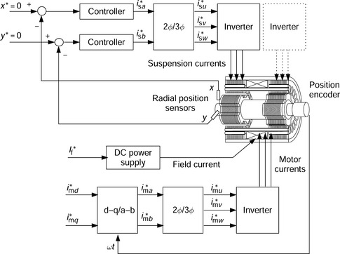
A field current If is supplied by an adjustable dc power supply. The field winding and the power supply can be removed if permanent magnets are used for the excitation. By regulating the field current, the terminal voltage and the power factor of the motor or generator terminals can be controlled in order to realize high-speed and high-efficiency operation.
Motor currents are controlled on the d and q axes and supplied with a 3-phase inverter. The rotational angle is required in the transformation from a rotational d−q coordinate into a fixed stator a−b coordinate system where
The 2-phase motor current commands are transformed into a 3-phase set using
The radial position of the rotor is detected by contactless gap sensors and the signals from these are used to generate the radial force commands. Suspension current commands i*sa and i*sb are directly obtained from the radial force commands in the x- and y-axes and the 2-phase suspension current commands are similarly transformed using (14.14). A 3-phase inverter injects currents into the suspension winding; note that the suspension control system is independent of the motor control system and there is no cross-coupling caused by the main torque-producing current.
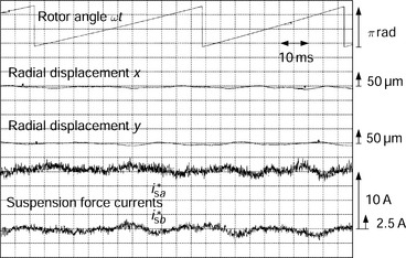
Figure 14.11 shows the experimental results from a homopolar bearingless motor with the control system shown in Figure 14.10. An external static radial force was applied to the rotor and the bearingless motor produced 120 N in the x direction in order to suspend the rotor. The radial position and radial-force suspension currents were measured in this experiment. The field current and the d-axis motor current were kept constant, where If = 1.5 A and Imd = 0A. Figure 14.11 shows that the suspension currents were almost constant, i.e., i*sa = 10 A and i*sb = 0A, even though the rotor speed was approximately 290 r/min.
References
[1] Michioka, C., Toyoshima, Y., Ichikawa, O., Fukao, T., Chiba, A., “Radial Force of Homopolar-Type Bearingless Motors in no Load Condition”. IEEJ Proc. of Meeting of Rotating Machinery, RM-96-24, 1996:91–100.(in Japanese)
[2] Ichikawa, O., Chiba, A., Fukao, T., “Principles and Structures of Homopolar-Type Bearingless Motors”. IEEJ Proc. IPEC-Tokyo 2000 (International Power Electronics Conf.), Vol. 1, 2000:401–406.
[3] Ichikawa, O., Chiba, A., Fukao, T., “Inherently Decoupled Magnetic Suspension in Homopolar-Type Bearingless Motors”. IEEE Trans. on IA, Vol. 37, No. 6, 2001:1668–1674. [November/December].
[4] Okada, Y., Shinohara, K., Ueno, S., Ohishi, T., “Hybrid AMB Type Self Bearing Motor”. Proc. 6th ISMB (International Symp. on Magnetic Bearings), 1998:497–506.
[5] Kanebako, H., Okada, Y., “Development of Hybrid Type Self-Bearing Motor Without Extra Bias Permanent Magnets”. Proc. 7th ISMB (International Symp. on Magnetic Bearings), 2000:347–352a.
[6] Takenaga, T., Kubota, Y., Chiba, A., Fukao, T., “A Principle and a Design of a Consequent-Pole Bearingless Motor”. Proc. 8th ISMB (International Symp. on Magnetic Bearings), 2002:259–264.