Quartz crystals
The properties of a quartz crystal operating near to a frequency of resonance can be represented by an equivalent circuit consisting of an inductance (L1) a capacitance (C1) and a resistance (R1), shunted by second capacitance (Co). The elements L1, C1 and R1 have no physical existence and are introduced to provide an electrical model of a vibrating crystal plate. The commonly used simplified equivalent circuit is shown as Figure 1.
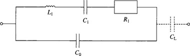
The L1, C1, R1 branch is known as the motional arm where L1 is a function of the vibrating mass, C1 represents the compliance and R1 represents the sum of the crystal losses. Co is the sum of the capacitance between the crystal electrodes plus the capacitance introduced by the crystal terminals and the metal enclosure.
The crystal impedance varies rapidly in the immediate vicinity of the crystal resonance frequencies as shown in Figure 2. There are two zero phase frequencies, one at series resonance (fs) and one at parallel or anti-resonance (fa).
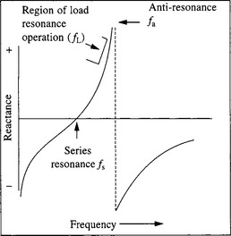
Series Resonance. When a crystal is operating at series resonance its impedance at fs is near to zero but a low active resistance remains which is known as the equivalent series resistance (ESR). The ESR value (expressed in ohms) is a measure of crystal activity and is used as an acceptance criterion.
Parallel or Anti-Resonance. When a crystal is operating at parallel resonance its impedance reaches its peak at fa, as shown in Figure 2. Often the load circuit causes the reactive impedance to resonate in parallel or in series with the oscillator’s load capacitance CL. When a crystal is operating in this condition (fL) the value of CL should be precisely specified and to avoid instability the value of the load capacitance should be several times greater than the value of Co. (Typical range of values for CL = 20 pF to 60 pF)
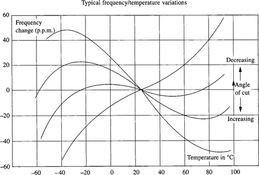
The frequency temperature characteristics of AT-Cut high frequency crystals show a cubic characteristic which, dependent upon the crystal plate design or mode of vibration, has an inflexion point which may be between +27°C and +31°C. By careful control of the crystal cutting angle the two turning points of the curve can be positioned to provide a minimum total deviation of the crystal frequency over a specified temperature range. The frequency/temperature characteristics for the AT-Cut, shown in Figure 3, are substantially valid for most fundamental and overtone types.