
RF transformers
Introduction
RF transformers are used for two main purposes: to convert from one impedance level to another, or to provide electrical isolation between two circuits. Often, of course, isolation and impedance conversion are both required, and a suitable transformer fulfills both these functions with minimal power loss. Examples of transformers used mainly for isolation include those used to couple in and out of data networks and pulse transformers for SCR firing. Examples used mainly for impedance conversion include interstage transformers in MOSFET VHF power amplifiers and the matching transformer between a 50 Ω feeder and a 600 Ω HF antenna. Such a matching transformer may also be required to match an unbalanced feeder to a balanced antenna. With so many basically different applications, it is no wonder that there is a wide range of transformer styles, from small-signal transformers covering a frequency range approaching 100 000:1, to high power HF transformers where it is difficult to cover more than a few octaves.
Transformer basics
Before describing the techniques special to RF transformers, it may be helpful to recap on the operation of transformers in general. Transformer action depends upon as much as possible (ideally all) of the magnetic flux surrounding a primary winding linking with all of the turns of a secondary winding, to which end a core of high permeability magnetic material is often used (Figure 4.1a). Even so, some primary current - the magnetizing current - will be drawn, even when no secondary current flows: this magnetizing current causes the flux Φ, with which it is in phase. The alternating flux induces in the primary a back-EMF EpB nearly equal to the applied voltage Ea (Figure 4.1b). The amount of magnetizing current drawn will depend upon the primary or magnetizing inductance Lm, which in turn depends upon the number of primary turns and the reluctance of the core: the reluctance depends upon the permeability of the core material and the dimensions. There will be some small power loss associated with the alternating flux on the core, due to hysteresis and eddy current losses in the core material. This can be represented by a core loss resistance Rc, connected (like the magnetizing inductance Lm) in parallel with the primary of a fictional ideal transformer (Figure 4.1c). The core loss resistance draws a small primary current Ic in phase with the applied voltage Ea, and this together with the quadrature magnetizing current Im forms the primary off-load current Ipol (Figure 4.1b).

Figure 4.1d shows how (ignoring losses) a load resistance R connected to the secondary winding, appears at the transformer input as a resistance R’ transformed in proportion to the square of the turns ratio. In practice, there are other minor imperfections to take into account as follows. Firstly, there will be a finite winding resistance Rwp associated with the primary winding, and similarly with the secondary winding. Also, not quite all of the flux due to Im in the primary winding will link with the secondary winding; this is called the primary leakage inductance Llp. If we were to apply Ea to the secondary winding, a similar effect would be observed and the secondary leakage inductance is denoted by L1s. These are both shown, along with Lm and Rc, in Figure 4.1c. With negligible error usually, the secondary leakage inductance and winding resistance can be translated across to the primary (by multiplying them by the square of the turns ratio) and added to the corresponding primary quantities, to give an equivalent total leakage inductance and winding resistance L1 and Rw (Figure 4.1e). Figure 4.1f shows the transformer of Figure 4.1e on load, taking the turns ratio to be unity, for simplicity. For any other ratio, Epb/Es and Is/ I’p would simply be equal to the turns ratio Np/Ns. You can see that at full load, the total primary current is almost in antiphase with the secondary current, and that if the load connected to the secondary is a resistance (as in Figure 4.1e and f), then the primary current lags the applied voltage very slightly, due to the finite magnetizing current.
R.F. considerations
The foregoing analysis is perfectly adequate in the case of a mains power transformer, operating at a fixed frequency, but it is decidedly oversimplified in the case of a wideband signal transformer, since it ignores the self- and interwinding-capacitances of the primary and secondary. Unfortunately it is not easy to take these into account analytically, or even show them on the transformer circuit diagram, since they are distributed and cannot be accurately represented in a convenient lumped form like Lm, L1, Rc and Rw. However, they substantially influence the performance of a wideband RF transformer at the upper end of its frequency range, particularly in the case of a high impedance winding, such as the secondary of a 50 Ω to 600 Ω transformer rated at kilowatts and matching an HF transmitter to a rhombic antenna, for instance. With certain assumptions, values for the primary self-capacitance and for the equivalent secondary self-capacitance referred to the primary can be calculated from formulae quoted in the literature [1]. This can assist in deciding whether in a particular design, the capacitance or the leakage inductance will have most effect in limiting the transformer’s upper 3 dB point.
When developing a design for a wideband transformer, it is necessary to have some idea of the values of the various parameters in Figure 4.1e. In addition to calculation, as mentioned above concerning winding capacitances, two other approaches are possible: direct measurement and deduction. Direct measurement of Lm and L1 is straightforward and the results will be reasonably accurate if the measurement is performed near the lower end of the transformer’s frequency range, where the effect of winding capacitance is minimal. The primary inductance is measured with the transformer off load, i.e. with the secondary open circuit. With the secondary short circuited on the other hand, a (near) short circuit will be reflected at the primary of the perfect transformer, so Lm and Rc will both be shorted out. The measurement therefore gives the total leakage inductance referred to the primary. The measured values of both primary and leakage inductance will exhibit an associated loss component, due to Rc and Rw respectively. In former times the measurements would have been made at spot frequencies using an RF bridge - a time consuming task. Nowadays, the open- and short-circuit primary impedances can be readily observed, as a function of frequency, as an sll measurement on an s-parameter test set.
The second approach to parameter evaluation is by deduction from the performance of the transformer with its rated load connected. The primary inductance is easily determined since it will result in a 3 dB insertion loss, as the operating frequency is reduced, at that frequency where its reactance has fallen to the value of the rated nominal primary resistance and the source resistance in parallel, i.e. 25 Ω in a 50 Ω system. Note that the relevant frequency is not that at which the absolute insertion loss is 3 dB, but that at which it has increased by 3 dB relative to the midband insertion loss.
Even this is a simplification, assuming as it does that the midband insertion loss is not influenced by L1, and that Rw and Rc are constant with frequency, which is only approximately true. At the top end of the transformer’s frequency range, things are more difficult, as the performance will be influenced by both the leakage inductance and the self- and interwinding-capacitances and by the core loss Rc. The latter may increase linearly with frequency, but often faster than this, especially in high-power transformers running at a high flux density. The relative importance of leakage inductance and stray capacitance in determining high frequency performance will depend upon the impedance level of the higher impedance winding, primary or secondary as the case may be. With a high ratio transformer, it may be beneficial to suffer some increase in leakage inductance in order to minimize the self-capacitance of the high impedance (e.g. 600 Ω) winding: in any case, in a high power RF transformer increased spacing of the secondary layer may be necessary to prevent danger of voltage breakdown in the event of an open circuit, such as an antenna fault.
In low-power (and hence physically small) transformers of modest ratio, leakage inductance will usually be more of a problem than self-capacitance, Here, measures can be taken to maximize the coupling between primary and secondary. Clearly, the higher the permeability of the core material used, the less turns will be necessary to achieve adequate primary inductance. However, given the minimum necessary number of turns, further steps are possible. The most important of these is winding sectionalization.
At higher frequencies, e.g. RF, ferrite cores are universally used, as they maintain a high permeability at high frequencies while simultaneously exhibiting a low core loss. The high bulk resistivity of ferrite materials (typically a million times that of metallic magnetic materials, and often higher still in the case of nickel-zinc ferrites) results in very low eddy current losses, without the need for laminating. Ferrites for transformer applications are also designed to have very low coercivity, for low hysteresis loss: for this reason they are described as ‘soft ferrites’, to distinguish them from the highcoercivity ‘hard’ ferrites used as permanent magnets in small loudspeakers and motors, etc.
For frequencies up to 1 MHz or so, MnZn (manganese zinc, sometimes known as ‘A’ type) ferrites with their high initial permeabilities (up to 10000 or more) are usually the best choice. For much higher frequencies NiZn (nickel zinc or ‘B’ type) are often the best choice due to their lower losses at high frequencies, despite their lower initial permeability which ranges from 5 to 1000 or so for the various grades. At very high frequencies a further loss mechanism is associated with ferrite cores. Ferrite materials have a high relative permittivity, commonly as much as 100000 in the case of MnZn ferrites. The electric field associated with the windings causes capacitive currents to circulate in the ferrite, which results in losses since the ferrite is not a perfect dielectric. The effect is less marked in NiZn ferrites - another reason for their superiority at very high frequencies.
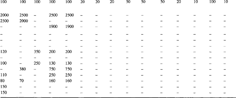
For frequencies in the range 0.5 to 10 MHz, the preference for NiZn or MnZn ferrite is dependent on many factors, including the power level to be handled and the permissible levels of harmonic distortion and intermodulation. These and other factors are covered in detail in various sources, including References 1 and 2, whilst Reference 3 contains a wealth of information, both theoretical and practical. Table 4.1 gives typical values for some of the more important parameters of typical MnZn and NiZn ferrites produced by one particular manufacturer, together with typical applications. The greater suitability of NiZn ferrites for higher frequencies is clearly illustrated. There are numerous manufacturers of ferrites and a selection of these (not claimed to be exhaustive) is given in Appendix 7.
Table 4.1a
Manganese-zinc ferrites for industrial and professional applications


(Reproduced by courtesy of MMG Mag Dev Limited
Table 4.1b
Nickel–zinc ferrites for industrial and professional applications

(Reproduced by courtesy MMG – Mag Dev Limited
The selection of a suitable low loss core material is an essential prerequisite to any successful wideband transformer design, but at least as much attention must be paid to the design of the windings. For wideband RF transformers, copper tape is often the best choice, at least for low impedance windings such as 50 Ω or less. This must be interleaved with insulating material, such as a strip of photographic mounting tissue (which, being waxed, sticks to itself when heated with the tip of an under-run soldering iron), or, for high power transformers a high dielectric strength electrical tape such as PTFE. For a high impedance winding, such as the secondary of a 50 Ω to 600 Ω balun (balanced to unbalanced transformer), wire is the best choice. It can be enamelled, or in the case of a high-power transformer, PTFE insulated. A single layer is always preferable, if at all possible, as stacked layers exhibit a much inferior Q factor - resulting in increased insertion loss - and an embarrassing amount of winding self-capacitance, leading to problems at the top end of the band especially in high power transformers. A single-layer secondary winding in a balun is inherently symmetrical of itself, but the balance can be easily upset by electrostatic coupling from the signal in the primary winding, the ‘hot’ end of which will be in phase with one end of the balanced secondary winding and in antiphase with the other. However, the use of an interwinding screen results in an undesirable increase in spacing between the primary and secondary, resulting in increased leakage inductance. Where a full width copper tape primary underneath a solenoidal wirewound secondary is used, the solution is to use the earthy end of the primary itself as the screen, by making the start of the primary the ‘hot’ end, carrying the earthy end on beyond the lead-out for an extra half turn for symmetry.
Baluns
Whether in the development or production phase, the degree of balance of a balun transformer needs to be checked to ensure all is well. Balance is measured in decibels and is defined as in Figure 4.2a, with a numerical example in Figure 4.2b: this is analysed into pure balanced and unbalanced components in Figure 4.2c. It can be seen that balance is defined independently of the transformer ratio. The balanced winding (usually regarded as the secondary) is shown in Figure 4.2 as having a centre tap connected to ground. Where neither the centre tap (if provided) nor any other part of the winding is connected to ground, the winding is said to be floating. In use, the balance achieved under these conditions is strongly influenced by the degree of balance of the load to which the transformer is connected. The balance of the transformer can conveniently be measured with the aid of a suitable balance pad. The purpose of such a pad is two-fold; firstly to terminate the secondary in its design impedance (e.g. 600 Ω), and secondly to provide a matched source, usually 50 Ω for the measuring system. The major cause of any difference between the two half secondary voltages, particularly at the lower end of the balun’s frequency range, is a difference in flux linkage with the primary. Because the difference is small compared with the total flux, the unbalanced component may be considered as arising from a negligibly small source impedance. The balance pad is used to pad this up to the characteristic impedance of the measurement system. Figure 4.3a shows the measurement set-up and Figure 4.3b shows balance pads for a number of common combinations of primary and secondary impedances. The insertion loss measured via the balun as in Figure 4.3a, less the allowance given in Figure 4.3b for the particular balance pad in use, gives the transformer balance ratio in decibels.


Figure 4.3 Special pads for measuring balance ratios X dB is the figure to be subtracted from the Insertion Loss of the transformer plus its Balance Ratio Pad to obtain the transformer balance
If the two ends of the primary winding on an ‘E’ core are brought out on the same side of the core, then the primary will consist of a whole number of turns around the centre limb, and similarly for the secondary, which is normal good practice. The core is dimensioned by the manufacturer to give equal flux density in the centre limb and each of the outer limbs when the windings consist of an integral number of turns. A half turn violates this condition, since the associated flux path is down one outer limb, returning through the centre and the other outer limb in parallel. In a high power transformer with only a few turns, the unequal flux density would reduce the power rating the transformer can handle if saturation in one of the limbs is to be avoided. Although we are concerned here only with transformers, it is worth pointing out that a half turn is even more undesirable in an inductor pot core, with its gapped centre limb. For every whole turn, the associated flux must pass through the centre limb with its air-gap, returning through the two or four outer limbs in parallel. With a half (or quarter or three-quarter) turn, the flux can pass down one or more outer limbs and back through other outer limbs, all ungapped. Thus a half turn may have substantially higher inductance than a whole turn, together with higher losses and a terrible temperature coefficient of inductance!
It was mentioned earlier that the useful LF (low frequency) response is set by the shunting effect of Lm across the transformed load resistance R’, resulting in a −3 dB point (see Figure 4.4a) at that frequency where the reactance of Lm has fallen to half the characteristic impedance of the primary circuit. This is clear from Figure 4.4b where the matched source is shown in the alternative ideal current generator form, with everything normalized to unity. The LF response can be maintained down to a slightly lower frequency by connecting a suitable capacitor in series with the primary winding, as in Figure 4.4c. This can reduce the loss from 3 dB without the capacitor, to 2.5 dB with it - not a spectacular improvement but may be enough to enable you to meet the specification requirement even though you cannot find a better core or squeeze another turn on. The problem is that the parallel combination of R’ and Lm is equivalent (at any frequency) to the series combination of a resistor R”, less than R’, and an inductance L’m, less than Lm. The capacitor can only improve things marginally by tuning out L’m; it cannot transform R” back to R’. R’ is of course equal to the characteristic impedance of the source and is thus the only value of load that can draw maximum power from the source.

One could however choose R’ to be deliberately mismatched to the source at mid band. The lower −3 dB point can then be extended down considerably by arranging that R” is equal to the source resistance. This results in a second order Chebychev high-pass response, the degree of LF extension possible being set by the acceptable pass-band ripple. In a small-signal transformer, where bandwidth may be more important than efficiency, this scheme may well be worthwhile. Note that when a capacitor is used in series with the primary, the impedance presented to the source way below the band of interest rises towards infinity rather than falling towards a short circuit. This characteristic can be useful in some applications.
A similar marginal improvement can be had at the HF end of the transformer’s range, where the response has fallen by 3 dB due to the increasing reactance of the leakage inductance. Here again capacitance can be used, this time in parallel with the transformer, to tune out the leakage inductance. Again, the 3 dB point can be improved to 2.5 dB, pushing up the −3 dB frequency by a small amount, or by rather more if a second order Chebychev low-pass response is acceptable. The capacitance can be connected either up- or downstream of the leakage inductance, i.e. across the primary or secondary winding. In the latter case, it may well be possible to build the capacitance into the transformer, by using wire with thin insulation for the secondary, or possibly by using a multilayer winding.
There is one case where tuning can be used to overcome the deleterious effect of leakage inductance completely, admittedly only at one frequency - although that is no problem in this particular application. The application in question is a crystal filter. These are available very cheaply in standard frequencies such as 10.7 MHz, 21.4 MHz, 45 MHz, etc., being usually implemented with monolithic dual resonators, or even in the latest designs, quad resonators. However, this technology is not appropriate to small quantities of filters of a non-standard frequency. Here, a filter is more likely to use discrete crystals, the classical configuration being the lattice filter, using four crystals per section. The arrangement of Figure 4.5a is more economical, using only two crystals per section, with the aid of a balun transformer. In this instance it is essential that the centre tap of the balanced secondary winding be effectively earthed and that the voltages applied to the two crystals are exactly equal in amplitude and in antiphase. This notwithstanding the wildly unequal impedances of the two crystals across the band, bearing in mind that for optimum band-pass response, the two crystals have different series resonant frequencies. In this application, the problem is not the leakage inductance between primary and secondary, but that between the two halves of the secondary. The equivalent circuit can be drawn as two perfectly coupled half windings, with the leakage inductance in series with the centre tap lead-out. If the load impedances connected to the ends of the secondary, although varying with frequency, were always identical at any given frequency, the leakage inductance would be immaterial since no current would flow through it. Unfortunately this is not the case, but by inserting capacitance at point X in Figure 4.5a and tuning it to series resonance with the leakage inductance at the centre of the filter’s pass band, the (inaccessible) junction of the perfectly coupled pair of windings is effectively shorted directly to earth. This short circuit is only effective at the resonant frequency of the leakage inductance and the inserted capacitance, but due to the L/C ratio of these being much lower than that of the crystals, it holds over the whole of the filter’s pass band. Incidentally, if a simpler second-order filter (single pole low-pass equivalent) will suffice, the even more economical arrangement of Figure 4.5b may be used. Here, with the capacitance C set equal to C0, the parallel capacitance of the crystal, a symmetrical response results. Tweaking C up or down in value will give a deep notch on one side of the response or the other, an arrangement popular at one time in amateur receivers, to notch out a strong CW signal when ‘DXing’, i.e. communicating with a very distant station.

For low power applications, a wide range of ready-made RF transformers is available from manufacturers such as Mini-Circuits, Toko, etc. These usually have one winding rated for 50 Ω use, with various ratios from 1:1 up to 16:1 being available, covering frequencies up to VHF or UHF, and covering a frequency range of between 30:1 and 1000:1. With low interwinding capacitances, these transformers, often in surface mounting packages, are widely used as baluns (with one or both windings being centretapped), and/or for impedance matching purposes. 75 Ω models are also available.
Line transformers
Finally, no discussion of RF transformers would be complete without covering line transformers. These were popularized by a paper published as long ago as 1959 [4], although the idea was not new even then, Ruthroff’s paper containing five references to earlier work. The basic principle of the transmission line transformer is to cope with the leakage inductance and winding capacitance by making them the distributed L and C of an RF line; a neat idea, although in the process dc isolation between primary and secondary is lost, in many cases. Figure 4.6a shows a 1:1 inverting transformer: the impedance of the line should equal the nominal primary and secondary impedance. If this is 50 Ω then miniature coax can conveniently be used. Wire 1-2, the inner, carries (in addition to the load current drawn by R, which returns through 4-3 and hence produces no net flux on the core) the magnetizing current needed to establish the flux on the core. This magnetizing current returns via the connection between the earthy end of the load and the earthy end of the source. The flux induces in series with both outer and inner a voltage equal to the voltage applied between points 1 and 3 (ground). The arrangement can be regarded as an ideal inverting transformer in series with a length of transmission line. The higher the permeability of the core, the fewer turns will be needed to obtain sufficient magnetizing inductance for operation down to the lowest frequency required, permitting a shorter length of transmission line to be used. In the case of the 1:1 inverting transformer, the length of the line is immaterial, except of course insofar as if the electrical length reaches λ/2 at the top end of the band, the output will be back in phase with the input. Ruthroff states that since both ends of the load R are isolated from ground by coil reactance, either end can be grounded, and that if the midpoint of the resistor is grounded then the output is balanced. In this case, however, the balance is not complete, as some magnetizing current is still needed (exactly half as much as in the inverting case), and this must now return through one-half of the load. Nevertheless, the winding arrangement of Figure 4.6a is frequently used as a balun and proves satisfactory where the frequency range is only an octave or so, since it is then easy to provide enough primary inductance to hold the residual unbalance to acceptable proportions. Further, when the arrangement is employed as a balun rather than as an inverting transformer, the phase relation between input and output is usually immaterial. In this case it may be possible to use a long enough length of line to render a ferrite core unnecessary - a typical example is the coaxial downlead from a TV antenna which acts as a balun for free. Where a very wideband balun is required, the degree of balance at the bottom end of the frequency range can be preserved by providing a return route for the magnetizing current, as in Figure 4.6b. (Note that a dot indicates the start end of winding, all windings being in the same sense.)

The isolation of one end of the line from the other provided by the end to end coil reactance means that the output can be stacked up on top of the input, to give twice the output voltage, as in Figure 4.6c. This provides a non-inverting 4:1 impedance ratio transformer. Ideally, the impedance of the line used should be the geometric mean of the input and output impedances, i.e. 100 Ω in the case of a 50 Ω to 200 Ω transformer: this is easily implemented with two lengths of self-fluxing enamelled magnet wire twisted together, by a suitable choice of gauge, insulation thickness (wire manufacturers offer a choice of fine, medium or thick) and a number of turns per inch twist [5]. Note that at the frequency where the electrical length of the winding is λ/4, the output voltage stacked up on top of the input will be in quadrature, so the output voltage will be only 3 dB higher than the input, not 6 dB, i.e. you no longer have a 4:1 impedance ratio transformer. So it pays to try and keep the electrical length of the winding at the highest required frequency to a tenth of a wavelength or less; in this case the characteristic impedance of the line used is not too critical.
Reference 4 discusses a number of other circuit arrangements and many others have since been described, mostly limited to certain fixed impedance ratios such as 4:1, 9:1, and 16.1, sometimes combined with an unbalanced to balanced transition or vice versa. Reference 6 is useful, while Reference 7 discusses slipping an extra turn or two onto the core, to obtain ratios intermediate between those mentioned above. Line transformers can usefully provide bandwidths of up to 10 000:1, given a suitable choice of core. However, where a much more modest bandwidth is adequate, it may be possible to omit the core entirely, e.g. the case of a TV downlead acting as a balun, as already mentioned. Freed from the constraints of a core, it is possible to consider using a non-constant impedance line. In particular, balanced transmission lines having a characteristic impedance increasing exponentially with distance were described in patents lodged in America, Germany and Australia in the 1920s. Reference 8 describes a quasi-exponentially tapered line transformer providing a 200 Ω to 600 Ω transition over the range 4 to 27.5 MHz. True, it is 41 m long, but then it does consist of nothing but wire (plus a few insulating supports) and has a rating of 20 kW continuous, 30 kW peak.
References
1. Snelling, E.C. Soft Ferrites, Properties and Applications, London, Butterworths, 1969.
2. John Wiley and Sons, USA Snelling, E.C., Giles, A.D. Ferrites for Inductors and Transformers, UK, Research Studies Press Ltd. UK, 1983.
3. DeMaw, M.F. Ferromagnetic-Core Design and Application Handbook, USA, Prentice Hall, 1981.
4. August Ruthroff, C.L. Some Broad-Band Transformers. Proceedings of the I.R.E., 1959:1337–1342.
5. December Lefferson, P. Twisted magnet wire transmission line. IEEE Transactions on Parts, Hybrids and Packaging, 1971;PHP-7(4):148–154.
6. Granberg, H. Broadband Transformers and Power Combining Techniques for RF. Motorola Application Note AN-749 1975.
7. 16 August Krauss, H.L., Allen, C.W. Designing toroidal transformers to optimize wideband performance. Electronics 1973.
8. February Young, S.G. H.F. exponential-line transformers. Electronic and Radio Engineer 1959;40–44.