Screening
The following information on screening is reproduced by courtesy of Laird Technologies Ltd, from their Materials Design Manual.
The need to control EMC
The result of failure to achieve EMC can range from mild annoyance through serious disruption of legitimate activities, to health and safety hazards. The security of information being processed by electronic means is a vital commercial and military interest, often referred to by the word TEMPEST. The electrical signals corresponding to the information may leak, by radiation or conduction, from the processing equipment and be intercepted by suitable sensitive receiving equipment.
Automotive electronics has extended, for example, into engine management and antiskid braking systems. There are evident safety implications if such electronic devices malfunction when the vehicle is subject to legitimate RF fields from on-board or nearby radio transmitters.
Finally, the explosion of nuclear devices results in an intense burst of radio energy in the HF band which, at distances beyond the likelihood of thermal blast damage, can cause temporary malfunction or permanent damage to electronic equipment. This is known as EMP, Electro-Magnetic Pulse.
Most countries recognise the need to control EMC and have civil EMC specifications which must be met internally and also by importers of electronic equipment. These specifications mainly control the level of emissions from the equipment but it will not be long before the susceptibility of civil equipment to externally produced electromagnetic energy will be controlled by specification. Military EMC specifications have long covered both emissions and susceptibility.
Sources of EMC problems and their containment
The operation of all electrical or electronic devices involves the changing of voltage or current levels intermittently or continuously, sometimes at fast rates. This results in the development of electro-magnetic energy at discrete frequencies and over bands of frequencies. In general, the circuit will radiate this energy into the space around it and also conduct the energy into the wiring, perhaps to emerge along the external power, signal or control lines.
Figure 2 shows the role of enclosure screening in limiting the coupling of unwanted radiation to a victim equipment. Figure 2 also shows how that victim equipment can be protected against external RF fields.

Figure 2
These notes do not go into any detail of the limitation of conducted interference by cable screening and filtering. The information is readily available from specialist manufacturers of line filters, screened cable and screened and filtered connectors. However, the attention is drawn, at the appropriate point, to the need for integrating all EMC measures to ensure the required results. For example, the necessary penetration of a screening enclosure by a screened cable or the output from an electrical filter, requires meticulous attention to achieving a low impedance electrical bond between enclosure and connector body or filter body.
E-M wave hits metallic barrier
Figure 3 shows, in general terms, what happens when an electro-magnetic wave strikes a metallic barrier.

Figure 3
The incoming wave has two components, an electric field and a magnetic field, at right-angles to each other and to the direction of travel. The relative strengths of the two fields will be detailed later. Consider just the electric field which has strength Ei when it hits the barrier. Some of the energy is reflected back, strength Er, but some carries on into the barrier, initially at strength Eit.
This transmitted component gets absorbed as it travels through the barrier and arrives at the second face at strength E2i. Once more the energy divides into a reflected component E2r and a transmitted component EO. The‘E’ field screening effectiveness is defined as 20 log10Ei/Eodb.
The use of the decibel is convenient to cope with the wide range of values encountered. A very modest screen might reduce the emergent field to one-tenth of the incident value, i.e. a screening effectiveness of 20 dB. On the other hand a demanding application might require a reduction to one hundred thousandth of the incident field - a screening effectiveness of 100 dB.
The incident‘H’ field also suffers reflection and absorption as it passes through the front and back faces of the barrier, just like the‘E’ field. However, the relative amounts are usually different as will be seen.
It is convenient to define screening effectiveness as the sum of three terms, each expressed in dB, and have a closer look at the actual values of these terms.

Figure 4
Absorption loss
Figure 5 shows the absorption loss depends on the thickness of the barrier, the frequency of interest and two properties of the barrier material that is, the conductivity and the permeability, relative to copper. The table shows values for typical materials of interest.

Figure 5
Figure 6 shows the variation of absorption loss with frequency for two typical screening materials, copper and steel. Two thicknesses are considered 5 mm (0.200″) and 0.5 mm (0.020″).

Figure 6
Reflection loss (plane wave)
The reflection loss increases with the ratio of the impedance of the incident wave to the impedance of the screen material. For plane EM waves, such as exist beyond a distance of about one-sixth of a wavelength from the source, the wave impedance is constant at about 377 ohms. The impedance of the screen material is proportional to the square root of the frequency times the permeability divided by the conductivity. Good conductors and nonmagnetic materials give low screen impedance and hence high reflection loss. Working at higher frequencies raises the screen impedance and lowers the reflection loss. Figure 7 shows some typical values for reflection loss.
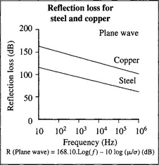
Figure 7
Combined absorption and reflection loss for plane waves
Figure 8 shows the total shielding effectiveness for a copper screen 0.5 mm (0.02”) thick, in the far field, where the wave front is plane and the wave impedance is constant at 377 ohms. The poor absorption at low frequencies is compensated by the high reflection loss. The multiple reflection correction factor, B, is normally neglected for electric fields because the reflection loss is so large. This point will be considered later.

Figure 8
Reflection loss in the near field
The wave impedance in the near field depends on the nature of the source of the wave and the distance from that source. Figure 9 shows that for a rod or straight wire antenna, the wave impedance is high near the source. The impedance falls with distance from the source and levels out at the plane wave impedance value of 377 ohms. In contrast, if the source is a small wire loop, the field is predominantly magnetic and the wave impedance is low near the source. The impedance rises with distance away from the source but will also level at the free space value at distance beyond about one-sixth wavelength.

Figure 9
As detailed in the‘Enclosure Design’ section, EMI shields are required in a range of materials for reasons other than those of attenuation alone. Such factors as compatibility with existing materials, physical strength and corrosion resistance, are all relevant. The properties of those materials used by RFI Shielding Ltd., are discussed here to assist in selection of the most suitable with regard to these factors. Comparative tables are provided at the end of the section.
Remembering that reflection loss varies as the ratio of wave to screen impedance it can be seen that reflection loss will depend on the type of wave being dealt with and how far the screen is from the source. For small, screened, equipments we are usually working in the near field and have to deal with this more complex situation. Figure 10 shows the relevant formulae.
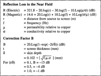
Figure 10
The procedure for calculating the correction factor, B, is also shown in Figure 10. This is normally only calculated for the near-field magnetic case and then only if the absorption loss is less than 10 dB. Re-reflection within the barrier, in the absence of much absorption, results in more energy passing through the second face of the barrier. Thus the correction factor is negative indicating a reduced screening effectiveness.
Figure 11 illustrates the variation of reflection loss with distance and frequency in the near field for a copper screen. Notice that in the near-field, as reflection loss for electric fields is higher, the closer the screen is to the source, the better. For magnetic fields the reverse is true.
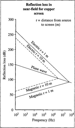
Figure 11
The electronic design engineer can therefore specify his screening requirements in terms of the emission frequency range of interference sources, their location relative to the screening and the screening effectiveness to be achieved.
The mechanical design engineer can then begin to explore screening enclosure material options and calculate their screening effectiveness.
Screen materials
The provision of high screening effectiveness at very low frequencies can only be achieved by high permeability materials. The permeability of these materials falls off with frequency and can also be reduced if the incident magnetic field is high. Further, the permeability may be reduced by the mechanical working of the metal necessary to fabricate the required shape of screen. For all these reasons the exploitation of high permeability materials for screening purposes is a demanding task and recourse should be made to a specialist supplier in this field.
On the other hand, at higher frequencies it becomes possible to use cheaper metallic materials at quite modest thickness. Some typical screen materials are listed in Figure 12. Depending on the screening effectiveness requirement, which must never be overstated, it often becomes cost-effective to distinguish between a material for electric screening purposes and another material which provides the physical support and determines the mechanical integrity of the screened enclosure.

Figure 12
As an example, consider a plastic box which provides mechanical and, perhaps, environmental protection to an enclosed electronic circuit. This box might be lined with flexible laminates, electroless plating, conductive paints, metallic foil tapes, wire spray or vacuum metallizing. The box might be made of conductive plastic.
Large screened enclosures are often made of steel-faced wooden sheets or of welded steel sheets mounted on a structural framework.
The final choice will depend on considerations involving the ability to make effective joints to the screening material for items such as access panels, connectors and windows; the avoidance of significant galvanic corrosion; the ability to withstand whatever external environment is stipulated, including mechanical shock and vibration. All these factors must be considered against the cost of achieving the stated required performance.
Integrity of a screened enclosure
It has been shown that good screening effectiveness can generally be achieved by reasonably thin metal screens but it is assumed that the screen is continuous and fully surrounds the sensitive item, without gaps or apertures. In practice it is rarely possible to construct a screen in this way. The screen may have to be fabricated in pieces which must be joined together. It may be necessary to penetrate the screen to mount components.
Any decrease in the effective conductivity of the screen, because of joints, will reduce screening effectiveness. Any slots or apertures can act as antennas allowing RF energy to leak in or out. Figure 13 lists some of the reasons why screened enclosures may require joints or apertures.
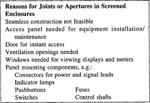
Figure 13
Now consider, briefly, the attenuation of EM waves through a metallic gap or hole.
Gaps and holes in screens
Concerning the gap or hole which penetrates the screen, as a waveguide through which EM energy is flowing. If the wavelength of this energy is too long compared with the lateral dimensions of the waveguide, little energy will pass through. The waveguide is said to be operating beyond cut-off.
Figure 14 shows formulae for cut-off frequency in round and rectangular waveguide. For operating frequencies much less than the cut-off frequency the formulae for shielding effectiveness are also given. Notice that the attenuation well below cut-off depends only on the ratio of length to diameter. Attenuation of about 100 dB can be obtained for a length to diameter ratio of 3. Thus it may be possible to exploit the waveguide properties of small holes in thick screens where penetration is essential. An alternative way of achieving a good length/diameter ratio is to bond a small metallic tube of appropriate dimensions, normal to the screen.

Figure 14
This theory and its extension to multiple holes, forms the design basis for commercially available perforated components such as viewing and ventilation panels which must have good screening effectiveness.
Seams and joints
For joints between sheets which are not required to be parted subsequently, welding, brazing or soldering are the prime choices. The metal faces to be joined must be clean to promote complete filling of the joint with conductive metal.
Screws or rivets are less satisfactory in this application because permanent low impedance contact along the joint between the fastenings is difficult to ensure.
For joints which cannot be permanently made, conducting gaskets must be used to take up the irregularities in the mating surfaces. Consideration should be given to the frequency and circumstances in which such joints will be opened and closed during the life of the equipment. One classification defines Class A, B and C joints. Class A is only opened for maintenance and repair. In a Class B joint the relative positions of mating surfaces and gasket are always the same, e.g. hinged lids and doors. In a Class C joint the relative positions of mating surfaces and gasket may change, e.g. a symmetrical cover plate.
A wide range of gasket materials is available commercially. They include finger strip; wire mesh with or without elastomer core; expanded metal and oriented wire in elastomer and conductive elastomers. Most suppliers provide estimates of screening effectiveness which can be achieved with the various gaskets. The gaskets come in a variety of shapes to suit many applications. The selection of a suitable gasket depends on many factors, the most important of which are listed in Figure 15.

Figure 15